CN115194464A - Automatic assembling equipment for robot joint - Google Patents
Automatic assembling equipment for robot joint Download PDFInfo
- Publication number
- CN115194464A CN115194464A CN202210711884.6A CN202210711884A CN115194464A CN 115194464 A CN115194464 A CN 115194464A CN 202210711884 A CN202210711884 A CN 202210711884A CN 115194464 A CN115194464 A CN 115194464A
- Authority
- CN
- China
- Prior art keywords
- assembly
- joint
- conveyor line
- manipulator
- automatic assembling
- Prior art date
- Legal status (The legal status is an assumption and is not a legal conclusion. Google has not performed a legal analysis and makes no representation as to the accuracy of the status listed.)
- Pending
Links
- 230000007246 mechanism Effects 0.000 claims abstract description 21
- 230000000007 visual effect Effects 0.000 claims description 10
- 238000005034 decoration Methods 0.000 claims description 4
- 239000003292 glue Substances 0.000 claims description 4
- 239000011257 shell material Substances 0.000 description 57
- 239000000463 material Substances 0.000 description 9
- 238000010586 diagram Methods 0.000 description 7
- 238000007789 sealing Methods 0.000 description 4
- 238000004026 adhesive bonding Methods 0.000 description 3
- 230000009471 action Effects 0.000 description 2
- 238000010073 coating (rubber) Methods 0.000 description 2
- 230000000875 corresponding effect Effects 0.000 description 2
- 238000003860 storage Methods 0.000 description 2
- 230000008094 contradictory effect Effects 0.000 description 1
- 230000002349 favourable effect Effects 0.000 description 1
- 238000004519 manufacturing process Methods 0.000 description 1
- 238000000034 method Methods 0.000 description 1
- 238000004806 packaging method and process Methods 0.000 description 1
- 239000003973 paint Substances 0.000 description 1
- 230000008569 process Effects 0.000 description 1
- 238000004904 shortening Methods 0.000 description 1
- 230000001360 synchronised effect Effects 0.000 description 1
Images
Classifications
-
- B—PERFORMING OPERATIONS; TRANSPORTING
- B23—MACHINE TOOLS; METAL-WORKING NOT OTHERWISE PROVIDED FOR
- B23P—METAL-WORKING NOT OTHERWISE PROVIDED FOR; COMBINED OPERATIONS; UNIVERSAL MACHINE TOOLS
- B23P21/00—Machines for assembling a multiplicity of different parts to compose units, with or without preceding or subsequent working of such parts, e.g. with programme control
- B23P21/004—Machines for assembling a multiplicity of different parts to compose units, with or without preceding or subsequent working of such parts, e.g. with programme control the units passing two or more work-stations whilst being composed
-
- B—PERFORMING OPERATIONS; TRANSPORTING
- B25—HAND TOOLS; PORTABLE POWER-DRIVEN TOOLS; MANIPULATORS
- B25J—MANIPULATORS; CHAMBERS PROVIDED WITH MANIPULATION DEVICES
- B25J9/00—Programme-controlled manipulators
- B25J9/16—Programme controls
- B25J9/1612—Programme controls characterised by the hand, wrist, grip control
-
- B—PERFORMING OPERATIONS; TRANSPORTING
- B25—HAND TOOLS; PORTABLE POWER-DRIVEN TOOLS; MANIPULATORS
- B25J—MANIPULATORS; CHAMBERS PROVIDED WITH MANIPULATION DEVICES
- B25J9/00—Programme-controlled manipulators
- B25J9/16—Programme controls
- B25J9/1679—Programme controls characterised by the tasks executed
- B25J9/1687—Assembly, peg and hole, palletising, straight line, weaving pattern movement
-
- B—PERFORMING OPERATIONS; TRANSPORTING
- B25—HAND TOOLS; PORTABLE POWER-DRIVEN TOOLS; MANIPULATORS
- B25J—MANIPULATORS; CHAMBERS PROVIDED WITH MANIPULATION DEVICES
- B25J9/00—Programme-controlled manipulators
- B25J9/16—Programme controls
- B25J9/1694—Programme controls characterised by use of sensors other than normal servo-feedback from position, speed or acceleration sensors, perception control, multi-sensor controlled systems, sensor fusion
- B25J9/1697—Vision controlled systems
Landscapes
- Engineering & Computer Science (AREA)
- Mechanical Engineering (AREA)
- Robotics (AREA)
- Health & Medical Sciences (AREA)
- General Health & Medical Sciences (AREA)
- Orthopedic Medicine & Surgery (AREA)
- Automatic Assembly (AREA)
Abstract
The invention discloses automatic assembling equipment for a robot joint, which comprises a conveying line assembly, a plurality of automatic assembling mechanisms and a joint shell feeding device positioned at one end of the conveying line assembly; the joint shell feeding device comprises a bearing platform and a first manipulator; the bearing platform is used for placing a joint shell; the first manipulator is used for grabbing and transferring the joint shell to the conveying line assembly; the automatic assembling mechanisms are sequentially arranged along the conveying direction of the conveying line assembly. According to the technical scheme provided by the invention, the joint shell to be assembled is placed on the bearing platform, and is grabbed and transferred to the conveying line assembly through the first mechanical arm during assembly, and then the joint shell is sequentially conveyed to each automatic assembly mechanism through the conveying line assembly, so that the joint shell is automatically fed, and the joint assembly efficiency is improved.
Description
Technical Field
The invention relates to the field of robots, in particular to automatic assembling equipment for a robot joint.
Background
The robot is an automatic operation device which can imitate some action functions of a human arm and is used for grabbing and carrying objects or operating tools according to a fixed program; it is widely applied to the automated production industry. The robot comprises a plurality of joints and joint arms, two adjacent joints are connected through the joint arms, and corresponding action functions are completed through mutual matching of the joints and the joint arms.
When the robot is produced, all joints of the robot are assembled firstly, then all the joints are assembled together through the joint arms, and finally a finished robot product is obtained. However, at present, the robot is manually assembled, and the assembly efficiency is low.
Disclosure of Invention
The invention mainly aims to provide automatic assembling equipment for a robot joint, and aims to solve the technical problem that the existing robot joint is low in assembling efficiency.
In order to achieve the purpose, the invention provides automatic assembling equipment for a robot joint, which comprises a conveying line assembly, a plurality of automatic assembling mechanisms and a joint shell feeding device positioned at one end of the conveying line assembly, wherein the joint shell feeding device comprises a bearing platform and a first manipulator, and the bearing platform is used for placing a joint shell; the first manipulator is used for grabbing and transferring the joint shell to the conveying line assembly; the automatic assembling mechanisms are sequentially arranged along the conveying direction of the conveying line assembly.
In some embodiments, the conveying line assembly is a circulating conveying line, a positioning fixture for placing a joint housing is fixedly arranged on the conveying line assembly, and the first manipulator transfers the joint housing on the bearing platform to the positioning fixture.
In some embodiments, the circulating conveying lines comprise an upper conveying line and a lower conveying line which are opposite in conveying direction, the upper conveying line is used for conveying the positioning jig placed with the joint shell, and the lower conveying line is used for conveying the empty positioning jig.
In some embodiments, the circulating conveyor line further comprises at least two second manipulators, wherein one second manipulator is positioned at one end of the upper conveyor line and is arranged close to the first manipulator for placing a positioning fixture on the upper conveyor line, and the first manipulator is used for placing a joint housing on the positioning fixture;
and the other second manipulator is positioned at the other end of the upper-layer conveying line and used for transferring the empty positioning jig on the upper-layer conveying line to the lower-layer conveying line for backflow.
In some embodiments, the number of the carrying platforms is two, and the first manipulator is located between the two carrying platforms.
In some embodiments, a driving device is disposed below the carrying platform, and the driving device is used for driving the carrying platform to move in the direction close to the conveying line assembly.
In some embodiments, the first robot comprises a first robot arm and a first jaw assembly disposed at a distal end of the first robot arm;
and/or the second manipulator comprises a second mechanical arm and a second clamping jaw assembly arranged at the tail end of the second mechanical arm.
In some embodiments, the automated assembly equipment for robotic joints further comprises a first visual positioning component disposed at the end of the first robotic arm and/or a second visual positioning component disposed at the end of the second robotic arm.
In some embodiments, the automatic assembling equipment for the robot joint further comprises a plurality of stopping devices for stopping and positioning the joint shell conveyed on the conveying line assembly.
In some embodiments, the stopping device is located below the conveying line assembly, and the stopping device includes a driving member, a connecting seat, and a stopping member, the connecting seat is connected with the driving member, the stopping member is rotatably disposed on the connecting seat, and an output executing end of the driving member is connected with the stopping member for driving the stopping member to rotate.
In some embodiments, the number of automated assembly mechanisms includes at least one of an internally threaded glue assembly, a seal ring assembly, and a trim ring assembly.
According to the technical scheme provided by the invention, the joint shell to be assembled is placed on the bearing platform, and is grabbed and transferred to the conveying line assembly through the first manipulator during assembly, and then the joint shell is sequentially conveyed to each automatic assembling mechanism through the conveying line assembly, so that the joint shell is automatically fed, and the joint assembling efficiency is improved.
Drawings
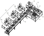
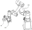
Fig. 1 is a schematic structural diagram of an automatic assembling apparatus for a robot joint according to an embodiment of the present invention;
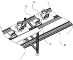
FIG. 2 is a schematic view of a portion of the conveyor line assembly of FIG. 1;
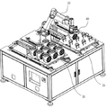
FIG. 3 is a schematic structural view of a joint casing feeding device in FIG. 1;
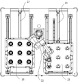
FIG. 4 is a front perspective view of the joint housing feeder of FIG. 3;
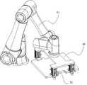
fig. 5 is a schematic structural diagram of the first robot in fig. 3;
FIG. 6 is a schematic diagram of the second robot of FIG. 1;
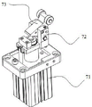
fig. 7 is a schematic structural view of the stopper device of fig. 2.
The implementation, functional features and advantages of the present invention will be further described with reference to the accompanying drawings.
Detailed Description
In the following, the embodiments of the present invention will be described in detail with reference to the drawings in the following, and it is apparent that the described embodiments are only a part of the embodiments of the present invention, and not all embodiments. All other embodiments, which can be derived by a person skilled in the art from the embodiments given herein without making any creative effort, shall fall within the protection scope of the present invention.
It should be noted that all directional indicators (such as up, down, left, right, front, back \8230;) in the embodiments of the present invention are only used to explain the relative positional relationship between the components, the motion situation, etc. in a specific posture (as shown in the attached drawings), and if the specific posture is changed, the directional indicator is changed accordingly.
It will also be understood that when an element is referred to as being "secured to" or "disposed on" another element, it can be directly on the other element or intervening elements may also be present. When an element is referred to as being "connected" to another element, it can be directly connected to the other element or intervening elements may also be present.
In addition, the descriptions related to "first", "second", etc. in the present invention are for descriptive purposes only and are not to be construed as indicating or implying relative importance or implicitly indicating the number of technical features indicated. Thus, a feature defined as "first" or "second" may explicitly or implicitly include at least one such feature. In addition, technical solutions between various embodiments may be combined with each other, but must be realized by a person skilled in the art, and when the technical solutions are contradictory or cannot be realized, such a combination should not be considered to exist, and is not within the protection scope of the present invention.
Referring to fig. 1, 3 and 4, fig. 1 is a schematic structural diagram of an automatic assembling apparatus for a robot joint according to an embodiment of the present invention, fig. 3 is a schematic structural diagram of a joint housing feeding device in fig. 1, and fig. 4 is a front projection view of the joint housing feeding device in fig. 3.
The invention provides automatic assembling equipment for a robot joint, which comprises a conveyor line assembly 10, a plurality of automatic assembling mechanisms 30 and a joint shell feeding device 20 positioned at one end of the conveyor line assembly 10, wherein the joint shell feeding device 20 comprises a bearing platform 21 and a first manipulator 22, and the bearing platform 21 is used for placing a joint shell; the first manipulator 22 is used for grabbing and transferring the joint shell to the conveying line assembly 10; a plurality of automatic assembling mechanisms 30 are sequentially arranged along the conveying direction of the conveyor line assembly 10.
In this embodiment, the conveyor line assembly 10 is used for conveying the joint housings to be assembled to the respective automatic assembling mechanisms 30, and one end of the conveyor line assembly 10 is provided with a joint housing feeding device 20, and the joint housing feeding device 20 is used for supplying the joint housings to be assembled to the conveyor line assembly 10. Joint shell loading attachment 20 includes load-bearing platform 21 and first manipulator 22, and load-bearing platform 21 is used for placing the joint shell, and first manipulator 22 is used for shifting the joint shell on the load-bearing platform 21 to transfer line subassembly 10 on, realizes comparing in present artifical material loading mode to the automatic material loading of joint shell, is favorable to improving articular packaging efficiency.
The conveying line assembly 10 can adopt a synchronous belt to convey the joint housing and also can adopt a roller to convey the joint housing, including but not limited to, and the person skilled in the art can design according to the actual situation. The first manipulator 22 may adopt a structural form of a multi-axis linear module + a material taking assembly (a suction nozzle or a clamping jaw, etc.), or may also adopt a structural form of a mechanical arm + a material taking assembly (a suction nozzle or a clamping jaw, etc.), including but not limited to this, and those skilled in the art can design the manipulator according to actual situations.
In some embodiments, automatic assembling devices are correspondingly disposed at the automatic assembling mechanisms 30, and the joint housings are sequentially assembled by the automatic assembling devices, so as to further improve the assembling efficiency of the joints.
In some embodiments, the conveyor line assembly 10 provided by the present invention is a circulating conveyor line, a positioning fixture 40 for placing a joint housing is fixedly disposed on the conveyor line assembly 10, and the first robot 22 transfers the joint housing on the carrying platform 21 to the positioning fixture 40.
In the present embodiment, the conveyor line assembly 10 is a circulating conveyor line, such as an O-ring, including but not limited to, and can be designed by those skilled in the art according to the actual situation. The fixed positioning jig 40 that is used for bearing the weight of the joint shell that is provided with on the transfer chain subassembly 10, during joint shell material loading, transfer the joint shell to positioning jig 40 through first manipulator 22 on, then carry the positioning jig 40 that bears the weight of the joint shell to each automatic assembly mechanism 30 department in proper order through transfer chain subassembly 10 and assemble, after the equipment is accomplished, take off the joint shell from positioning jig 40, then the material level department of going up of joint shell is carried to empty positioning jig 40 to rethread transfer chain subassembly 10, so the circulation is reciprocal. The positioning fixture 40 is mainly used for bearing and fixing the joint shell, and the joint shell is placed on the conveying line assembly through the positioning fixture so as to ensure the position accuracy of the joint shell.
Referring to fig. 2, fig. 2 is a schematic view of a portion of the conveyor line assembly 10 of fig. 1.
In some embodiments, the circulating conveyor line provided by the invention comprises an upper layer conveyor line 11 and a lower layer conveyor line 12 which are opposite in conveying direction, wherein the upper layer conveyor line 11 is used for conveying the positioning jig 40 with the joint shell placed thereon, and the lower layer conveyor line 12 is used for conveying the empty positioning jig 40.
In this embodiment, the conveyor line assembly 10 includes an upper conveyor line 11 and a lower conveyor line 12, and the upper conveyor line 11 and the lower conveyor line 12 are conveyed in opposite directions. When the joint shell is assembled, the positioning jig 40 is placed on the upper conveying line 11, then the joint shell to be assembled is placed on the positioning jig 40 of the upper conveying line 11, then the positioning jig 40 with the joint shell placed is conveyed to each automatic assembling mechanism 30 through the upper conveying line 11, after the assembly is completed, the assembled joint shell is taken down from the positioning jig 40, finally, the empty positioning jig 40 on the upper conveying line 11 is transferred to the lower conveying line 12, so that the empty positioning jig 40 flows back to the joint shell feeding end through the lower conveying line 12, and the circulation is repeated. Optionally, the automatic assembling apparatus provided in this embodiment further includes a third robot (not shown) disposed at one end of the conveyor line assembly 10, and configured to transfer the assembled joint housing on the upper conveyor line 11 to a predetermined area, and simultaneously transfer the empty positioning jig 40 on the upper conveyor line 11 to the lower conveyor line 12 for reflow. Further, the number of the third manipulators may be one or two, and those skilled in the art can design the manipulators according to actual situations.
In some embodiments, referring to fig. 1 and fig. 2, the robot joint automatic assembly apparatus further includes at least two second manipulators 50, wherein one second manipulator 50 is located at one end of the conveyor line assembly 10 and is disposed adjacent to the first manipulator 22 for placing the positioning fixture 40 on the upper layer conveyor line 11, and the first manipulator 22 is used for placing the joint housing on the positioning fixture 40; the other second robot 50 is located at the other end of the conveyor line, and is used for transferring the empty positioning jig 40 on the upper layer conveyor line 11 to the lower layer conveyor line 12 for reflow.
In this embodiment, at least one second manipulator 50 is respectively disposed at two ends of the conveyor line assembly 10, wherein one second manipulator 50 is located at one end close to the first manipulator 22, and is used for placing the positioning fixture 40 on the upper-layer conveyor line 11, and then the first manipulator 22 picks up the joint housing to be assembled from the bearing platform 21 and places the joint housing on the positioning fixture 40 of the upper-layer conveyor line 11. After the joint housing on the jig 40 to be positioned is assembled and taken down, another second robot 50 at the other end of the conveyor line module 10 transfers the empty positioning jig 40 from the upper conveyor line 11 to the lower conveyor line 12, so that the empty positioning jig 40 is returned to the joint housing feeding end through the lower conveyor line 12.
Alternatively, the first robot 22 in the above embodiment may replace one of the second robots 50 to complete the action of placing the positioning jig 40 on the upper layer conveying line 11, so that only one second robot 50 is needed, thereby reducing the equipment cost. The first robot 22 can be used to place the joint housing on the positioning jig 40 instead of the second robot 50 to perform the above-described operation.
In some embodiments, referring to fig. 3 and 4, the number of the carrying platforms 21 provided by the present invention is two, and the first robot 22 is located between the two carrying platforms 21.
In this embodiment, through the two bearing platforms 21, the joint shell can be loaded without stopping, so as to further improve the joint assembling efficiency. Before the joint shell is fed, the joint shell to be assembled is placed on the two bearing platforms 21, and after at least one of the two bearing platforms 21 is placed with the joint shell, the joint shell is fed.
When one of the two bearing platforms 21 is provided with a joint shell and the other bearing platform 21 is not provided with a joint shell, the robot can first grab the bearing platform 21 provided with the joint shell by the first manipulator 22, and meanwhile, the other bearing platform 21 not provided with the joint shell is supplied with materials. After all the joint shells on one of the bearing platforms 21 are transferred to the conveyor line assembly 10, the first manipulator 22 grabs the joint shells from the other bearing platform 21, meanwhile, supplies materials to the bearing platform 21 on which the joint shells are grabbed, and the operation is repeated in a circulating manner, so that the joint shells are fed without stopping, and the joint assembly efficiency is improved.
When the joint shells are placed on the two bearing platforms 21, the first manipulator 22 finishes taking the joint shell of one bearing platform 21, then picks the joint shell from the other bearing platform 21, and when the first manipulator 22 picks the joint shell from the other bearing platform 21, the bearing platform 21 which has picked the joint shell is supplied with materials, so that the processes are circulated, the continuous feeding of the joint shell is realized, and the joint assembly efficiency is improved.
In some embodiments, referring to fig. 4, a driving device 23 is disposed below the carrying platform 21, and the driving device 23 is used for driving the carrying platform 21 to move in a direction close to the conveyor line assembly 10.
In this embodiment, in order to further improve the joint assembling efficiency, after the joint housing is placed on the bearing platform 21, the driving device 23 drives the bearing platform 21 to move toward the direction close to the conveyor line assembly 10, so that the joint housing is located at the position close to the conveyor line assembly 10, thereby shortening the time for transferring the joint housing by the first manipulator 22, and achieving the purpose of improving the joint assembling efficiency.
In some embodiments, the driving device 23 of the present embodiment is used to drive the two carrying platforms to move toward or away from each other, specifically, when one of the carrying platforms 21 moves toward the direction close to the conveyor line assembly 10, the other carrying platform 21 moves away from the conveyor line assembly 10.
Wherein, drive arrangement 23 can drive two load-bearing platform 21 simultaneously and move in opposite directions or dorsad, for example can adopt the structure realization of motor + positive and negative lead screw, positive and negative lead screw has two opposite screw thread sections of screw direction, all installs the nut on every screw thread section, correspond a load-bearing platform 21 on two nuts respectively, when motor drive lead screw rotated, two nuts were in opposite directions or dorsad linear motion in two screw thread sections, then can drive two load-bearing platform 21 and move in opposite directions or dorsad. When the joint housings on one of the bearing platforms 21 are completely assembled, that is, one bearing platform 21 does not have a joint housing, and the joint housing needs to be placed on another station, and the related joint housing on the other bearing platform 21 needs to be close to the conveyor line assembly 10 to load the joint housing, at this time, the driving device 23 works, that is, the motor drives the positive and negative screw rods to rotate, so that the bearing platform 21 without the joint housing moves in the direction away from the conveyor line assembly 10, and the bearing platform with the related joint housing moves in the direction close to the conveyor line assembly 10; the driving device 23 can drive the two bearing platforms 21 to move simultaneously at one time, so that the bearing platform 21 without the joint shell can move outwards conveniently, and a worker can place the joint shell on the bearing platform 21 conveniently; while also facilitating movement of the carrier platform 21 of the articulated housing in a direction approaching the conveyor line assembly 10 to enable the first robot 22 to quickly grasp the articulated housing onto the conveyor line assembly 10.
In some embodiments, the driving device 23 includes an air cylinder, two linear guide rails disposed at intervals, and a slider slidably engaged with the two linear guide rails, the slider is mounted at the bottom of the supporting platform 21, a piston rod of the air cylinder is connected with the supporting platform 21 to drive the supporting platform 21 to move along the two linear guide rails, and the two linear guide rails are disposed along the direction perpendicular to the conveyor line assembly 10. Wherein, the cylinder can adopt motor and lead screw to replace, and the technical personnel in the art can design according to actual conditions.
Referring to fig. 5 and 6, fig. 5 is a schematic structural diagram of the first manipulator 22 in fig. 3, and fig. 6 is a schematic structural diagram of the second manipulator 50 in fig. 1.
In some embodiments, the first robot 22 of the present invention includes a first robot arm 221 and a first clamping jaw assembly 222 disposed at a distal end of the first robot arm 221; and/or the second robot arm 50 comprises a second robot arm 51 and a second gripper assembly 52 provided at the end of the second robot arm 51.
In this embodiment, the first robot arm 221 and the second robot arm 51 each have multiple degrees of freedom, such as four-axis, five-axis, or six-axis, which can be designed by those skilled in the art according to the actual situation. The end of the first robot arm 221 is provided with a first clamping jaw assembly 222, the first robot arm 221 is used for driving the first robot arm to move towards or away from the joint housing, and after the first clamping jaw assembly 222 moves to a preset position, the first clamping jaw assembly 222 is driven in a pneumatic or electric mode to clamp or release the joint housing.
The end of the second mechanical arm 51 is provided with a second clamping jaw assembly 52, the second mechanical arm 51 is used for driving the second mechanical arm to move towards or away from the joint shell, and after the second clamping jaw assembly 52 moves to the preset position, the second clamping jaw assembly 52 is driven in a pneumatic or electric mode to clamp or release the joint shell.
In some embodiments, referring to fig. 5, the automatic assembling apparatus for a robot joint further includes a first visual positioning assembly 60 and/or a second visual positioning assembly (not shown), wherein the first visual positioning assembly 60 is disposed at the end of the first robot arm 221, and the second visual positioning assembly is disposed at the end of the second robot arm 51.
In this embodiment, during joint shell material loading, first through first horn drive first clamping jaw subassembly 222 and first vision positioning subassembly 60 and remove to the top of load-bearing platform 21, then acquire joint shell's the position information of grabbing through first vision positioning subassembly 60, then snatch joint shell by first clamping jaw subassembly 222 according to this position information, avoid first clamping jaw subassembly 222 to appear grabbing partially or grab askew condition when snatching joint shell.
When the positioning jig 40 is loaded, the second mechanical arm 51 drives the second clamping jaw assembly 52 and the second visual positioning assembly to move to the upper side of the positioning jig 40, the grabbing position information of the positioning jig 40 is obtained through the second visual positioning assembly, then the second clamping jaw assembly 52 grabs the positioning jig 40 according to the position information, and the situation that the second clamping jaw assembly 52 grabs partially or askew when grabbing the positioning jig 40 is avoided.
In some embodiments, referring to fig. 2, the automatic assembling equipment for robot joints of the present invention further includes a plurality of stopping devices 70 for stopping and positioning the joint housings transported on the conveyor line assembly 10.
In this embodiment, when the joint housing is conveyed, the conveyor line assembly 10 performs stop positioning on the joint housing by the stop device 70, so that the joint housing stops at a preset station, and accordingly the joint housing is assembled at the station, for example, O-ring assembly, internal thread gluing, decoration ring assembly, and the like. The stopping devices 70 may be disposed on both sides of the conveyor line assembly 10, below the conveyor line assembly 10, or on both sides and below the conveyor line assembly 10, and may be designed by those skilled in the art according to the actual situation.
Referring to fig. 2 and 7, fig. 7 is a schematic structural view of the stop device 70 in fig. 2.
In some embodiments, the stopping device 70 provided by the present invention is located below the conveyor line assembly 10, the stopping device 70 includes a driving member 71, a connecting seat 72 and a stopping member 73, the connecting seat 72 is fixedly connected with the driving member 71, the stopping member 73 is rotatably disposed on the connecting seat 72, and an output execution end of the driving member 71 is connected with the stopping member 73 for driving the stopping member 73 to rotate.
In this embodiment, the stopping device 70 is disposed below the conveyor line assembly 10 and includes a driving member 71, a connecting seat 72 and a stopping member 73, the driving member 71 is connected to the conveyor line assembly 10 through a mounting plate, the connecting seat 72 is mounted on the driving member 71, and the stopping member 73 is rotatably disposed on the connecting seat 72. When the joint shell is conveyed to a certain automatic assembly mechanism 30, the driving piece 71 drives the stop piece 73 to rotate, so that the stop piece 73 rotates to a position for stopping the joint shell; when the joint housing is assembled at this automatic assembling mechanism 30, the driving member 71 drives the stopper 73 to rotate in the reverse direction, so that the stopper 73 rotates to a lower position of the joint housing.
In some embodiments, the driving member 71 is a cylinder, the cylinder is disposed in a vertical direction, the stopper 73 is disposed in a substantially V-shape, and a piston rod of the cylinder is vertically upward and connected to one side of the stopper 73. When the piston rod of the cylinder moves up and down, the stop member 73 connected with the piston rod of the cylinder is driven to move, and the stop member 73 is rotationally connected with the connecting seat 72, so that the stop member 73 is driven to rotate by the piston rod of the cylinder.
In some embodiments, a pulley is disposed on one side of the stop member 73 abutting against the joint housing, and the stop member 73 abuts against the joint housing or the positioning jig 40 through the pulley to reduce friction between the stop member 73 and the joint housing or the positioning jig 40, so as to reduce wear of the joint housing or the positioning jig 40, ensure quality of the joint housing, and prolong service life of the positioning jig 40.
In some embodiments, referring to fig. 1, the automatic assembling mechanisms 30 of the present invention comprise at least one of an internally threaded glue assembly 301, a seal ring assembly 302 and a trim ring assembly 303.
In this embodiment, the joint housing is sequentially conveyed to each assembly station through the conveying line assembly 10, and an automatic assembly is correspondingly arranged at each assembly station, so as to automatically assemble the parts onto the joint housing, or automatically glue and paint the joint housing, including but not limited thereto. The automatic assembling mechanism 30 provided in this embodiment includes at least one of an internal thread gluing assembly 301, a sealing ring assembling assembly 302 and a decoration ring assembling assembly 303, which can be designed by those skilled in the art according to actual situations.
The automatic assembly mechanism 30 that this embodiment proposed includes internal thread rubber coating subassembly 301, sealing washer equipment subassembly 302 and dress trim ring equipment subassembly 303, and the three sets gradually along the direction of delivery of transfer chain subassembly 10, is used for carrying out internal thread rubber coating, sealing washer equipment and dress trim ring equipment to the joint shell respectively.
In some embodiments, the internal thread gluing assembly 301, the sealing ring assembly 302 and the decoration ring assembly 303 provided by the present invention have substantially the same structure, such as a mechanical arm. Different from the above, the parts in the storage bins corresponding to each automatic assembly component are different, and the structures of the storage bins, the clamps at the tail ends of the mechanical arms, the execution programs of the mechanical arms and the like are also different. Namely: aiming at the assembly of different parts, the automatic assembly components on each assembly station are different in material bin structure, mechanical arm tail end clamp, execution program and the like so as to adapt to the assembly of different parts.
The above is only a part of or preferred embodiments of the present invention, and neither the text nor the drawings should limit the scope of the present invention, and all equivalent structural changes made by the present specification and the contents of the drawings or the related technical fields directly/indirectly using the present invention are included in the scope of the present invention.
Claims (11)
1. The automatic assembling equipment for the robot joint comprises a joint shell and is characterized by comprising a conveying line assembly, a plurality of automatic assembling mechanisms and a joint shell feeding device positioned at one end of the conveying line assembly;
the joint shell feeding device comprises a bearing platform and a first manipulator;
the bearing platform is used for placing a bearing platform of the joint shell;
the first manipulator is used for grabbing and transferring the joint shell to the conveying line assembly;
the automatic assembling mechanisms are sequentially arranged along the conveying direction of the conveying line assembly.
2. The automatic assembling equipment for the robot joint according to claim 1, wherein the conveyor line assembly is a circulating conveyor line, a positioning jig for placing a joint housing is fixedly arranged on the conveyor line assembly, and the first manipulator transfers the joint housing on the bearing platform to the positioning jig.
3. The automatic assembling equipment for the robot joint according to claim 2, wherein the circulating conveyor line comprises an upper conveyor line and a lower conveyor line which are opposite in conveying direction, the upper conveyor line is used for conveying the positioning jig on which the joint housing is placed, and the lower conveyor line is used for conveying an empty positioning jig.
4. The automatic assembling equipment for robot joints according to claim 3, wherein the circulating conveyor line further comprises at least two second manipulators, one of the second manipulators is located at one end of the upper conveyor line and is arranged close to the first manipulator for placing a positioning jig on the upper conveyor line, and the first manipulator is used for placing a joint housing on the positioning jig;
and the other second manipulator is positioned at the other end of the upper-layer conveying line and used for transferring the empty positioning jig on the upper-layer conveying line to the lower-layer conveying line for backflow.
5. The automated assembly device of a robotic joint of claim 1, wherein there are two load-bearing platforms and the first manipulator is located between the two load-bearing platforms.
6. The automated assembly apparatus of a robotic joint of claim 1, wherein a drive device is disposed below the load-bearing platform for driving the load-bearing platform to move in a direction proximate to the conveyor line assembly.
7. The automated assembly apparatus for robotic joints according to claim 4, wherein the first manipulator comprises a first robotic arm and a first jaw assembly provided at a distal end of the first robotic arm;
and/or the second manipulator comprises a second mechanical arm and a second clamping jaw assembly arranged at the tail end of the second mechanical arm.
8. The automated assembly machine of robotic joints according to claim 7, further comprising a first visual positioning assembly disposed at a distal end of said first robotic arm and/or a second visual positioning assembly disposed at a distal end of said second robotic arm.
9. The automatic assembling apparatus for robot joints according to claim 1, further comprising a plurality of stopper devices for stopping and positioning the joint housings conveyed on the conveyor line assembly.
10. The automatic assembling apparatus for robot joints according to claim 9, wherein the stopping device is located below the conveyor line assembly, the stopping device includes a driving member, a connecting seat connected with the driving member, and a stopping member rotatably disposed on the connecting seat, an output execution end of the driving member is connected with the stopping member for driving the stopping member to rotate.
11. The automatic assembling apparatus of robot joints according to any one of claims 1 to 10, wherein a plurality of the automatic assembling mechanisms include at least one of an internally threaded glue applying assembly, a seal ring assembling assembly, and a decoration ring assembling assembly.
Priority Applications (1)
| Application Number | Priority Date | Filing Date | Title |
|---|---|---|---|
| CN202210711884.6A CN115194464A (en) | 2022-06-22 | 2022-06-22 | Automatic assembling equipment for robot joint |
Applications Claiming Priority (1)
| Application Number | Priority Date | Filing Date | Title |
|---|---|---|---|
| CN202210711884.6A CN115194464A (en) | 2022-06-22 | 2022-06-22 | Automatic assembling equipment for robot joint |
Publications (1)
| Publication Number | Publication Date |
|---|---|
| CN115194464A true CN115194464A (en) | 2022-10-18 |
Family
ID=83576651
Family Applications (1)
| Application Number | Title | Priority Date | Filing Date |
|---|---|---|---|
| CN202210711884.6A Pending CN115194464A (en) | 2022-06-22 | 2022-06-22 | Automatic assembling equipment for robot joint |
Country Status (1)
| Country | Link |
|---|---|
| CN (1) | CN115194464A (en) |
Cited By (2)
| Publication number | Priority date | Publication date | Assignee | Title |
|---|---|---|---|---|
| CN115723162A (en) * | 2022-12-04 | 2023-03-03 | 中国科学院合肥物质科学研究院 | Tail end quick-change combined joint manipulator for subpackaging dishes |
| CN115847093A (en) * | 2023-02-27 | 2023-03-28 | 南京同尔电子科技有限公司 | Wiring board preassembling equipment |
Citations (11)
| Publication number | Priority date | Publication date | Assignee | Title |
|---|---|---|---|---|
| JPH06190647A (en) * | 1992-12-28 | 1994-07-12 | Matsushita Electric Ind Co Ltd | Part feeding cassette |
| CN206702579U (en) * | 2017-03-24 | 2017-12-05 | 刘海涛 | A kind of automatic assembly line of small household appliances |
| CN108393686A (en) * | 2018-02-08 | 2018-08-14 | 广东利迅达机器人系统股份有限公司 | Driver board automatic production line |
| CN108747276A (en) * | 2018-08-02 | 2018-11-06 | 广东利迅达机器人系统股份有限公司 | Mobile phone camera automatic assembly equipment |
| CN109205304A (en) * | 2018-07-27 | 2019-01-15 | 宁波松科磁材有限公司 | It is a kind of to magnetize the material conveyor of automated package production line feeding for magnet steel |
| CN109980487A (en) * | 2019-04-10 | 2019-07-05 | 东莞松山智能机器人有限公司 | Automatic shell assembly equipment |
| CN110883546A (en) * | 2019-12-25 | 2020-03-17 | 杭州江睿智能装备有限公司 | Baby carrier whole vehicle assembly production line |
| CN110948227A (en) * | 2019-12-30 | 2020-04-03 | 广东利元亨智能装备股份有限公司 | Mainboard assembly line |
| CN111332786A (en) * | 2020-03-06 | 2020-06-26 | 广东金弘达自动化科技股份有限公司 | An automatic assembly line for optical products |
| CN111558828A (en) * | 2020-05-28 | 2020-08-21 | 广东利元亨智能装备股份有限公司 | CPU assembly assembling equipment |
| CN112719891A (en) * | 2020-12-31 | 2021-04-30 | 昆山富利瑞电子科技有限公司 | Automatic veneer pasting device of electronic sphygmomanometer |
-
2022
- 2022-06-22 CN CN202210711884.6A patent/CN115194464A/en active Pending
Patent Citations (11)
| Publication number | Priority date | Publication date | Assignee | Title |
|---|---|---|---|---|
| JPH06190647A (en) * | 1992-12-28 | 1994-07-12 | Matsushita Electric Ind Co Ltd | Part feeding cassette |
| CN206702579U (en) * | 2017-03-24 | 2017-12-05 | 刘海涛 | A kind of automatic assembly line of small household appliances |
| CN108393686A (en) * | 2018-02-08 | 2018-08-14 | 广东利迅达机器人系统股份有限公司 | Driver board automatic production line |
| CN109205304A (en) * | 2018-07-27 | 2019-01-15 | 宁波松科磁材有限公司 | It is a kind of to magnetize the material conveyor of automated package production line feeding for magnet steel |
| CN108747276A (en) * | 2018-08-02 | 2018-11-06 | 广东利迅达机器人系统股份有限公司 | Mobile phone camera automatic assembly equipment |
| CN109980487A (en) * | 2019-04-10 | 2019-07-05 | 东莞松山智能机器人有限公司 | Automatic shell assembly equipment |
| CN110883546A (en) * | 2019-12-25 | 2020-03-17 | 杭州江睿智能装备有限公司 | Baby carrier whole vehicle assembly production line |
| CN110948227A (en) * | 2019-12-30 | 2020-04-03 | 广东利元亨智能装备股份有限公司 | Mainboard assembly line |
| CN111332786A (en) * | 2020-03-06 | 2020-06-26 | 广东金弘达自动化科技股份有限公司 | An automatic assembly line for optical products |
| CN111558828A (en) * | 2020-05-28 | 2020-08-21 | 广东利元亨智能装备股份有限公司 | CPU assembly assembling equipment |
| CN112719891A (en) * | 2020-12-31 | 2021-04-30 | 昆山富利瑞电子科技有限公司 | Automatic veneer pasting device of electronic sphygmomanometer |
Cited By (3)
| Publication number | Priority date | Publication date | Assignee | Title |
|---|---|---|---|---|
| CN115723162A (en) * | 2022-12-04 | 2023-03-03 | 中国科学院合肥物质科学研究院 | Tail end quick-change combined joint manipulator for subpackaging dishes |
| CN115847093A (en) * | 2023-02-27 | 2023-03-28 | 南京同尔电子科技有限公司 | Wiring board preassembling equipment |
| CN115847093B (en) * | 2023-02-27 | 2023-11-14 | 南京同尔电子科技有限公司 | Wiring board pre-assembling equipment |
Similar Documents
| Publication | Publication Date | Title |
|---|---|---|
| CN104444360B (en) | Five-axis hub transfer robot and clamping manipulator | |
| CN108063277B (en) | Assembly line for assembling power battery module assembly PACK | |
| CN110640407B (en) | Automatic welding and assembling production line for automotive aluminum alloy box | |
| CN115194464A (en) | Automatic assembling equipment for robot joint | |
| CN204355752U (en) | Wheel hub five axle transfer robot | |
| CN103149880B (en) | Processing unit (plant) | |
| CN112296672B (en) | Flexible automatic stamping assembly production line for embedded disinfection cabinet | |
| CN113979104A (en) | An automatic feeding device and conveying system for a tank crawler action bracket | |
| US20010028175A1 (en) | Robot for an industrial automation system | |
| CN210639861U (en) | Teaching is with automatic logistics production line | |
| CN209835009U (en) | Embedded automatic assembly line equipment of power | |
| KR102111924B1 (en) | Workpiece operating apparatus, workpiece operating system, workpiece discharging method, workpiece feeding method, and workpiece stocking method | |
| CN110722585A (en) | Multi-station robot gripper | |
| CN114147309A (en) | Multi-station plug-in welding robot | |
| CN213290280U (en) | Online grabbing device of manipulator | |
| CN212502534U (en) | Assembly system | |
| CN217071058U (en) | Multi-station plug-in welding robot | |
| CN208802546U (en) | Clamp for stacking automatic charging device | |
| CN105773585A (en) | Robot-assisted transferring and clamping equipment for work-pieces | |
| CN210546066U (en) | Production frock of air conditioner aviation baffle | |
| CN210545844U (en) | Loading and unloading device and spraying system | |
| CN217942663U (en) | Tool robot gripper device | |
| CN110434661A (en) | Automate wire body workpiece front and back sides detection device | |
| CN110180707A (en) | A kind of handling equipment and paint finishing | |
| CN113291793B (en) | AGV wheel equipment system |
Legal Events
| Date | Code | Title | Description |
|---|---|---|---|
| PB01 | Publication | ||
| PB01 | Publication | ||
| SE01 | Entry into force of request for substantive examination | ||
| SE01 | Entry into force of request for substantive examination | ||
| RJ01 | Rejection of invention patent application after publication |
Application publication date: 20221018 |
|
| RJ01 | Rejection of invention patent application after publication |