CN115179410A - Static pressure baking-free brick forming mechanism - Google Patents
Static pressure baking-free brick forming mechanism Download PDFInfo
- Publication number
- CN115179410A CN115179410A CN202210860574.0A CN202210860574A CN115179410A CN 115179410 A CN115179410 A CN 115179410A CN 202210860574 A CN202210860574 A CN 202210860574A CN 115179410 A CN115179410 A CN 115179410A
- Authority
- CN
- China
- Prior art keywords
- static pressure
- pipeline
- bottom plate
- sliding
- free brick
- Prior art date
- Legal status (The legal status is an assumption and is not a legal conclusion. Google has not performed a legal analysis and makes no representation as to the accuracy of the status listed.)
- Granted
Links
Images


Classifications
-
- B—PERFORMING OPERATIONS; TRANSPORTING
- B28—WORKING CEMENT, CLAY, OR STONE
- B28B—SHAPING CLAY OR OTHER CERAMIC COMPOSITIONS; SHAPING SLAG; SHAPING MIXTURES CONTAINING CEMENTITIOUS MATERIAL, e.g. PLASTER
- B28B13/00—Feeding the unshaped material to moulds or apparatus for producing shaped articles; Discharging shaped articles from such moulds or apparatus
- B28B13/02—Feeding the unshaped material to moulds or apparatus for producing shaped articles
- B28B13/0215—Feeding the moulding material in measured quantities from a container or silo
-
- B—PERFORMING OPERATIONS; TRANSPORTING
- B28—WORKING CEMENT, CLAY, OR STONE
- B28B—SHAPING CLAY OR OTHER CERAMIC COMPOSITIONS; SHAPING SLAG; SHAPING MIXTURES CONTAINING CEMENTITIOUS MATERIAL, e.g. PLASTER
- B28B1/00—Producing shaped prefabricated articles from the material
- B28B1/29—Producing shaped prefabricated articles from the material by profiling or strickling the material in open moulds or on moulding surfaces
-
- B—PERFORMING OPERATIONS; TRANSPORTING
- B28—WORKING CEMENT, CLAY, OR STONE
- B28B—SHAPING CLAY OR OTHER CERAMIC COMPOSITIONS; SHAPING SLAG; SHAPING MIXTURES CONTAINING CEMENTITIOUS MATERIAL, e.g. PLASTER
- B28B17/00—Details of, or accessories for, apparatus for shaping the material; Auxiliary measures taken in connection with such shaping
-
- B—PERFORMING OPERATIONS; TRANSPORTING
- B28—WORKING CEMENT, CLAY, OR STONE
- B28B—SHAPING CLAY OR OTHER CERAMIC COMPOSITIONS; SHAPING SLAG; SHAPING MIXTURES CONTAINING CEMENTITIOUS MATERIAL, e.g. PLASTER
- B28B3/00—Producing shaped articles from the material by using presses; Presses specially adapted therefor
- B28B3/02—Producing shaped articles from the material by using presses; Presses specially adapted therefor wherein a ram exerts pressure on the material in a moulding space; Ram heads of special form
- B28B3/08—Producing shaped articles from the material by using presses; Presses specially adapted therefor wherein a ram exerts pressure on the material in a moulding space; Ram heads of special form with two or more rams per mould
- B28B3/083—The juxtaposed rams working in the same direction
-
- Y—GENERAL TAGGING OF NEW TECHNOLOGICAL DEVELOPMENTS; GENERAL TAGGING OF CROSS-SECTIONAL TECHNOLOGIES SPANNING OVER SEVERAL SECTIONS OF THE IPC; TECHNICAL SUBJECTS COVERED BY FORMER USPC CROSS-REFERENCE ART COLLECTIONS [XRACs] AND DIGESTS
- Y02—TECHNOLOGIES OR APPLICATIONS FOR MITIGATION OR ADAPTATION AGAINST CLIMATE CHANGE
- Y02W—CLIMATE CHANGE MITIGATION TECHNOLOGIES RELATED TO WASTEWATER TREATMENT OR WASTE MANAGEMENT
- Y02W30/00—Technologies for solid waste management
- Y02W30/50—Reuse, recycling or recovery technologies
- Y02W30/91—Use of waste materials as fillers for mortars or concrete
Abstract
The invention relates to a static pressure baking-free brick forming mechanism, which comprises a support frame, wherein a support table is arranged in the support frame, a bottom plate is matched on the support table, a brick body is formed on the bottom plate through repeated folding and unfolding of a mould, systematic folding and unfolding of the brick body are facilitated, a pressing block is driven by a pressing plate to extrude materials filled in a forming hole, the shapes and the designs of the forming hole and the pressing block are different, the brick bodies with different shapes can be obtained, different brick bodies can be produced only by changing the mould, the static pressure baking-free brick forming mechanism is economical and practical, the feeding mechanism is integrated into the forming mechanism, the space occupied by a machine is saved, the materials filled in the forming hole are filled to different degrees through an adding and distributing mechanism, the materials are fully filled and scraped under the action of a scraping plate, unnecessary waste of the materials is avoided, the structure is compact, and the static pressure baking-free brick forming mechanism is worthy of popularization.
Description
Technical Field
The invention belongs to the technical field of brick making machinery, and particularly relates to a static pressure baking-free brick forming mechanism.
Background
The brick is a wall material which is manufactured and molded by using fly ash, coal slag, natural sand and the like as main raw materials without high-temperature calcination, and the prior art for manufacturing the baking-free brick is roughly divided into three types, namely a vibration pressing type, a static pressure type and an evaporation curing type;
the static pressure type brick machine has the advantages that the static pressure type brick machine has low noise, the hydraulic forming is utilized, the demolding and brick discharging speed is improved, the static pressure type brick machine is configured in the structure of the existing static pressure baking-free brick machine, the feeding mechanism and the forming mechanism are independently separated, for example, the full-automatic solid waste environment-friendly brick static pressure forming machine with the model of QP800 produced by a group peak machine is adopted, the design wastes stations of a brick making line, occupies extra field space, meanwhile, the function of the feeding mechanism of the existing brick machine is too simple, the material separating function is not provided, paving type material filling is often simply adopted, then the trowelling processing is carried out on a mold, redundant brick materials on the mold can be directly removed, and the brick material waste is caused.
Disclosure of Invention
Aiming at the defects of the prior art, the invention aims to provide a static-pressure baking-free brick molding mechanism, which solves the problem that the feeding mechanism and the molding mechanism of the existing brick molding machine are too independent to waste the stations of a brick molding line, and meanwhile, the feeding mechanism does not have the material distributing function. Causing waste of brick material.
The technical purpose of the invention is realized by the following technical scheme:
the invention content part is as follows: the utility model provides a non-burning brick forming mechanism of static pressure, includes the support frame, its characterized in that, vertical sliding connection has the carriage on the support frame, fixed connection has the brace table on the support frame in the carriage below, the cooperation has the bottom plate on the brace table, vertical sliding fit has the mould on the bottom plate, the mould is driven by the shake mechanism and is carried out fore-and-aft slip repeatedly, the cooperation of grinding apparatus top has the clamp plate of fixed connection on the carriage, it is provided with the briquetting to arrange on the clamp plate, the briquetting corresponds the cooperation with the shaping hole of seting up on the mould, the cooperation of briquetting side has the blowing piece, and is a plurality of the blowing piece is common with the feed divider intercommunication of fixed connection in the carriage, still includes the scraper blade of longitudinal sliding connection on the mould.
The invention has the beneficial effects that:
1. the brick body shaping device comprises a support frame, wherein a support table is arranged in the support frame, a bottom plate is matched on the support table, and a brick body is shaped on the bottom plate through repeated folding and unfolding of a mould, so that the brick body can be folded and unfolded systematically;
2. the pressing plate drives the pressing block to extrude the materials filled in the forming hole, the shapes and the designs of the forming hole and the pressing block are different, brick bodies with different shapes can be obtained, different brick bodies can be produced only by changing the die, and the brick forming machine is economical and practical;
3. the feeding mechanism is integrated into the forming mechanism, so that the space occupied by a machine is saved, the materials filled in the forming holes are filled to different degrees through the adding and distributing mechanism, the materials are fully filled and scraped under the action of the scraper, unnecessary waste of the materials is avoided, the structure is compact, and the forming mechanism is worthy of popularization.
Drawings
Fig. 1 is a front view of the present invention.
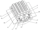
Fig. 2 is a first perspective view of the present invention.
Fig. 3 is a second perspective view of the present invention.
Fig. 4 is a partial structural view one of the present invention.
Fig. 5 is a second partial structural view of the present invention.
Fig. 6 is a third partial structural view of the present invention.
Fig. 7 is a partial structural view four of the present invention.
Fig. 8 is a partial structural view five of the present invention.
Fig. 9 is a partial structural view six of the present invention.
Fig. 10 is a view showing a part of the structure of the invention.
In the figure, 1, a support frame; 2. a carriage; 3. a support table; 4. a base plate; 5. a mold; 6. pressing a plate; 7. briquetting; 8. forming holes; 9. a material placing block; 10. a squeegee; 11. a sliding plate; 12. positioning a plate; 13. a stopper; 14. a fixing pin; 15. a pin slot; 16. fixing the rod; 17. a cushion pad; 18. a first spring; 19. a mating plate; 20. a matching block; 21. a material distributing cavity; 22. a first conduit; 23. a second pipe; 24. a first through hole; 25. a storage bin; 26. a third pipeline; 27. a fourth pipe; 28. a second feed through hole; 29. a master cylinder; 30. a fixed block; 31. and (7) positioning a groove.
Detailed Description
The following description of the embodiments of the present invention will be made in detail with reference to the accompanying drawings 1 to 10.
In the implementation of the invention, with reference to fig. 1-10, a static pressure baking-free brick forming mechanism includes a support frame 1, a sliding frame 2 is vertically and slidably connected to the support frame 1, a preset main hydraulic cylinder 30 is fixedly connected to the support frame 1, the main hydraulic cylinder 30 drives the sliding frame 2 to vertically slide, in this embodiment, the main hydraulic cylinder 30 is used as a driving power source for pressing and forming a brick, a support table 3 fixedly connected to the support frame 1 is disposed below the sliding frame 2, a bottom plate 4 is fitted on the support table 3, a mold 5 is vertically and slidably fitted on the bottom plate 4, the preset main hydraulic cylinder is preset, in the implementation, the bottom plate 4 is used as a standard component to be produced in a matching manner, and in the production, a plurality of bottom plates 4 are required to be matched, similarly, the mold 5 is also used as a standard component to be produced, but a cavity structure for forming is used in the mold 5, the product can be independently designed according to the brick shape of actual production, is preset, can be independently implemented during implementation and can also be implemented in a brick body manufacturing line, when the product is independently implemented, the support table 3 serves as a base for supporting and forming the forming mechanism to mainly play a supporting role, when the product is incorporated on the brick body manufacturing line, the height of the support table 3 needs to be consistent with the height of a conveyor belt, so that a bottom plate 4 conveyed from the conveyor belt can enter the support table 3, the support table 3 is preset, a plurality of roller groups are transversely and slidably connected with the support table 3, are connected through the transmission mechanism and are synchronously driven to rotate in the same direction, a second spring is arranged between the plurality of roller groups and the support table 3, and under the action of the second spring, the roller groups have smaller extrusion force on the bottom plate 4, so that when the bottom plate 4 just enters the support table 3, the bottom plate 4 is squeezed out of the roller group under the action of the conveyer belt, and then when the conveyer belt reduces the action of the conveyer belt on the bottom plate 4 and is not enough to drive the bottom plate 4 to continue to advance, the roller group can drive the bottom plate 4 to continue to advance until the bottom plate 4 is driven to a set position, in the process, a detection device for detecting the in-place of the bottom plate 4 is arranged, the detection device can adopt a common optical sensor to detect whether the bottom plate 4 is in place, meanwhile, a fixed block 30 is fixedly connected to the support table 3, and the fixed block 30 is in sliding fit with a positioning groove 31 formed in the mold 5, so that the bottom plate 4 is positioned in the sliding direction through the matching relation of the fixed block 30 and the positioning groove 31;
in the preset, a pressing plate 6 fixedly connected to the sliding frame 2 is matched above the grinding tool, pressing blocks 7 are arranged on the pressing plate 6, the pressing blocks 7 are correspondingly matched with forming holes 8 formed in the die 5, in the present embodiment, the shapes of the forming holes 8 can be designed according to the shapes of the required bricks, meanwhile, the shapes of the pressing blocks 7 are matched with the shapes of the forming holes 8, in the present embodiment, the pressing plate 6 is used as a structural member for directly extruding materials to extrude the materials into bricks, the side edges of the pressing blocks 7 are matched with discharging blocks 9, in the preset, in the present embodiment, inclined channels are formed in a plurality of the discharging blocks 9, so that the discharging of the materials entering the discharging blocks 9 can be met, the open ends of the inclined channels of the discharging blocks 9 face the side wall of the pressing block 7, and when the open ends of the pressing blocks 7 do not slide out of the side wall of the pressing blocks 7, the pressing block 7 will limit the outflow of the material from the inclined channel, after the discharging blocks 9 slide out of the range of the pressing block 7, the inclined channel is in an open state, and in the preset state, a plurality of discharging blocks 9 are connected together and driven by a linear driving mechanism to slide vertically, in the embodiment, the linear driving mechanism can adopt a hydraulic cylinder, a lead screw, an electric telescopic rod or an air cylinder and other common mechanisms, in the preset state, a plurality of radiotherapy blocks are driven by a pair of hydraulic cylinders to slide vertically, the pair of hydraulic cylinders are vertically arranged on the sliding frame 2, so that the plurality of discharging blocks 9 are driven by the hydraulic cylinders to slide vertically together, and the opening and closing of the inclined channel on the discharging blocks 9 are controlled, and in the preset state, in order to ensure the sealing property, rubber sleeves made of rubber are connected on the side surfaces, where the discharging blocks 9 are attached to the pressing block 7;
in this embodiment, it is assumed that during the production, the mold 5 is continuously used, and the formed brick body will be disposed on the bottom plate 4 for transportation, that is, when the product is produced, after the bottom plate 4 is in place, the mold 5 needs to be placed on the bottom plate 4, and then the operations of feeding, strickling, and extrusion forming are sequentially performed, that is, in the initial state in this embodiment, the mold 5 needs to be fixedly connected to the sliding frame 2, the mold 5 is driven by the sliding of the sliding frame 2 to be placed on the bottom plate 4, and it is preset that two matching plates 19 are longitudinally and drivingly connected to the sliding frame 2, in this embodiment, two common linear driving components such as an electric telescopic rod, an air cylinder, and a screw rod can be used to drive the two matching blocks 20, and the two matching plates 19 are matched with the matching blocks 20 fixedly connected to the mold 5, and are preset, the matching plate 19 and the matching block 20 are respectively provided with teeth capable of being matched with each other, when the driving matching block 20 extends out to contact with the matching block 20, the mold 5 is connected to the sliding frame 2 through the teeth on the matching plate 19 and the matching block 20, the sliding frame 2 can be driven to slide up and down, when the sliding plate 11 is retracted, the mold 5 is unlocked, it is preset, in this embodiment, a plurality of fixing rods 16 matched with the mold 5 are fixedly connected to the bottom plate 4 in a vertical direction, a cushion pad 17 is connected to the fixing rods 16 in a vertical sliding manner, a first spring 18 sleeved on the fixing rods 16 is arranged between the cushion pad 17 and the fixing rods 16, in an actual implementation, when in an initial state, the mold 5 and the sliding frame 2 are connected together and are in an initial state position, namely, a movable highest position, after the bottom plate 4 moves to a set position, the sliding frame 2 drives the die 5 to move downwards to a set feeding position, when the die 5 is located at the position, the die 5 is matched with the fixed rod 16, namely the fixed rod 16 penetrates into a slot clamped on the die 5, then the die 5 is unlocked, the die 5 compresses the first spring 18 to slide downwards under the action of self weight until the first spring falls onto the bottom plate 4, and the arrangement of the first spring 18 and the buffer pad 17 is preset only to ensure that the die 5 is stressed uniformly and has certain buffer capacity in the falling process, so that the die 5 can be ensured to fall onto the bottom plate 4 completely under the action of self gravity;
after the mold 5 is placed on the bottom plate 4, the loading operation is to be performed, in this embodiment, the loading operation is completed based on the sliding of the controlled material discharging block 9, when the leveling operation is performed, the existing method is all adopted to directly scrape off the material, the excessive material will be directly wasted, and in order to reduce the waste of the material, in this embodiment, a material distributing mechanism communicated with the loading mechanism is arranged in the sliding frame 2, the material distributing mechanism comprises a plurality of material distributing cavities 21 arranged in the sliding frame 2, and is preset, in this embodiment, the material distributing cavities 21 are matched with the scrapers 10 connected to the mold 5 in a longitudinal driving manner, and in the preset, the scrapers 10 are driven by a set of lead screw guide rod mechanism to longitudinally slide, and the scrapers 10 are initially located at the side far away from all the forming holes 8, so as to meet the requirement that the material in all the forming holes 8 is scraped through the sliding of the scrapers 10, in the process of scraping the material higher than the forming hole 8 by driving the scraper 10 to slide, the material piled up in the forming hole 8 close to the initial position of the scraper 10 will be driven by the scraper 10 to pass through the remaining forming holes 8 in sequence, in the process, if the material filled in the forming hole 8 far away from the scraper 10 is reduced, when the scraper 10 carries out scraping operation, the material filled in the forming holes 8 will be filled by the scraper 10, thereby reducing the material waste during feeding in the conventional forming machine, the preset specification of the distributing cavities 21 in the same row is the same, the specification size of the distributing cavity 21 closer to the initial position of the scraper 10 is larger, that is, the initial position of the scraper 10 is taken as the direction to extend towards the advancing direction of the scraper 10, the specification of the distributing cavities 21 in different rows will be reduced in sequence, it should be noted that the volume of the forming holes 8 can be calculated, in this embodiment, each forming hole 8 has one distributing cavity 21 for loading, and therefore, the material to be actually filled in the distributing cavity 21 can also be accurately calculated, and it is only necessary to ensure that the volume of the material filled in the distributing cavity 21 near the initial position of the scraper 10 is greater than the actual volume of the forming hole 8 and can be far compensated, and the volume of the material filled in the distributing cavity 21 far from the initial position of the scraper 10 can ensure that all the forming holes 8 can be filled with the material under the action of the scraper 10, but in this process, it is necessary to ensure that the distributing cavity 21 is not supplemented any more after the material injection is completed, so that the volume of the material filled in the distributing cavity 21 can be accurately determined, and it is also necessary to ensure that the blocking between the distributing block and the distributing cavity 21 can be performed, and the communicating operation can be performed only when the loading is performed;
preset, the powder mechanism further includes a storage bin 25 disposed on the support frame 1, the storage bin 25 is communicated with the material conveying belt to be filled with material, the storage bin 25 is communicated with a plurality of third pipelines 26 fixedly connected to the support frame 1, a plurality of fourth pipelines 27 fixedly connected to the carriage 2 are vertically and slidably connected to the third pipelines 26, a second through hole 28 is disposed on the fourth pipeline 27, it is preset that the fourth pipelines 27 are communicated with the plurality of distribution chambers 21 to feed the material to the distribution chambers 21, in actual implementation, because the carriage 2 needs to vertically slide, the distance between the carriage 2 and the support frame 1 will change, if a hose connection is adopted, the blockage may occur, in this embodiment, the third pipeline 26 and the fourth pipeline 27 are both made of hard material, plastic or aluminum material, the second through hole 28 is disposed on a side facing the third pipeline 26 and the storage bin 25, when the carriage 2 is in an initial position, that is in the carriage 2, that is in a moving position, when the carriage 2 is in the moving position, the opening of the fourth pipeline 26 is located at the upper position, the fourth pipeline 26 is not blocked, the opening of the fourth pipeline 26, the fourth pipeline 26 can be continuously moved, the fourth pipeline 26 is moved, the opening of the fourth pipeline 26 and the fourth pipeline 21, the fourth pipeline 26 can be continuously moved, the fourth pipeline 21, the fourth pipeline 26 is moved, the opening of the fourth pipeline 26 and the fourth pipeline 21, the fourth pipeline 21 can be moved, and the fourth pipeline 21, the fourth pipeline 26 can be continuously moved, and the fourth pipeline 21, the opening, the fourth pipeline 26 can be moved, and the fourth pipeline 21, and the opening can be prevented from being blocked, the fourth pipeline 21, the opening when the fourth pipeline 21, the fourth pipeline 21 can be moved, the fourth pipeline 26 is not blocked, the extension end of the upper end of the third pipeline 26 is larger than the fourth pipeline 27, so that a certain buffer area is ensured to be stored in the fourth pipeline 27, and blockage is avoided;
it is preset that the communication mode between the discharging block 9 and the distributing chamber 21 is similar to the communication mode between the distributing chamber 21 and the storage bin 25, that is, the side edges of a plurality of the distributing chambers 21 are communicated with a first pipeline 22 installed in the carriage 2, a second pipeline 23 communicated with the discharging block 9 is vertically and slidably connected in the first pipeline 22, a first material passing hole 24 is formed in the second pipeline 23, so that when the discharging block 9 is at a discharging position, that is, at a lowest position where the discharging block is located, the first material passing hole 24 is communicated with an opening of the first pipeline 22, at this time, the material in the distributing chamber 21 flows out from an inclined channel of the discharging block 9 and falls into the forming hole 8, after the feeding is completed, the discharging block 9 slides upwards under the driving of the auxiliary hydraulic cylinder, the inclined channel is firstly closed, then the first material passing hole 24 is not communicated with the first pipeline 22 along with the continuous rising of the discharging block 9, so that the second pipeline 23 is not communicated with the second pipeline 23, even if the distributing chamber 21 is opened again, the opening of the second pipeline 23 is larger than the opening of the second pipeline 23, and the opening of the second pipeline 23 is formed in the uppermost buffering chamber 23, the second pipeline 23, the uppermost opening of the second pipeline 23 is not opened, and the second pipeline 23 is not blocked, the uppermost buffering chamber 23, the second pipeline 23, the uppermost buffering chamber 23 is guaranteed, and the upper end of the second pipeline 23 is not blocked, the second pipeline 23, and the uppermost buffering chamber 23 is not blocked by the uppermost buffering chamber 23, the second pipeline 23 is not blocked area is not blocked;
in this embodiment, when the bottom plate 4 is loaded on the support platform 3, since the position of the discharge block 9 is fixed, the position that will cause the material to fall is fixed, in order to prevent the material from falling into the forming hole 8 too integrally, it is set that the mold 5 is driven by the shaking mechanism to slide repeatedly in the longitudinal direction, so that the material is distributed in the forming hole 8 without being too concentrated, the shaking mechanism includes two sliding plates 11 that are slidably connected to the support platform 3 in the longitudinal direction, the two sliding plates 11 are driven by the crank mechanism provided on the support platform 3 to slide reciprocally, and it is preset, in this embodiment, the crank mechanism used here is a common crank mechanism, i.e. a crank that is rotatably connected to the support platform 3 is driven by a servo motor, a pin is provided on the crank, the pin is slidably engaged with the sliding plates 11, so that the sliding plates 11 are driven to slide reciprocally by the rotation of the crank, the two sliding plates 11 are respectively vertically and telescopically connected with a positioning plate 12, in the same manner as the driving of the baffle, both plates 12 are driven by an electric telescopic rod, the bottom plate 4 is vertically slidably connected with the positioning plate 12, and the positioning plate 4 is detected by a stop block 14, and the positioning plate 4 is fixed on the bottom plate 4, and the positioning plate 4 is detected by a stop block 14, and the positioning plate is set on the bottom plate 4, roller train stop to rotate here afterwards and drive the motor that the roller train carries out the pivoted and should adopt the motor that does not take self-locking function, locating plate 12 is driven the cooperation that slides down through keyway 15 and fixed pin 14 will make bottom plate 4 be connected with locating plate 12, when locating plate 12 is driven to reciprocate to slide by the crank, locating plate 12 will drive bottom plate 4 together and carry out reciprocal slip on brace table 3, thereby make the material fall into the regional expansion in shaping hole 8, avoid the material to pile up too concentratedly.
When the method is implemented, the specific process is as follows: the bottom plate 4 slides on the support platform 3 under the driving of the roller group, in an initial state, the positioning plate 12 is at a position which can block the stop block 13 but can not be matched with the fixed pin 14, after the bottom plate 4 is detected to slide to the position blocked by the positioning plate 12, the positioning plate 12 slides downwards, the pin groove 15 is matched with the fixed pin 14, then the sliding frame 2 is driven by the main hydraulic cylinder 30 to slide downwards from the highest initial state position until the sliding frame slides to a set loading position, when the position is detected, the mould 5 is matched with the fixed rod 16 on the bottom plate 4, namely the fixed rod 16 enters the groove arranged on the mould 5, then the matching plate 19 is driven to slide and recover, then the mould 5 is unlocked, the mould 5 extrudes the first spring 18 to fall down on the bottom plate 4, and when the position is detected, the height of the pressing block 7 is completely separated from the forming hole 8 and is higher than the position of the scraper 10, then, the auxiliary hydraulic cylinder acts to slide the discharging block 9 downwards, then the material in the distributing cavity 21 falls into the forming hole 8 through the discharging block 9, and in the process, the crank acts to drive the mold 5 to slide in a reciprocating manner, so that the material accumulation is avoided being too concentrated, after the material in the distributing cavity 21 completely falls into the forming hole 8, the discharging block 9 returns to the initial state position, the scraper 10 is driven by a lead screw to scrape the material on the surface of the mold 5, namely the scraper 10 performs a reciprocating movement, then the sliding frame 2 continues to act and slide downwards by the main hydraulic cylinder 30, the pressing block 7 extrudes the material in the forming hole 8 to be extruded into bricks, namely the sliding frame 2 moves to the position contacting the mold 5, then the matching plate 19 extends out again to be matched with the matching block 20 to lock and connect the mold 5 and the sliding frame 2, then the sliding frame 2 returns to the initial state position under the driving of the main hydraulic cylinder 30, when the sliding frame 2 returns to the initial state position, the materials in the storage bin 25 enter the second pipeline 23 through the second through hole and finally refill the material distribution cavity 21, and then the next bottom plate 4 reaches the supporting table 3 to continue the operation for producing the brick body.
The above description is only for the purpose of illustrating the preferred embodiments of the present invention and should not be taken as limiting the scope of the present invention, which is intended to cover any modifications, equivalents, improvements, etc. within the spirit and scope of the present invention.
Claims (10)
1. The utility model provides a non-burning brick forming mechanism of static pressure, includes support frame (1), its characterized in that, vertical sliding connection has carriage (2) on support frame (1), carriage (2) below is put fixed connection and is equipped with brace table (3) on support frame (1), the cooperation has bottom plate (4) on brace table (3), vertical sliding fit has mould (5) on bottom plate (4), mould (5) are driven by the shake mechanism and are carried out fore-and-aft and slide repeatedly, the cooperation of grinding apparatus top has clamp plate (6) of fixed connection on carriage (2), it is provided with briquetting (7) to arrange on clamp plate (6), briquetting (7) correspond the cooperation with shaping hole (8) of seting up on mould (5), briquetting (7) side cooperation has blowing piece (9), and is a plurality of blowing piece (9) are common with the feed mechanism intercommunication of fixed connection in carriage (2), still include scraper blade (10) of longitudinal sliding connection on mould (5).
2. The static pressure baking-free brick molding mechanism according to claim 1, characterized in that the shaking mechanism comprises two sliding plates (11) longitudinally slidably connected to the supporting platform (3), the two sliding plates (11) are driven by a crank mechanism arranged on the supporting platform (3) to slide back and forth, the two sliding plates (11) are respectively vertically and telescopically connected with positioning plates (12), the two positioning plates (12) are respectively matched with a stop block (13) fixedly connected to the bottom plate (4), a fixed pin (14) fixedly connected to the bottom plate (4) is arranged on the side of the stop block (13), and the fixed pin (14) is matched with a pin groove (15) formed in the positioning plate (12).
3. The static pressure baking-free brick molding mechanism according to claim 2, characterized in that a plurality of fixing rods (16) matched with the mold (5) are fixedly connected to the bottom plate (4) vertically, a buffer pad (17) is slidably connected to the plurality of fixing rods (16) vertically, and a first spring (18) sleeved on the fixing rods (16) is arranged between the buffer pad (17) and the fixing rods (16).
4. The static pressure baking-free brick molding mechanism according to claim 2, wherein two matching plates (19) are connected to the sliding frame (2) in a longitudinal driving manner, and the two matching plates (19) are matched with matching blocks (20) fixedly connected to the mold (5) so as to meet the requirement that when the matching plates (19) extend, the matching blocks (20) are matched with each other, so that the sliding frame (2) drives the mold (5) to slide together.
5. The static pressure baking-free brick molding mechanism of claim 1, wherein the scraper (10) is driven by a screw-guide mechanism to slide longitudinally, and the scraper (10) is initially positioned at one side far away from all the molding holes (8) so as to scrape the materials in all the molding holes (8) through the sliding of the scraper (10).
6. The static-pressure baking-free brick molding mechanism according to claim 5, wherein the material distributing mechanism comprises a plurality of material distributing cavities (21) arranged in the sliding frame (2), the material distributing cavities (21) in the same row have the same specification, the larger the specification of the material distributing cavity (21) at the initial position of the scraper (10), the more the side of the material distributing cavity (21) is communicated with a first pipeline (22) arranged in the sliding frame (2), a second pipeline (23) communicated with the material placing block (9) is vertically and slidably connected in the first pipeline (22), and a first material passing hole (24) is formed in the second pipeline (23).
7. The static pressure baking-free brick molding mechanism according to claim 6, characterized in that the powder mechanism further comprises a storage bin (25) disposed on the support frame (1), the storage bin (25) is communicated with a plurality of third pipelines (26) fixedly connected to the support frame (1), a fourth pipeline (27) fixedly connected to the sliding frame (2) is vertically and slidably connected in the plurality of third pipelines (26), and a second through hole (28) is disposed on the fourth pipeline (27).
8. The static pressure baking-free brick molding mechanism according to claim 1 or 6, characterized in that a plurality of the discharging blocks (9) are connected together and driven by the linear driving mechanism to slide vertically.
9. The static pressure baking-free brick molding mechanism of claim 1 or 7, wherein the sliding frame (2) is driven by a main hydraulic cylinder (30) to slide vertically.
10. A static pressure non-burnt brick molding mechanism according to claim 3, characterized in that the supporting platform (3) is fixedly connected with a fixing block (30) which is arranged longitudinally, and the fixing block (30) is in sliding fit with a positioning groove (31) which is arranged on the bottom plate (4).
Priority Applications (1)
| Application Number | Priority Date | Filing Date | Title |
|---|---|---|---|
| CN202210860574.0A CN115179410B (en) | 2022-07-22 | 2022-07-22 | Static pressure baking-free brick forming mechanism |
Applications Claiming Priority (1)
| Application Number | Priority Date | Filing Date | Title |
|---|---|---|---|
| CN202210860574.0A CN115179410B (en) | 2022-07-22 | 2022-07-22 | Static pressure baking-free brick forming mechanism |
Publications (2)
| Publication Number | Publication Date |
|---|---|
| CN115179410A true CN115179410A (en) | 2022-10-14 |
| CN115179410B CN115179410B (en) | 2023-07-14 |
Family
ID=83519220
Family Applications (1)
| Application Number | Title | Priority Date | Filing Date |
|---|---|---|---|
| CN202210860574.0A Active CN115179410B (en) | 2022-07-22 | 2022-07-22 | Static pressure baking-free brick forming mechanism |
Country Status (1)
| Country | Link |
|---|---|
| CN (1) | CN115179410B (en) |
Cited By (1)
| Publication number | Priority date | Publication date | Assignee | Title |
|---|---|---|---|---|
| CN116551814A (en) * | 2023-04-27 | 2023-08-08 | 浙江弼土新材料股份有限公司 | Building garbage recycling and brick making integrated equipment and processing technology thereof |
Citations (26)
| Publication number | Priority date | Publication date | Assignee | Title |
|---|---|---|---|---|
| FR365658A (en) * | 1906-04-24 | 1906-09-14 | James J Cox | Molding machines for building bricks and stones |
| WO1986000042A1 (en) * | 1984-06-08 | 1986-01-03 | Siegfried Geitlinger | Method and plant for fabricating building blocks with a swellable material in a multicavity mould |
| EP0262278A1 (en) * | 1986-10-01 | 1988-04-06 | André Accetta | Machine for producing building blocks of stabilized earth |
| EP0749815A1 (en) * | 1995-06-21 | 1996-12-27 | Franz Carl Nüdling Basaltwerke GmbH & Co. KG | Moulded article with inlays and process and apparatus for making it |
| JP2002011716A (en) * | 2000-06-30 | 2002-01-15 | Takasago Tile Kk | Apparatus for charging pottery stock in mold |
| WO2003022543A1 (en) * | 2001-09-07 | 2003-03-20 | Guoquan Huang | Double-distribution unit and method for forming ceramic tiles and products obtained thereby |
| CN106956354A (en) * | 2017-01-06 | 2017-07-18 | 林凯锋 | A kind of ceramic brick feeding device and method |
| CN206544246U (en) * | 2017-02-27 | 2017-10-10 | 天津市龙建丰液压机械有限公司 | A kind of non-burning brick brickmaking brick discharging system |
| CN207206714U (en) * | 2017-09-26 | 2018-04-10 | 重庆鸿基木业有限公司 | A kind of quartzy stone platform production line |
| CN108908655A (en) * | 2018-07-28 | 2018-11-30 | 南通瑞强机械制造有限公司 | A kind of brick pressing device for brickmaking machine |
| CN209304765U (en) * | 2018-07-21 | 2019-08-27 | 山东东风双隆机械有限公司 | A kind of novel concrete block machine fabric distribution device |
| CN110405914A (en) * | 2018-04-28 | 2019-11-05 | 台山市河朗新型环保建材有限公司 | A kind of compression molding device of novel large Concrete brick |
| CN209851188U (en) * | 2018-07-28 | 2019-12-27 | 南通瑞强机械制造有限公司 | Brick pressing device for brick making machine |
| EP3597385A1 (en) * | 2018-07-20 | 2020-01-22 | Kvm Industrimaskiner A/S | Mould for concrete blocks with (large) level differences, such as kerbstones/blocks/lock stones with or without cavities/drain |
| CN110883908A (en) * | 2019-11-08 | 2020-03-17 | 福建群峰机械有限公司 | Forming mechanism of brick machine |
| CN110919843A (en) * | 2019-12-27 | 2020-03-27 | 昆山市惠盛实业有限公司 | Baking-free brick production device |
| CN112339102A (en) * | 2020-11-06 | 2021-02-09 | 泉州市益鑫机械科技有限公司 | Supporting plate-free brick making machine |
| CN112388817A (en) * | 2020-12-16 | 2021-02-23 | 遵义汉丰装饰材料有限责任公司 | Semi-dry method static pressure forming building block production line |
| CN213533065U (en) * | 2020-09-18 | 2021-06-25 | 刘钊 | Baking-free brick forming die |
| CN213971745U (en) * | 2020-10-14 | 2021-08-17 | 舞钢市恒润达新型建材有限公司 | Multifunctional brick making mold |
| KR102325583B1 (en) * | 2021-05-25 | 2021-11-11 | 조민현 | Automatic retaining wall block manufacturing device with improved productivity |
| CN215038516U (en) * | 2021-06-18 | 2021-12-07 | 山东天康恒达科技有限公司 | Full-automatic extrusion equipment |
| CN215150134U (en) * | 2021-07-16 | 2021-12-14 | 江苏胤昊新材料科技有限公司 | Extrusion shaping equipment for processing light partition boards |
| CN114055602A (en) * | 2021-11-10 | 2022-02-18 | 安庆惠嘉新型建材有限公司 | Auxiliary device for red brick die-casting |
| CN215943278U (en) * | 2021-07-08 | 2022-03-04 | 郑州科技学院 | Brick making device for producing solid waste fine material |
| CN114516108A (en) * | 2022-02-24 | 2022-05-20 | 胡佳彤 | Novel brick making machine |
-
2022
- 2022-07-22 CN CN202210860574.0A patent/CN115179410B/en active Active
Patent Citations (27)
| Publication number | Priority date | Publication date | Assignee | Title |
|---|---|---|---|---|
| FR365658A (en) * | 1906-04-24 | 1906-09-14 | James J Cox | Molding machines for building bricks and stones |
| WO1986000042A1 (en) * | 1984-06-08 | 1986-01-03 | Siegfried Geitlinger | Method and plant for fabricating building blocks with a swellable material in a multicavity mould |
| EP0262278A1 (en) * | 1986-10-01 | 1988-04-06 | André Accetta | Machine for producing building blocks of stabilized earth |
| EP0749815A1 (en) * | 1995-06-21 | 1996-12-27 | Franz Carl Nüdling Basaltwerke GmbH & Co. KG | Moulded article with inlays and process and apparatus for making it |
| JP2002011716A (en) * | 2000-06-30 | 2002-01-15 | Takasago Tile Kk | Apparatus for charging pottery stock in mold |
| WO2003022543A1 (en) * | 2001-09-07 | 2003-03-20 | Guoquan Huang | Double-distribution unit and method for forming ceramic tiles and products obtained thereby |
| CN1466508A (en) * | 2001-09-07 | 2004-01-07 | 黄国权 | Ceramic tile composite material distributing equipment and distributing method, produced products thereof |
| CN106956354A (en) * | 2017-01-06 | 2017-07-18 | 林凯锋 | A kind of ceramic brick feeding device and method |
| CN206544246U (en) * | 2017-02-27 | 2017-10-10 | 天津市龙建丰液压机械有限公司 | A kind of non-burning brick brickmaking brick discharging system |
| CN207206714U (en) * | 2017-09-26 | 2018-04-10 | 重庆鸿基木业有限公司 | A kind of quartzy stone platform production line |
| CN110405914A (en) * | 2018-04-28 | 2019-11-05 | 台山市河朗新型环保建材有限公司 | A kind of compression molding device of novel large Concrete brick |
| EP3597385A1 (en) * | 2018-07-20 | 2020-01-22 | Kvm Industrimaskiner A/S | Mould for concrete blocks with (large) level differences, such as kerbstones/blocks/lock stones with or without cavities/drain |
| CN209304765U (en) * | 2018-07-21 | 2019-08-27 | 山东东风双隆机械有限公司 | A kind of novel concrete block machine fabric distribution device |
| CN108908655A (en) * | 2018-07-28 | 2018-11-30 | 南通瑞强机械制造有限公司 | A kind of brick pressing device for brickmaking machine |
| CN209851188U (en) * | 2018-07-28 | 2019-12-27 | 南通瑞强机械制造有限公司 | Brick pressing device for brick making machine |
| CN110883908A (en) * | 2019-11-08 | 2020-03-17 | 福建群峰机械有限公司 | Forming mechanism of brick machine |
| CN110919843A (en) * | 2019-12-27 | 2020-03-27 | 昆山市惠盛实业有限公司 | Baking-free brick production device |
| CN213533065U (en) * | 2020-09-18 | 2021-06-25 | 刘钊 | Baking-free brick forming die |
| CN213971745U (en) * | 2020-10-14 | 2021-08-17 | 舞钢市恒润达新型建材有限公司 | Multifunctional brick making mold |
| CN112339102A (en) * | 2020-11-06 | 2021-02-09 | 泉州市益鑫机械科技有限公司 | Supporting plate-free brick making machine |
| CN112388817A (en) * | 2020-12-16 | 2021-02-23 | 遵义汉丰装饰材料有限责任公司 | Semi-dry method static pressure forming building block production line |
| KR102325583B1 (en) * | 2021-05-25 | 2021-11-11 | 조민현 | Automatic retaining wall block manufacturing device with improved productivity |
| CN215038516U (en) * | 2021-06-18 | 2021-12-07 | 山东天康恒达科技有限公司 | Full-automatic extrusion equipment |
| CN215943278U (en) * | 2021-07-08 | 2022-03-04 | 郑州科技学院 | Brick making device for producing solid waste fine material |
| CN215150134U (en) * | 2021-07-16 | 2021-12-14 | 江苏胤昊新材料科技有限公司 | Extrusion shaping equipment for processing light partition boards |
| CN114055602A (en) * | 2021-11-10 | 2022-02-18 | 安庆惠嘉新型建材有限公司 | Auxiliary device for red brick die-casting |
| CN114516108A (en) * | 2022-02-24 | 2022-05-20 | 胡佳彤 | Novel brick making machine |
Cited By (1)
| Publication number | Priority date | Publication date | Assignee | Title |
|---|---|---|---|---|
| CN116551814A (en) * | 2023-04-27 | 2023-08-08 | 浙江弼土新材料股份有限公司 | Building garbage recycling and brick making integrated equipment and processing technology thereof |
Also Published As
| Publication number | Publication date |
|---|---|
| CN115179410B (en) | 2023-07-14 |
Similar Documents
| Publication | Publication Date | Title |
|---|---|---|
| CN101130260A (en) | Equipment for pressing large-scale ultra-thin porcelain plate and pressing method thereof | |
| CN110962217A (en) | Ceramic cup lug extrusion molding machine | |
| CN111531793B (en) | Injection molding device for wine box base production | |
| CN106313297B (en) | A kind of device for automatically molding for non-burning brick production | |
| CN115179410A (en) | Static pressure baking-free brick forming mechanism | |
| CN107932971B (en) | Pressing production system for extrusion molding product | |
| CN108215060A (en) | A kind of automatic hose shoulder-injection machine | |
| CN116922543B (en) | Mortar material conveying and forming device | |
| CN112388817A (en) | Semi-dry method static pressure forming building block production line | |
| CN113306003A (en) | Block forming machine | |
| CN219926423U (en) | Novel baked brick make-up machine | |
| CN218227165U (en) | Brick pressing equipment for refractory brick production | |
| CN112339071B (en) | Baked brick production is with integration equipment is cut with quick shaping | |
| CN215241566U (en) | Combined shale hollow brick processing device | |
| CN214293675U (en) | A accurate distributing device for machine is pressed refractory material | |
| CN210551978U (en) | Two-way extrusion formula brickmaking machine convenient to adjust brickmaking size | |
| CN210477620U (en) | Injection molding machine feed mechanism | |
| CN210045960U (en) | Full-automatic wet clay sand core making machine | |
| CN113618879B (en) | Downward-pressing type hydraulic brick press | |
| CN109227894B (en) | Mold box circulation system with supporting plate | |
| CN208468894U (en) | A kind of automatic hose shoulder-injection machine | |
| CN220614386U (en) | Isostatic press for producing ceramics | |
| CN214082048U (en) | Semi-dry method static pressure forming building block production line | |
| CN212097272U (en) | Injection molding machine loading attachment | |
| CN217621991U (en) | Double-screw demoulding device for applying glue |
Legal Events
| Date | Code | Title | Description |
|---|---|---|---|
| PB01 | Publication | ||
| PB01 | Publication | ||
| SE01 | Entry into force of request for substantive examination | ||
| SE01 | Entry into force of request for substantive examination | ||
| GR01 | Patent grant | ||
| GR01 | Patent grant |