CN114515410B - A recovered pedal device for sports apparatus - Google Patents
A recovered pedal device for sports apparatus Download PDFInfo
- Publication number
- CN114515410B CN114515410B CN202210016730.5A CN202210016730A CN114515410B CN 114515410 B CN114515410 B CN 114515410B CN 202210016730 A CN202210016730 A CN 202210016730A CN 114515410 B CN114515410 B CN 114515410B
- Authority
- CN
- China
- Prior art keywords
- rotating arm
- machine body
- left rotating
- rod
- electric push
- Prior art date
- Legal status (The legal status is an assumption and is not a legal conclusion. Google has not performed a legal analysis and makes no representation as to the accuracy of the status listed.)
- Active
Links
Images


Classifications
-
- A—HUMAN NECESSITIES
- A63—SPORTS; GAMES; AMUSEMENTS
- A63B—APPARATUS FOR PHYSICAL TRAINING, GYMNASTICS, SWIMMING, CLIMBING, OR FENCING; BALL GAMES; TRAINING EQUIPMENT
- A63B22/00—Exercising apparatus specially adapted for conditioning the cardio-vascular system, for training agility or co-ordination of movements
- A63B22/06—Exercising apparatus specially adapted for conditioning the cardio-vascular system, for training agility or co-ordination of movements with support elements performing a rotating cycling movement, i.e. a closed path movement
- A63B22/0605—Exercising apparatus specially adapted for conditioning the cardio-vascular system, for training agility or co-ordination of movements with support elements performing a rotating cycling movement, i.e. a closed path movement performing a circular movement, e.g. ergometers
-
- A—HUMAN NECESSITIES
- A63—SPORTS; GAMES; AMUSEMENTS
- A63B—APPARATUS FOR PHYSICAL TRAINING, GYMNASTICS, SWIMMING, CLIMBING, OR FENCING; BALL GAMES; TRAINING EQUIPMENT
- A63B21/00—Exercising apparatus for developing or strengthening the muscles or joints of the body by working against a counterforce, with or without measuring devices
- A63B21/005—Exercising apparatus for developing or strengthening the muscles or joints of the body by working against a counterforce, with or without measuring devices using electromagnetic or electric force-resisters
- A63B21/0056—Exercising apparatus for developing or strengthening the muscles or joints of the body by working against a counterforce, with or without measuring devices using electromagnetic or electric force-resisters using electromagnetically-controlled friction, e.g. magnetic particle brakes
-
- A—HUMAN NECESSITIES
- A63—SPORTS; GAMES; AMUSEMENTS
- A63B—APPARATUS FOR PHYSICAL TRAINING, GYMNASTICS, SWIMMING, CLIMBING, OR FENCING; BALL GAMES; TRAINING EQUIPMENT
- A63B22/00—Exercising apparatus specially adapted for conditioning the cardio-vascular system, for training agility or co-ordination of movements
- A63B22/06—Exercising apparatus specially adapted for conditioning the cardio-vascular system, for training agility or co-ordination of movements with support elements performing a rotating cycling movement, i.e. a closed path movement
- A63B22/0605—Exercising apparatus specially adapted for conditioning the cardio-vascular system, for training agility or co-ordination of movements with support elements performing a rotating cycling movement, i.e. a closed path movement performing a circular movement, e.g. ergometers
- A63B2022/0611—Particular details or arrangement of cranks
-
- A—HUMAN NECESSITIES
- A63—SPORTS; GAMES; AMUSEMENTS
- A63B—APPARATUS FOR PHYSICAL TRAINING, GYMNASTICS, SWIMMING, CLIMBING, OR FENCING; BALL GAMES; TRAINING EQUIPMENT
- A63B2208/00—Characteristics or parameters related to the user or player
- A63B2208/02—Characteristics or parameters related to the user or player posture
- A63B2208/0228—Sitting on the buttocks
-
- A—HUMAN NECESSITIES
- A63—SPORTS; GAMES; AMUSEMENTS
- A63B—APPARATUS FOR PHYSICAL TRAINING, GYMNASTICS, SWIMMING, CLIMBING, OR FENCING; BALL GAMES; TRAINING EQUIPMENT
- A63B2225/00—Miscellaneous features of sport apparatus, devices or equipment
- A63B2225/09—Adjustable dimensions
- A63B2225/093—Height
Landscapes
- Health & Medical Sciences (AREA)
- Physics & Mathematics (AREA)
- Electromagnetism (AREA)
- General Health & Medical Sciences (AREA)
- Physical Education & Sports Medicine (AREA)
- Life Sciences & Earth Sciences (AREA)
- Biophysics (AREA)
- Orthopedic Medicine & Surgery (AREA)
- Cardiology (AREA)
- Vascular Medicine (AREA)
- Rehabilitation Tools (AREA)
Abstract
The invention relates to the technical field of sports equipment, and discloses a rehabilitation pedal device for the sports equipment, which comprises a base, a machine body, an inner groove, a left rotating arm and a cushion, wherein the machine body is provided with a left rotating arm and a right rotating arm; the organism is fixed on the top surface of base, and the organism is located the left side on base surface, the inside groove is transversely seted up at the inside intermediate position of organism, and the inside horizontal rotatable transfer line of installing of organism of inside groove department, the outside of the both ends of transfer line all run through to the organism, the transfer line outer lane in the inside groove encircles and is fixed with annular magnet. The pedals are arranged on the left rotating arm and the right rotating arm, so that the pedals can be adsorbed and locked at one ends of the left rotating arm and the right rotating arm under the action of the second electromagnet, leg training of a simulated bicycle can be performed, the left rotating arm and the right rotating arm are locked when the second electromagnet changes the current direction to repel the magnet block, the rehabilitation training during leg treading action can be realized, patients can conveniently perform different types of rehabilitation training, and the occupied area of equipment is reduced.
Description
Technical Field
The invention relates to the technical field of sports equipment, in particular to a rehabilitation pedal device for the sports equipment.
Background
At present, sports equipment is a general name of various instruments, equipment and articles used in sports competition and body-building exercise, the sports equipment and the sports are interdependent and mutually promoted, the popularization of the sports and the diversification of sports items enable the types, specifications and the like of the sports equipment to be developed, the sports equipment mainly refers to equipment used in the competition and the body exercise, and after a plurality of patients with leg injuries are treated in bed for a long time, leg muscles shrink, the patients cannot normally move, and the legs need to be trained adaptively.
Traditional shank trainer simulation is stepped on the bicycle and is trained, perhaps reciprocates and steps on the footboard that has resistance and train the shank, and the training mode is single reciprocating motion or single rotation of trampling, in order to realize mutually supporting of two kinds of training modes, needs switch over the training between two kinds of equipment, inconvenient removal when the patient moves inconveniently, still has the too big problem of equipment area occupied simultaneously. Therefore, we propose a rehabilitation footrest for a sports apparatus.
Disclosure of Invention
The invention aims to provide a rehabilitation pedal device for sports equipment, which is characterized in that pedals are arranged on a left rotating arm and a right rotating arm, the pedals can be adsorbed and locked at one ends of the left rotating arm and the right rotating arm under the action of a second electromagnet, then leg training of a simulated bicycle can be carried out, when the second electromagnet changes a current direction to repel a magnet block, the left rotating arm and the right rotating arm are locked, the rehabilitation training during leg treading action can be realized, patients can conveniently carry out different types of rehabilitation training, and the occupied area of equipment is reduced.
In order to achieve the purpose, the invention provides the following technical scheme: a rehabilitation pedal device for sports equipment comprises a base, a machine body, an inner groove, a left rotating arm and a cushion; the machine body is fixed on the upper surface of the base and is positioned on the left side of the surface of the base;
the inner groove is transversely formed in the middle of the inside of the machine body, a transmission rod is transversely and rotatably arranged in the machine body at the position of the inner groove, two ends of the transmission rod penetrate through the outside of the machine body, an annular magnet is fixed on the outer ring of the transmission rod in the inner groove in a surrounding manner and is arranged in the inner groove, and first electromagnets are embedded in the machine body above and below the inner groove;
the left rotating arm is mounted at the tail end of a transmission rod at the front end of the machine body, the tail end of the transmission rod at the rear end of the machine body is provided with a right rotating arm, a sliding groove is vertically formed in the inner part of the left rotating arm, a spring is arranged below the inner part of the sliding groove, a vertical groove is vertically formed in the surface of the left rotating arm at the outer side of the sliding groove and is communicated with the outer part of the left rotating arm and the inner part of the sliding groove, a second electromagnet is embedded in the left rotating arm above the sliding groove, a magnet block is slidably arranged in the sliding groove below the second electromagnet, the left side of the magnet block is fixedly connected with a rotating rod, the rotating rod penetrates through the outer part of the left rotating arm through the vertical groove, a pedal is rotatably mounted at the tail end of the rotating rod and is attached to the surface of the left rotating arm, first electric push rods are mounted on the upper surface and the lower surface of the left rotating arm, the end of each first electric push rod is located on the inner side of the left rotating arm, the structure of the right rotating arm is the same as that of the left rotating arm, the right rotating arm is centrally symmetrical to the center of the left rotating arm, and the lower surface of the left rotating arm and the lower surface of the right rotating arm at the rear end of the left rotating arm, and the right rotating arm are respectively provided with jacks;
the cushion transversely sets up the base surface on organism right side, and the cushion is on a parallel with the surface of base, and the cushion passes through the pillar and installs the top at the base, and the top right side surface embedding of organism installs the operation control screen.
In a preferred embodiment of the present invention, a second electric push rod is fixedly fitted into the upper portion of the inside of the support column, the upper portion of the second electric push rod extends above the support column, the top portion of the second electric push rod is supported below the seat cushion, and the second electric push rod is connected to the operation control panel.
As a preferred embodiment of the present invention, a handle is supported and fixed on the upper portion of the right side of the machine body through a support rod, and the handle is parallel to the upper surface of the machine body below.
In a preferred embodiment of the present invention, the width of the vertical groove is smaller than the width of the slide groove, the width of the magnet block is larger than the width of the vertical groove, and the width of the magnet block is smaller than the width of the slide groove.
In a preferred embodiment of the present invention, the transmission rod is rotatably connected to the machine body through a first bearing, and the first bearing is embedded into the surface of the machine body.
In a preferred embodiment of the present invention, the pedal is rotatably connected to the end of the rotating rod via a second bearing, and the second bearing is embedded in the pedal.
As a preferred embodiment of the invention, the support bar is supported and fixed at the middle position below the grip, and the support bar is vertically arranged on the upper surface of the machine body.
As a preferred embodiment of the present invention, the first electric push rod, the first electromagnet and the second electromagnet are all electrically connected to the operation control panel.
Compared with the prior art, the invention has the following beneficial effects:
1. according to the rehabilitation pedal device for the sports equipment, the pedals are arranged on the left rotating arm and the right rotating arm, the pedals can be adsorbed and locked at one ends of the left rotating arm and the right rotating arm under the action of the second electromagnet, then leg training of a bicycle can be simulated, when the second electromagnet changes the current direction to repel the magnet blocks, the left rotating arm and the right rotating arm are locked, the rehabilitation training during leg pedaling can be realized, a patient can conveniently perform different types of rehabilitation training, and the occupied area of equipment is reduced.
2. According to the rehabilitation pedal device for the sports equipment, the second electric push rod is embedded and fixed above the inner part of the support column, the upper part of the second electric push rod penetrates above the support column, the top part of the second electric push rod is supported below the cushion, and when a patient sits on the cushion for training, the height of the cushion can be changed by the lifting of the second electric push rod, so that the requirements of the patient on different height sitting postures are met.
3. According to the rehabilitation pedal device for the sports equipment, the handle is supported and fixed on the upper portion of the right side of the machine body through the support rod and is parallel to the upper surface of the machine body below, and a patient can hold the handle by the hand during training through the arrangement of the handle on the upper portion of the machine body, so that the effect of stable supporting is provided.
4. According to the rehabilitation pedal device for the sports equipment, the width of the vertical groove is smaller than that of the sliding groove, the width of the magnet block is larger than that of the vertical groove, and the width of the magnet block is smaller than that of the sliding groove, so that the magnet block cannot fall off from the sliding groove when sliding smoothly in the sliding groove, and the connection stability is ensured.
Drawings
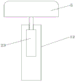
FIG. 1 is a schematic view of the overall construction of a rehabilitation pedal device for sporting equipment according to the present invention;
FIG. 2 is a schematic cross-sectional view of the body of the rehabilitation pedal device for sports equipment of the present invention;
FIG. 3 is a schematic view of the pedal connecting structure of the rehabilitation pedal device for sports apparatus according to the present invention;
fig. 4 is a schematic view of a cushion mounting structure of the rehabilitation pedal device for sports equipment of the present invention.
In the drawings, labeled as: 1. a base; 2. a body; 3. an inner tank; 4. a left rotating arm; 5. a cushion; 6. a jack; 7. a pedal; 8. a first electric push rod; 9. operating the control screen; 10. a strut; 11. a grip; 12. a pillar; 13. a vertical slot; 14. a right rotating arm; 15. a ring magnet; 16. a first electromagnet; 17. a second electromagnet; 18. a transmission rod; 19. a chute; 20. a spring; 21. a rotating rod; 22. a magnet block; 23. a second electric push rod; 24. a first bearing; 25. a second bearing.
Detailed Description
The technical solutions in the embodiments of the present invention will be clearly and completely described below with reference to the drawings in the embodiments of the present invention, but the technical solutions do not limit the scope of the present invention.
Referring to fig. 1-4, the present invention provides a technical solution: a rehabilitation pedal device for sports equipment comprises a base 1, a machine body 2, an inner groove 3, a left rotating arm 4 and a cushion 5; the machine body 2 is fixed on the upper surface of the base 1, and the machine body 2 is positioned on the left side of the surface of the base 1;
the inner groove 3 is transversely arranged in the middle of the inside of the machine body 2, a transmission rod 18 is transversely and rotatably arranged in the machine body 2 at the position of the inner groove 3, two ends of the transmission rod 18 penetrate through the outside of the machine body 2, an annular magnet 15 is fixed on the outer ring of the transmission rod 18 in the inner groove 3 in a surrounding manner, the annular magnet is arranged in the inner groove 3, and first electromagnets 16 are embedded in the machine body 2 above and below the inner groove 3;
the left rotating arm 4 is installed at the tail end of a transmission rod 18 at the front end of the machine body 2, the tail end of the transmission rod 18 at the rear end of the machine body 2 is provided with a right rotating arm 14, a sliding groove 19 is vertically formed in the left rotating arm 4, a spring 20 is arranged below the inner part of the sliding groove 19, a vertical groove 13 is vertically formed in the surface of the left rotating arm 4 on the outer side of the sliding groove 19, the vertical groove 13 is communicated with the outer part of the left rotating arm 4 and the inner part of the sliding groove 19, a second electromagnet 17 is embedded in the left rotating arm 4 above the sliding groove 19, a magnet block 22 is slidably arranged in the sliding groove 19 below the second electromagnet 17, the left side of the magnet block 22 is fixedly connected with a rotating rod 21, the rotating rod 21 penetrates through the vertical groove 13 to the outer part of the left rotating arm 4, the tail end of the rotating rod 21 is rotatably provided with a pedal 7, the pedal 7 is attached to the surface of the left rotating arm 4, a first electric push rod 8 is installed on the upper surface and the lower surface of the left rotating arm 4, the extending end of the first electric push rod 8 is positioned on the inner side of the left rotating arm 4, the right rotating arm 14 is identical to the structure of the left rotating arm 4, the right rotating arm 14, the right rotating arm is symmetrically arranged with the center of the machine body 2, and the left rotating arm, and the jack 6;
In the invention, when in use, the machine body 2 is stably supported on the ground through the base 1, when in training, the equipment is firstly connected to a power supply, then a patient sits on the seat cushion 5 for rehabilitation training, when in simulated bicycle training, the second electromagnet 17 is firstly controlled to be electrified to be magnetic, and then the magnet block 22 is closely adsorbed to be close to the tail end of the sliding groove 19, so that the pedal 7 on the outer side of the left rotating arm 4 is movably fixed to the upper surface, the pedal 7 on the outer side of the right rotating arm 14 is movably fixed to the lower surface, then the feet of the patient can step on the pedals 7 on one side of the left rotating arm 4 and one side of the right rotating arm 14, the left rotating arm 4 and the right rotating arm 14 are subjected to stepping movement to drive the transmission rod 18 to rotate, the transmission rod 18 drives the annular magnet 15 to rotate in the inner groove 3, the aim of leg training of the patient is achieved, during training, the current inside the first electromagnet 16 is controlled, and the magnetic size of the first electromagnet 16 can be changed, and the magnetic force of the annular magnet 15 is different to the resistance of stepping; when the patient only needs to do reciprocating treading training, the left rotating arm 4 and the right rotating arm 14 can be rotated to the inclined positions at the front end of the insertion hole 6, the extending end of the first electric push rod 8 is positioned at the insertion hole 6, the first electric push rod 8 is controlled to extend and insert the extending end of the first electric push rod 8 into the insertion hole 6, the left rotating arm 4 and the right rotating arm 14 are locked, so that the left rotating arm 4 and the right rotating arm 14 cannot rotate, then the direction of current led into the second electromagnet 17 is changed, the current inside the second electromagnet 17 is reduced, the second electromagnet 17 can repel the magnet block 22 with small force, then the leg of the patient is treaded on the pedal 7, the pedal 7 is treaded in a reciprocating mode, the purposes of compressing the spring 20 and overcoming the movement of the second electromagnet 17 are achieved, when the spring 20 is compressed, resistance is provided for the block 22 on the inner side of the pedal 7 through the second electromagnet, and rehabilitation training during treading action of the leg can be achieved.
In an alternative embodiment, a second electric push rod 23 is embedded and fixed above the inside of the support column 12, the second electric push rod 23 extends above the support column 12, the top of the second electric push rod 23 is supported below the seat cushion 5, and the second electric push rod 23 is connected with the operation control screen 9, in this embodiment (see fig. 4), the second electric push rod 23 is embedded and fixed above the inside of the support column 12, the second electric push rod 23 extends above the support column 12, and the top of the second electric push rod 23 is supported below the seat cushion 5, when a patient sits on the seat cushion 5 for training, the height of the seat cushion 5 can be changed by the second electric push rod 23 being lifted, so as to meet the needs of different height sitting postures of the patient.
In an alternative embodiment, a handle 11 is supported and fixed on the upper right side of the machine body 2 through a support rod 10, and the handle 11 is parallel to the upper surface of the machine body 2 below, in this embodiment (see fig. 1), the handle 11 is supported and fixed on the upper right side of the machine body 2 through the support rod 10, and the handle 11 is parallel to the upper surface of the machine body 2 below, and by the arrangement of the handle 11 on the machine body 2, a patient can hold the handle 11 with his hand during training, so as to provide a stable holding effect.
In an alternative embodiment, the width of the vertical groove 13 is smaller than the width of the sliding groove 19, the width of the magnet block 22 is larger than the width of the vertical groove 13, and the width of the magnet block 22 is smaller than the width of the sliding groove 19, in this embodiment (see fig. 1 and 2), the width of the vertical groove 13 is smaller than the width of the sliding groove 19, the width of the magnet block 22 is larger than the width of the vertical groove 13, and the width of the magnet block 22 is smaller than the width of the sliding groove 19, so that the magnet block 22 cannot fall off from the sliding groove 19 when sliding smoothly inside the sliding groove 19, and the connection stability is ensured.
In an alternative embodiment, the transmission rod 18 is rotatably connected to the machine body 2 through a first bearing 24, and the first bearing 24 is embedded into the surface of the machine body 2, in this embodiment (see fig. 1), the transmission rod 18 is rotatably connected to the machine body 2 through the first bearing 24.
In an alternative embodiment, the pedal 7 is rotatably connected to the end of the rotating rod 21 through a second bearing 25, and the second bearing 25 is embedded inside the pedal 7, in this embodiment (see fig. 2), the rotatable connection between the pedal 7 and the rotating rod 21 is realized through the second bearing 25.
In an alternative embodiment, the support rod 10 is supported and fixed at a middle position below the handle 11, and the support rod 10 is vertically disposed on the upper surface of the machine body 2, in this embodiment (see fig. 1), the support rod 10 is supported at the middle portion below the handle 11, so as to provide a relatively stable supporting effect.
In an alternative embodiment, the first electric push rod 8, the first electromagnet 16, and the second electromagnet 17 are all electrically connected to the operation control panel 9, and in this embodiment (see fig. 1 and 2), the first electric push rod 8, the first electromagnet 16, and the second electromagnet 17 are controlled by the operation control panel 9.
It should be noted that the present invention is a rehabilitation pedal device for sports equipment, which comprises a base 1, a body 2, an inner groove 3, a left rotating arm 4, a cushion 5, a jack 6, a pedal 7, a first electric push rod 8, an operation control panel 9, a support rod 10, a handle 11, a pillar 12, a vertical groove 13, a right rotating arm 14, a ring magnet 15, a first electromagnet 16, a second electromagnet 17, a transmission rod 18, a sliding groove 19, a spring 20, a rotating rod 21, a magnet block 22, a second electric push rod 23, a first bearing 24, and a second bearing 25, which are all common standard components or components known to those skilled in the art, and the structure and principle of which are known to those skilled in the art through technical manuals or through conventional experimental methods.
While the foregoing is directed to the preferred embodiment of the present invention, it will be understood by those skilled in the art that various changes and modifications may be made without departing from the spirit and scope of the invention.
Claims (8)
1. A rehabilitation pedal device for sports equipment is characterized by comprising a base (1), a machine body (2), an inner groove (3), a left rotating arm (4) and a cushion (5); the machine body (2) is fixed on the upper surface of the base (1), and the machine body (2) is positioned on the left side of the surface of the base (1);
the inner groove (3) is transversely formed in the middle of the inside of the machine body (2), a transmission rod (18) is transversely and rotatably mounted in the machine body (2) at the position of the inner groove (3), two ends of the transmission rod (18) penetrate through the outside of the machine body (2), an annular magnet (15) is fixedly wound on the outer ring of the transmission rod (18) in the inner groove (3) in a surrounding mode, the annular magnet is arranged in the inner groove (3), and first electromagnets (16) are embedded in the machine body (2) above and below the inner groove (3);
the left rotating arm (4) is installed at the tail end of a transmission rod (18) at the front end of the machine body (2), a right rotating arm (14) is installed at the tail end of the transmission rod (18) at the rear end of the machine body (2), a sliding groove (19) is vertically formed in the inner portion of the left rotating arm (4), a spring (20) is arranged below the inner portion of the sliding groove (19), a vertical groove (13) is vertically formed in the surface of the left rotating arm (4) at the outer side of the sliding groove (19), the vertical groove (13) is communicated with the outer portion of the left rotating arm (4) and the inner portion of the sliding groove (19), a second electromagnet (17) is installed in the inner portion of the left rotating arm (4) above the sliding groove (19), a magnet block (22) can be arranged in the sliding groove (19) below the second electromagnet (17) in a sliding mode, a rotating rod (21) is fixedly connected to the left side of the magnet block (22), the rotating rod (21) penetrates through the outer portion of the left rotating arm (4) through the vertical groove (13), a pedal (7) is installed at the tail end of the rotating rod (21), the left rotating arm (7) is attached to the surface of the left rotating arm (4), a first rotating arm (8) is installed on the surface, and a left rotating arm (8) is located on the inner side of an electric push rod (8) on the inner side of the left rotating arm (4), and a left rotating arm (8), the right rotating arm (14) is centrosymmetric with the left rotating arm (4) by the central position of the machine body (2), and the surfaces of the lower left side and the lower right side of the front end and the rear end of the machine body (2) are provided with jacks (6);
when reciprocating trampling training is required, the left rotating arm and the right rotating arm are rotated to the inclined positions at the front ends of the jacks, the extending end of the first electric push rod is positioned at the jacks, the first electric push rod is controlled to extend and insert the extending end of the first electric push rod into the jacks, and the left rotating arm and the right rotating arm are locked and cannot rotate;
cushion (5) transversely set up base (1) surface on organism (2) right side, and cushion (5) are on a parallel with the surface of base (1), and install in the top of base (1) through pillar (12) cushion (5), and operation control screen (9) are installed to the top right side surface embedding of organism (2).
2. A rehabilitation pedal device for sports apparatus according to claim 1, characterized in that: a second electric push rod (23) is fixedly embedded in the upper portion of the inner portion of the support column (12), the upper portion of the second electric push rod (23) penetrates through the upper portion of the support column (12), the top portion of the second electric push rod (23) is supported below the seat cushion (5), and the second electric push rod (23) is connected with the operation control screen (9).
3. A rehabilitation pedal device for sports apparatus according to claim 1, characterized in that: a handle (11) is supported and fixed on the upper part of the right side of the machine body (2) through a support rod (10), and the handle (11) is parallel to the upper surface of the machine body (2) below.
4. A rehabilitation pedal device for sports apparatuses according to claim 1, characterized in that: the width of the vertical groove (13) is smaller than that of the sliding groove (19), the width of the magnet block (22) is larger than that of the vertical groove (13), and the width of the magnet block (22) is smaller than that of the sliding groove (19).
5. A rehabilitation pedal device for sports apparatus according to claim 1, characterized in that: the transmission rod (18) is rotatably connected with the machine body (2) through a first bearing (24), and the first bearing (24) is embedded into the surface of the machine body (2).
6. A rehabilitation pedal device for sports apparatus according to claim 1, characterized in that: the pedal (7) is rotatably connected with the tail end of the rotating rod (21) through a second bearing (25), and the second bearing (25) is embedded in the pedal (7).
7. A rehabilitation pedal device for sports apparatuses according to claim 3, characterized in that: the support rod (10) is supported and fixed at the middle position below the grip (11), and the support rod (10) is vertically arranged on the upper surface of the machine body (2).
8. A rehabilitation pedal device for sports apparatus according to claim 1, characterized in that: the first electric push rod (8), the first electromagnet (16) and the second electromagnet (17) are electrically connected with the operation control screen (9).
Priority Applications (1)
| Application Number | Priority Date | Filing Date | Title |
|---|---|---|---|
| CN202210016730.5A CN114515410B (en) | 2022-01-07 | 2022-01-07 | A recovered pedal device for sports apparatus |
Applications Claiming Priority (1)
| Application Number | Priority Date | Filing Date | Title |
|---|---|---|---|
| CN202210016730.5A CN114515410B (en) | 2022-01-07 | 2022-01-07 | A recovered pedal device for sports apparatus |
Publications (2)
| Publication Number | Publication Date |
|---|---|
| CN114515410A CN114515410A (en) | 2022-05-20 |
| CN114515410B true CN114515410B (en) | 2023-03-03 |
Family
ID=81597351
Family Applications (1)
| Application Number | Title | Priority Date | Filing Date |
|---|---|---|---|
| CN202210016730.5A Active CN114515410B (en) | 2022-01-07 | 2022-01-07 | A recovered pedal device for sports apparatus |
Country Status (1)
| Country | Link |
|---|---|
| CN (1) | CN114515410B (en) |
Citations (20)
| Publication number | Priority date | Publication date | Assignee | Title |
|---|---|---|---|---|
| US4792135A (en) * | 1987-08-03 | 1988-12-20 | Chin Sen Chiu | Compound multi-function gym benches |
| US5514053A (en) * | 1992-06-17 | 1996-05-07 | Hawkins; Tranel | Recumbent pedal exerciser |
| US5735774A (en) * | 1995-07-19 | 1998-04-07 | Maresh; Joseph Douglas | Active crank axis cycle mechanism |
| DE20202828U1 (en) * | 2002-01-22 | 2002-08-01 | Chen, Chih-liang, Pateh, Taoyuan | Damping device for a training bike |
| JP2007330732A (en) * | 2006-06-12 | 2007-12-27 | Norimitsu Shiromoto | Bicycle type training apparatus |
| KR20130053960A (en) * | 2011-11-16 | 2013-05-24 | 김범준 | Cycle athletic apparatus |
| CN205924861U (en) * | 2016-07-30 | 2017-02-08 | 南阳医学高等专科学校第一附属医院 | Lower limbs rehabilitation training apparatus |
| CN109876375A (en) * | 2019-03-28 | 2019-06-14 | 北华大学 | A kind of sport athletic training equipment |
| CN209048997U (en) * | 2018-10-24 | 2019-07-02 | 毕节医学高等专科学校 | A kind of athlete's leg strength training equipment |
| CN210251033U (en) * | 2019-06-04 | 2020-04-07 | 天津健坤润德体育用品股份有限公司 | Lower limb rehabilitation training vehicle |
| CN111790112A (en) * | 2020-07-21 | 2020-10-20 | 刘继兰 | Multi-functional medical rehabilitation trainer |
| CN212067583U (en) * | 2019-12-24 | 2020-12-04 | 安徽医科大学第一附属医院 | Knee joint recovery device with exercise effect for oncology department |
| CN212395333U (en) * | 2020-09-14 | 2021-01-26 | 哈尔滨奈卓生物技术有限公司 | Portable nanometer thermal magnetic therapy automatic hemiplegic rehabilitation machine |
| CN212880797U (en) * | 2020-07-15 | 2021-04-06 | 陈琳琳 | Recovered shank exercise device of using |
| CN112932903A (en) * | 2021-03-15 | 2021-06-11 | 陈小平 | Cerebral apoplexy rehabilitation exercise device |
| CN113082612A (en) * | 2021-05-11 | 2021-07-09 | 刘陶志 | Orthopedics medical treatment rehabilitation training device with supplementary structure of taking exercise of ankle joint |
| CN214344181U (en) * | 2021-01-31 | 2021-10-08 | 西安翻译学院 | Physical training device is used in sports teaching |
| CN214436238U (en) * | 2021-03-04 | 2021-10-22 | 靖刚 | Leg muscle exercising device for bone fracture rehabilitation training |
| CN113750454A (en) * | 2021-10-18 | 2021-12-07 | 李红 | Leg exercise system for rehabilitation department |
| CN215310033U (en) * | 2021-06-11 | 2021-12-28 | 张香花 | Obstetrical nursing exercise equipment |
Family Cites Families (3)
| Publication number | Priority date | Publication date | Assignee | Title |
|---|---|---|---|---|
| US6688192B1 (en) * | 1999-05-06 | 2004-02-10 | Ziad Badarneh | Pedal device |
| CN201389289Y (en) * | 2009-04-03 | 2010-01-27 | 厦门奥龙体育器材有限公司 | Swing surfing machine |
| KR20100110938A (en) * | 2009-04-06 | 2010-10-14 | 김영모 | Low body traing apparatus for chair sitter |
-
2022
- 2022-01-07 CN CN202210016730.5A patent/CN114515410B/en active Active
Patent Citations (20)
| Publication number | Priority date | Publication date | Assignee | Title |
|---|---|---|---|---|
| US4792135A (en) * | 1987-08-03 | 1988-12-20 | Chin Sen Chiu | Compound multi-function gym benches |
| US5514053A (en) * | 1992-06-17 | 1996-05-07 | Hawkins; Tranel | Recumbent pedal exerciser |
| US5735774A (en) * | 1995-07-19 | 1998-04-07 | Maresh; Joseph Douglas | Active crank axis cycle mechanism |
| DE20202828U1 (en) * | 2002-01-22 | 2002-08-01 | Chen, Chih-liang, Pateh, Taoyuan | Damping device for a training bike |
| JP2007330732A (en) * | 2006-06-12 | 2007-12-27 | Norimitsu Shiromoto | Bicycle type training apparatus |
| KR20130053960A (en) * | 2011-11-16 | 2013-05-24 | 김범준 | Cycle athletic apparatus |
| CN205924861U (en) * | 2016-07-30 | 2017-02-08 | 南阳医学高等专科学校第一附属医院 | Lower limbs rehabilitation training apparatus |
| CN209048997U (en) * | 2018-10-24 | 2019-07-02 | 毕节医学高等专科学校 | A kind of athlete's leg strength training equipment |
| CN109876375A (en) * | 2019-03-28 | 2019-06-14 | 北华大学 | A kind of sport athletic training equipment |
| CN210251033U (en) * | 2019-06-04 | 2020-04-07 | 天津健坤润德体育用品股份有限公司 | Lower limb rehabilitation training vehicle |
| CN212067583U (en) * | 2019-12-24 | 2020-12-04 | 安徽医科大学第一附属医院 | Knee joint recovery device with exercise effect for oncology department |
| CN212880797U (en) * | 2020-07-15 | 2021-04-06 | 陈琳琳 | Recovered shank exercise device of using |
| CN111790112A (en) * | 2020-07-21 | 2020-10-20 | 刘继兰 | Multi-functional medical rehabilitation trainer |
| CN212395333U (en) * | 2020-09-14 | 2021-01-26 | 哈尔滨奈卓生物技术有限公司 | Portable nanometer thermal magnetic therapy automatic hemiplegic rehabilitation machine |
| CN214344181U (en) * | 2021-01-31 | 2021-10-08 | 西安翻译学院 | Physical training device is used in sports teaching |
| CN214436238U (en) * | 2021-03-04 | 2021-10-22 | 靖刚 | Leg muscle exercising device for bone fracture rehabilitation training |
| CN112932903A (en) * | 2021-03-15 | 2021-06-11 | 陈小平 | Cerebral apoplexy rehabilitation exercise device |
| CN113082612A (en) * | 2021-05-11 | 2021-07-09 | 刘陶志 | Orthopedics medical treatment rehabilitation training device with supplementary structure of taking exercise of ankle joint |
| CN215310033U (en) * | 2021-06-11 | 2021-12-28 | 张香花 | Obstetrical nursing exercise equipment |
| CN113750454A (en) * | 2021-10-18 | 2021-12-07 | 李红 | Leg exercise system for rehabilitation department |
Also Published As
| Publication number | Publication date |
|---|---|
| CN114515410A (en) | 2022-05-20 |
Similar Documents
| Publication | Publication Date | Title |
|---|---|---|
| CN111760249B (en) | Intelligent control multifunctional combined body-building training equipment and training control method | |
| CN207996396U (en) | A kind of autonomous training device of Neurology | |
| CN110917563B (en) | Weight-bearing body-building facility and weight-bearing operation method | |
| NL1006270C2 (en) | Exercise machine with variable configuration. | |
| CN212262245U (en) | Multifunctional strength training instrument | |
| CN114515410B (en) | A recovered pedal device for sports apparatus | |
| CN111643852B (en) | Waist exerciser | |
| US7955231B1 (en) | Physical exercising machine | |
| CN116212315A (en) | Shank muscle stretching training ware is used in sports teaching of convenient regulation elasticity | |
| CN215691374U (en) | Cardiovascular internal medicine nursing is with recovered ware | |
| CN110368643B (en) | Knee and shoulder joint simultaneous exercise rehabilitation device | |
| KR20140052148A (en) | Sit-up bench | |
| CN210813749U (en) | Body-building sports physical training device | |
| CN211659162U (en) | Front-back swinging single-rod multifunctional body-building device | |
| CN111616920A (en) | Intelligent rehabilitation nursing machine based on big data | |
| CN216456718U (en) | Slide rail pedal | |
| CN111494874A (en) | Multifunctional strength training instrument | |
| CN2829799Y (en) | Riding horse machine | |
| CN114259696B (en) | Exercise bicycle of rehabilitation branch of academic or vocational study | |
| US7955232B1 (en) | Physical exercising machine | |
| CN215741634U (en) | Limb rehabilitation training device for nursing in burn plastic surgery | |
| CN108992844B (en) | Body-building equipment for mine staff | |
| CN220833552U (en) | Lower limb rehabilitation chair | |
| CN215427171U (en) | Shank trainer that track and field sports used | |
| CN217745590U (en) | Recovered branch of academic or vocational study is with arm muscle exercise equipment |
Legal Events
| Date | Code | Title | Description |
|---|---|---|---|
| PB01 | Publication | ||
| PB01 | Publication | ||
| SE01 | Entry into force of request for substantive examination | ||
| SE01 | Entry into force of request for substantive examination | ||
| GR01 | Patent grant | ||
| GR01 | Patent grant |