CN114482225A - Be used for soil and water to keep ecological remediation to administer device - Google Patents
Be used for soil and water to keep ecological remediation to administer device Download PDFInfo
- Publication number
- CN114482225A CN114482225A CN202210144094.4A CN202210144094A CN114482225A CN 114482225 A CN114482225 A CN 114482225A CN 202210144094 A CN202210144094 A CN 202210144094A CN 114482225 A CN114482225 A CN 114482225A
- Authority
- CN
- China
- Prior art keywords
- water
- soil
- fixed
- extends
- pipe
- Prior art date
- Legal status (The legal status is an assumption and is not a legal conclusion. Google has not performed a legal analysis and makes no representation as to the accuracy of the status listed.)
- Pending
Links
- XLYOFNOQVPJJNP-UHFFFAOYSA-N water Substances O XLYOFNOQVPJJNP-UHFFFAOYSA-N 0.000 title claims abstract description 172
- 239000002689 soil Substances 0.000 title claims abstract description 48
- 238000005067 remediation Methods 0.000 title claims description 13
- 238000004140 cleaning Methods 0.000 claims abstract description 33
- 238000003973 irrigation Methods 0.000 claims abstract description 10
- 230000002262 irrigation Effects 0.000 claims abstract description 10
- 239000004568 cement Substances 0.000 claims description 28
- 238000009434 installation Methods 0.000 claims description 22
- 230000000087 stabilizing effect Effects 0.000 claims description 21
- 244000309464 bull Species 0.000 claims description 13
- 238000002955 isolation Methods 0.000 claims description 5
- 230000010405 clearance mechanism Effects 0.000 claims 2
- 238000001914 filtration Methods 0.000 abstract description 10
- 238000005507 spraying Methods 0.000 abstract description 3
- 239000010410 layer Substances 0.000 description 56
- 238000005192 partition Methods 0.000 description 11
- 239000007921 spray Substances 0.000 description 6
- 241001464837 Viridiplantae Species 0.000 description 5
- 230000005540 biological transmission Effects 0.000 description 2
- 230000000694 effects Effects 0.000 description 2
- 239000012466 permeate Substances 0.000 description 2
- 230000001681 protective effect Effects 0.000 description 2
- 239000000956 alloy Substances 0.000 description 1
- 229910045601 alloy Inorganic materials 0.000 description 1
- 230000009286 beneficial effect Effects 0.000 description 1
- 239000004927 clay Substances 0.000 description 1
- 238000010586 diagram Methods 0.000 description 1
- 239000000428 dust Substances 0.000 description 1
- 230000004048 modification Effects 0.000 description 1
- 238000012986 modification Methods 0.000 description 1
- 239000010813 municipal solid waste Substances 0.000 description 1
- 238000004162 soil erosion Methods 0.000 description 1
- 239000002344 surface layer Substances 0.000 description 1
Images


Classifications
-
- E—FIXED CONSTRUCTIONS
- E03—WATER SUPPLY; SEWERAGE
- E03F—SEWERS; CESSPOOLS
- E03F1/00—Methods, systems, or installations for draining-off sewage or storm water
-
- A—HUMAN NECESSITIES
- A01—AGRICULTURE; FORESTRY; ANIMAL HUSBANDRY; HUNTING; TRAPPING; FISHING
- A01G—HORTICULTURE; CULTIVATION OF VEGETABLES, FLOWERS, RICE, FRUIT, VINES, HOPS OR SEAWEED; FORESTRY; WATERING
- A01G25/00—Watering gardens, fields, sports grounds or the like
- A01G25/02—Watering arrangements located above the soil which make use of perforated pipe-lines or pipe-lines with dispensing fittings, e.g. for drip irrigation
-
- B—PERFORMING OPERATIONS; TRANSPORTING
- B01—PHYSICAL OR CHEMICAL PROCESSES OR APPARATUS IN GENERAL
- B01D—SEPARATION
- B01D29/00—Filters with filtering elements stationary during filtration, e.g. pressure or suction filters, not covered by groups B01D24/00 - B01D27/00; Filtering elements therefor
- B01D29/01—Filters with filtering elements stationary during filtration, e.g. pressure or suction filters, not covered by groups B01D24/00 - B01D27/00; Filtering elements therefor with flat filtering elements
- B01D29/03—Filters with filtering elements stationary during filtration, e.g. pressure or suction filters, not covered by groups B01D24/00 - B01D27/00; Filtering elements therefor with flat filtering elements self-supporting
-
- B—PERFORMING OPERATIONS; TRANSPORTING
- B01—PHYSICAL OR CHEMICAL PROCESSES OR APPARATUS IN GENERAL
- B01D—SEPARATION
- B01D29/00—Filters with filtering elements stationary during filtration, e.g. pressure or suction filters, not covered by groups B01D24/00 - B01D27/00; Filtering elements therefor
- B01D29/50—Filters with filtering elements stationary during filtration, e.g. pressure or suction filters, not covered by groups B01D24/00 - B01D27/00; Filtering elements therefor with multiple filtering elements, characterised by their mutual disposition
- B01D29/56—Filters with filtering elements stationary during filtration, e.g. pressure or suction filters, not covered by groups B01D24/00 - B01D27/00; Filtering elements therefor with multiple filtering elements, characterised by their mutual disposition in series connection
-
- B—PERFORMING OPERATIONS; TRANSPORTING
- B01—PHYSICAL OR CHEMICAL PROCESSES OR APPARATUS IN GENERAL
- B01D—SEPARATION
- B01D29/00—Filters with filtering elements stationary during filtration, e.g. pressure or suction filters, not covered by groups B01D24/00 - B01D27/00; Filtering elements therefor
- B01D29/62—Regenerating the filter material in the filter
- B01D29/64—Regenerating the filter material in the filter by scrapers, brushes, nozzles, or the like, acting on the cake side of the filtering element
- B01D29/6407—Regenerating the filter material in the filter by scrapers, brushes, nozzles, or the like, acting on the cake side of the filtering element brushes
- B01D29/6423—Regenerating the filter material in the filter by scrapers, brushes, nozzles, or the like, acting on the cake side of the filtering element brushes with a translational movement with respect to the filtering element
-
- E—FIXED CONSTRUCTIONS
- E02—HYDRAULIC ENGINEERING; FOUNDATIONS; SOIL SHIFTING
- E02D—FOUNDATIONS; EXCAVATIONS; EMBANKMENTS; UNDERGROUND OR UNDERWATER STRUCTURES
- E02D17/00—Excavations; Bordering of excavations; Making embankments
- E02D17/20—Securing of slopes or inclines
-
- E—FIXED CONSTRUCTIONS
- E03—WATER SUPPLY; SEWERAGE
- E03F—SEWERS; CESSPOOLS
- E03F5/00—Sewerage structures
- E03F5/10—Collecting-tanks; Equalising-tanks for regulating the run-off; Laying-up basins
-
- E—FIXED CONSTRUCTIONS
- E03—WATER SUPPLY; SEWERAGE
- E03F—SEWERS; CESSPOOLS
- E03F5/00—Sewerage structures
- E03F5/10—Collecting-tanks; Equalising-tanks for regulating the run-off; Laying-up basins
- E03F5/101—Dedicated additional structures, interposed or parallel to the sewer system
-
- E—FIXED CONSTRUCTIONS
- E03—WATER SUPPLY; SEWERAGE
- E03F—SEWERS; CESSPOOLS
- E03F5/00—Sewerage structures
- E03F5/14—Devices for separating liquid or solid substances from sewage, e.g. sand or sludge traps, rakes or grates
-
- E—FIXED CONSTRUCTIONS
- E03—WATER SUPPLY; SEWERAGE
- E03F—SEWERS; CESSPOOLS
- E03F5/00—Sewerage structures
- E03F5/22—Adaptations of pumping plants for lifting sewage
-
- E—FIXED CONSTRUCTIONS
- E03—WATER SUPPLY; SEWERAGE
- E03F—SEWERS; CESSPOOLS
- E03F7/00—Other installations or implements for operating sewer systems, e.g. for preventing or indicating stoppage; Emptying cesspools
Abstract
The invention relates to the technical field of ecological restoration treatment equipment, in particular to a device for water and soil conservation ecological restoration treatment. The technical scheme comprises the following steps: the bottom, the upper end fixed mounting of bottom has the install bin, and logical groove has been seted up to the slope wall of install bin, be equipped with retaining spare in the install bin, retaining spare includes water storage tank and downcomer a. According to the invention, through setting of the ecological restoration treatment equipment, the ecological restoration treatment equipment has the functions of water filtering, cleaning, irrigation, drainage and the like, and the water filtering function and the drainage function are combined, so that the cleanness of water stored in the water storage tank is ensured, and the situations of clogging and water pump damage are effectively avoided; the cleaning function, the water filtering function and the drainage function are combined, and the water filtering function and the drainage function are protected through the cleaning function so as to ensure the sustainability of water filtering and drainage; the spraying function and the drainage function are combined, so that the circular irrigation capacity is realized, and the water and soil running condition is avoided.
Description
Technical Field
The invention relates to the technical field of ecological restoration treatment equipment, in particular to a device for water and soil conservation ecological restoration treatment.
Background
The prior Chinese patent with the publication number of CN213625618U discloses an ecological slope protection for water and soil conservation, which is characterized in that a water storage pool, a water pump, a drainage tube, a spray head, a first water inlet groove and a water outlet pipe a are arranged, in practical application, a water source can be collected through the matching of the above steps, so that green plants are irrigated when the rainfall is less, the purpose of high-efficiency utilization of the water source is achieved, the practicability of the device is improved, meanwhile, under the action of the drainage tube, when the water source is too much, the water source can be discharged, the trouble of too much water source in the device is avoided, in practical application, through the arrangement of a cement layer, an alloy plate, green plants, bolts, threaded columns, a fixed plate and a positioning rod, under the premise that the green plants keep water and soil loss through the matching of the above steps, the lower end of a soil layer can be extruded and fixed, the water and soil loss rate is reduced, thereby reaching the control effect of improving the device on the water and soil loss.
Although the comparison documents collect rainwater, the protection net is not arranged, rainwater in rainy seasons can enter the water storage tank along with soil, dust, garbage and the like, so that not only can the water pump be damaged, but also the water storage tank can be silted up; simultaneously, a large amount of water also can be stored at rainwater weather in the second intake chamber, and water can enter into the soil horizon, because of there is not the drainage function, water can be from inside impact soil horizon, causes soil erosion and water loss.
Disclosure of Invention
The invention aims to solve the problems that a collecting irrigation device without a protection function, a soil layer without a drainage function and the like exist in the background art, and provides a multifunctional device for water and soil conservation ecological restoration and treatment.
The technical scheme of the invention is as follows: a device for ecological restoration and treatment of soil and water conservation comprises a bottom layer, wherein an installation box is fixedly installed at the upper end of the bottom layer, a through groove is formed in the slope wall of the installation box, a water storage part is arranged in the installation box and comprises a water storage tank and a sewer pipe a, a partition plate is installed in the water storage tank, a mud layer is arranged on the right side of the water storage part, the right end of the mud layer extends into the through groove, a stabilizing plate is arranged on the right side of the mud layer, the left end of the stabilizing plate is fixedly connected with the right end of the water storage tank, a filter screen b installed at the upper end of the water storage tank is arranged on the left side of the stabilizing plate, an isolation layer is jointly arranged above the filter screen b and the stabilizing plate, an irrigation mechanism and a cleaning mechanism are arranged in the water storage part, the cleaning mechanism comprises a cleaning assembly a, a cleaning assembly b and a driving assembly, a ground layer is arranged at the upper end of the installation box, a water storage groove is installed at the upper end of the ground layer, and the water storage tank is communicated with the water storage part, and a filter screen a is arranged in the water storage tank.
Preferably, irrigate the water pump that the mechanism includes that the baffle below sets up, the end of intaking of water pump is fixed with inlet tube an to the upper end of water pipe a extends to the baffle top and installs the filter screen, the play water end of water pump is fixed with outlet pipe an, and outlet pipe an's upper end extends to the baffle top, outlet pipe an's top is equipped with the water pipe b that is vertical setting, and water pipe b's upper end is fixed with a plurality of water pipe an that communicate with each other and set up, and water pipe an's upper end extends to the catch basin top, water pipe a's right-hand member is fixed with the shower nozzle, and the shower nozzle is located the catch basin right side.
Preferably, the rear end of the water pipe b is sealed, and the front end of the water pipe b is fixedly connected with the water inlet pipe a through an external hose.
Preferably, clearance subassembly a includes the reciprocal lead screw an that the longitudinal rotation connects in the water storage box, and reciprocal lead screw a is located filter screen b's below, reciprocal lead screw a goes up to be equipped with movable sleeve a through ball nut cover, and movable sleeve a's upper end is fixed with clearance brush an, and the department of meeting of upper end and filter screen b of clearance brush an, reciprocal lead screw a's right side is equipped with the spout of seting up in the inside right wall of water storage box, and sliding connection has the slider in the spout, and the left end of slider passes through quarter butt an and movable sleeve a fixed connection.
Preferably, the cleaning assembly b comprises a reciprocating screw rod b which is longitudinally and rotatably connected in the sewer pipe a, a movable sleeve b is sleeved on the reciprocating screw rod b through a ball nut, an L-shaped rod is fixed at the right end of the movable sleeve b, a convex groove which is arranged on the top wall in the installation box is formed in the upper portion of the L-shaped rod, a convex block is connected in the convex groove in a sliding mode, the lower end of the convex block is fixedly connected with the upper end of the L-shaped rod, a cleaning brush b is fixed at the upper end of the movable sleeve b through a short rod b, the upper end of the cleaning brush b is connected with the lower end of the filter screen a in a connecting mode, a worm wheel b which is fixedly sleeved on the reciprocating screw rod b is arranged on the rear side of the movable sleeve b, the left end of the worm wheel b is connected with a worm b in a meshing mode, and the upper end of the worm b is rotatably connected with the top wall in the installation box.
Preferably, drive assembly includes the driving motor that the baffle below set up, and driving motor's output is fixed with bull stick an, and bull stick an's upper end extends to the baffle top through waterproof bearing, bull stick a's upper end is fixed with worm an, and worm an's upper end rotates with the inside roof of water storage box to be connected, worm an's right-hand member meshing is connected with worm wheel an, and worm wheel an cover establish be fixed in reciprocal lead screw an on, fixed cover is equipped with belt pulley an on the bull stick an, and belt pulley an's left side is connected with belt pulley b through belt transmission, and belt pulley b's upper end is fixed with bull stick b, and bull stick b and worm b fixed connection.
Preferably, the below of firm board is equipped with cement layer a, be fixed with cement layer c between the inner wall left wall of install bin and the left side wall of retaining, be fixed with cement layer b between the slope wall of install bin and the inside bottom of install bin, and the right-hand member and the install bin inner wall fixed connection of cement layer b.
Preferably, be equipped with the drain pipe in the cement layer b, the left end of arranging the water pipe side by side extends to in the earth layer, and the right-hand member of earth layer extends to the right side of cement layer b.
Preferably, the right end of the cement layer a is fixed with a stabilizing frame, and the right end of the stabilizing frame extends to the right side of the soil layer.
Preferably, the ground floor upper end has been seted up and has been indulged the groove, indulges the inslot and install the honeycomb duct, and the lower extreme of honeycomb duct extends to in the earth layer, the top of baffle is equipped with the aqueduct, and the left end of aqueduct extends to the install bin left end.
Compared with the prior art, the invention has the following beneficial technical effects:
by setting the ecological restoration treatment equipment, the ecological restoration treatment equipment has the functions of water filtering, cleaning, irrigation, water drainage and the like, and is combined with the water filtering function and the water drainage function, so that the cleanness of water stored in the water storage tank is ensured, and the situations of clogging and water pump damage are effectively avoided; the cleaning function, the water filtering function and the drainage function are combined, and the water filtering function and the drainage function are protected through the cleaning function so as to ensure the sustainability of water filtering and drainage; the spraying function and the drainage function are combined, so that the circular irrigation capacity is realized, and the water and soil running condition is avoided.
Drawings
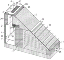
FIG. 1 is a schematic diagram of the structure of one embodiment of the present invention;
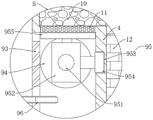
FIG. 2 is a front cross-sectional structural view of FIG. 1;
FIG. 3 is an enlarged schematic view of the structure at A in FIG. 2;
fig. 4 is an enlarged schematic view of a portion B in fig. 2.
Reference numerals: 1. a bottom layer; 2. installing a box; 3. a ground layer; 4. a water storage member; 5. a water storage tank; 6. a filter screen a; 7. a partition plate; 8. an irrigation mechanism; 81. a water pump; 82. a water pipe a; 83. a spray head; 84. a water pipe b; 9. a cleaning mechanism; 91. a drive motor; 92. a rotating rod a; 93. a worm a; 94. a worm wheel a; 95. cleaning the component a; 951. a reciprocating screw rod a; 952. a movable sleeve a; 953. a chute; 954. a slider; 955. cleaning brushes a; 96. a belt pulley a; 97. a belt pulley b; 98. a rotating rod b; 99. a cleaning component b; 991. a worm b; 992. a worm wheel b; 993. a reciprocating screw rod b; 994. a movable sleeve b; 995. a cleaning brush b; 996. a convex groove; 997. a bump; 998. an L-shaped rod; 10. an isolation layer; 11. a filter screen b; 12. a cement layer a; 13. a stabilizing frame; 14. a stabilizing plate; 15. a layer of clay; 16. a flow guide pipe; 17. a cement layer b; 18. a drain pipe; 19. a water conduit; 20. and (c) a cement layer.
Detailed Description
The technical solution of the present invention is further explained with reference to the accompanying drawings and specific embodiments.
Example one
As shown in figures 1, 2, 3 and 4, the invention provides a device for ecological restoration and treatment of soil and water conservation, which comprises a bottom layer 1, wherein an installation box 2 is fixedly installed at the upper end of the bottom layer 1, a through groove is formed in the slope wall of the installation box 2, a water storage part 4 is arranged in the installation box 2, the water storage part 4 comprises a water storage box and a downcomer a, the lower end of the water storage box is fixedly connected with the inner bottom end of the installation box 2, the upper end of the downcomer a is fixedly connected with the inner top wall of the installation box 2, a partition plate 7 is installed in the water storage box, a soil layer 15 is arranged on the right side of the water storage part 4, the right end of the soil layer 15 extends into the through groove, a stabilizing plate 14 is arranged on the right side of the soil layer 15, the left end of the stabilizing plate 14 is fixedly connected with the right end of the water storage box, the stabilizing plate 14 can protect the soil layer 15 to avoid the loss of the soil layer 15, a filter screen b11 installed at the upper end of the stabilizing plate 14 is arranged on the left side of the water storage box, an isolation layer 10 is arranged above the filter screen b11 and the stabilizing plate 14 together, an irrigation mechanism 8 and a cleaning mechanism 9 are arranged in the water storage part 4, wherein the cleaning mechanism 9 comprises a cleaning component a95, a cleaning component b99 and a driving component, the cleaning component a95 comprises a reciprocating screw rod a951 which is longitudinally and rotatably connected in the water storage tank, the reciprocating screw rod a951 is positioned below the filter screen b11, a movable sleeve a952 is sleeved on the reciprocating screw rod a951 through a ball nut, a cleaning brush a955 is fixed at the upper end of the movable sleeve a952, the upper end of the cleaning brush a955 is connected with the lower end of the filter screen b11, a chute 953 which is arranged on the right wall in the water storage tank is arranged at the right side of the reciprocating screw rod a951, a sliding block 954 is slidably connected in the chute 953, the left end of the sliding block 954 is fixedly connected with the movable sleeve a952 through a short rod a, the cleaning component b99 comprises a reciprocating screw rod b 3 which is longitudinally and rotatably connected in the sewer pipe a, a movable sleeve b994 is sleeved on the reciprocating screw rod b993, an L-shaped rod 998 is fixed at the right end of a movable sleeve b994, a convex groove 996 arranged on the top wall of the interior of the installation box 2 is arranged above the L-shaped rod 998, a convex block 997 is connected in the convex groove 996 in a sliding manner, the lower end of the convex block 997 is fixedly connected with the upper end of the L-shaped rod 998, a cleaning brush b995 is fixed at the upper end of the movable sleeve b994 through a short rod b, the upper end of the cleaning brush b995 is connected with the lower end of a filter screen a6, a worm wheel b992 fixedly sleeved on a reciprocating screw rod b993 is arranged on the rear side of the movable sleeve b994, the left end of the worm wheel b992 is connected with a worm b991 in a meshing manner, the upper end of the worm b991 is rotatably connected with the top wall of the interior of the installation box 2, a driving assembly comprises a driving motor 91 arranged below the partition plate 7, a rotating rod a92 is fixed at the output end of the driving motor 91, the upper end of the rotating rod a92 extends to the upper end of the partition plate 7 through a waterproof bearing, a worm 92 is connected with the top wall of the interior of the water storage box 93, the right end of the worm a93 is connected with a worm wheel a94 in a meshed manner, the worm wheel a94 is fixedly sleeved on the reciprocating screw rod a951, a belt pulley a96 is fixedly sleeved on the rotating rod a92, the left side of the belt pulley a96 is connected with a belt pulley b97 through belt transmission, the upper end of the belt pulley b97 is fixedly provided with a rotating rod b98, the rotating rod b98 is fixedly connected with the worm b991, the upper end of the installation box 2 is provided with the ground floor 3, the upper end of the ground floor 3 is provided with a water storage tank 5, the water storage tank 5 is communicated with the water storage piece 4, and a filter screen a6 is installed in the water storage tank 5.
A be used for soil and water conservation ecological remediation to administer device theory of operation based on embodiment one is: in rainy season, rainwater enters the water storage tank 5, is filtered by the filter screen a6, falls into the partition board 7 by the filter screen a6 and is collected, and enters the muddy soil layer 15, excessive water can contact with the filter screen b11 through the partition board 10 and is filtered by the filter screen b11, and excessive water can enter the water storage tank, and meanwhile, the driving motor 91 starts to work, the output shaft of the driving motor 91 drives the rotating rod a92 and the worm a93 to rotate, the rotation of the worm a93 can drive the worm wheel 539a 94 to rotate, the reciprocating lead screw a951 can further drive the movable sleeve a952 to move back and forth by the guide of the short rod a and the sliding block 954, and then the cleaning brush a955 can drive the filter screen b11 to clean so as to avoid the blockage of the filter screen b11, and in addition, the rotating belt pulley a96 can be driven by the rotating rod a92, the rotation of belt pulley a96 can make belt pulley b97 rotate, and then can make bull stick b98 and worm b991 rotate, the rotation of worm b991 can make worm wheel b992 rotate, further can make reciprocal lead screw b993 rotate, still further can make movable sleeve b994 pass through the direction of L type pole 998 and lug 997 and move back and forth, the removal of movable sleeve b994 can make quarter butt a and cleaning brush b995 move back and forth, thereby can clean filter screen a6, in order to avoid the jam of filter screen a 6.
Example two
As shown in fig. 1-2, compared with the first embodiment, the device for water and soil conservation and ecological restoration provided by the present invention further includes: the irrigation mechanism 8 comprises a water pump 81 arranged below a partition plate 7, a water inlet pipe a is fixed at the water inlet end of the water pump 81, the upper end of a water inlet pipe a extends to the upper side of the partition plate 7 and is provided with a filter screen, a water outlet pipe a is fixed at the water outlet end of the water pump 81, the upper end of the water outlet pipe a extends to the upper side of the partition plate 7, a water pipe b84 longitudinally arranged is arranged above the water outlet pipe a, a plurality of water pipes a82 communicated with each other are fixed at the upper end of a water pipe b84, the upper end of a water pipe a82 extends to the upper side of a water storage tank 5, a spray head 83 is fixed at the right end of the water pipe a82 and is positioned at the right side of the water storage tank 5, the rear end of a water pipe b84 is sealed, the front end of the water pipe b84 is fixedly connected with the water inlet pipe a through an external hose, a cement layer a12 is arranged below a stabilizing plate 14, the left end of the cement layer a12 is fixedly connected with a water storage tank, the upper end of a cement layer 12 is fixedly connected with the lower end of the stabilizing plate 14, and the bottom end of the cement layer a12 is fixedly connected with the inner part of the installation tank 2, a cement layer c20 is fixed between the left wall of the inner wall of the installation box 2 and the left wall of the water storage element 4, a cement layer b17 is fixed between the slope wall of the installation box 2 and the bottom end inside the installation box 2, the right end of the cement layer b17 is fixedly connected with the inner wall of the installation box 2, a drain pipe 18 is arranged in the cement layer b17, the left end of the drain pipe 18 extends into the soil layer 15, the right end of the soil layer 15 extends to the right side of the cement layer b17, a stabilizing frame 13 is fixed at the right end of the cement layer a12, the right end of the stabilizing frame 13 extends to the right side of the soil layer 15, a plurality of protective baffles with different lengths are fixed at the right end of the stabilizing frame 13, a plurality of drainage through holes are arranged at the upper end of each protective baffle, a longitudinal groove is arranged at the upper end of the ground surface layer 3, a flow guide pipe 16 is arranged in each longitudinal groove, the lower end of each flow guide pipe 16 extends into the soil layer 15, a water guide pipe 19 is arranged above the partition plate 7, and the left end of the water guide pipe 19 extends to the left end of the installation box 2, the water guide pipe 19 is for facilitating discharge of an excessive amount of water.
In this embodiment, when the green plants planted on the soil layer 15 need to be watered, the water pump 81 works to enable rainwater to enter the water inlet pipe a through the filter screen, and the rainwater is discharged from the water outlet end, and enters the water pipe b84 through the external hose, and then is guided into the spray head 83 through the water pipe a82, the water is sprayed out from the spray head 83 and sprays the green plants, excessive water enters the upper part of the filter screen b11 through the isolation layer 10, and is filtered by the filter screen b11, and enters the water storage box again, so as to form circular spraying and water storage, the rainwater in rainy season enters the guide pipe 16 and the stabilizing frame 13, the water in the guide pipe 16 can permeate into the soil layer 15 and enter the water storage box through the filter screen b11, and simultaneously, the rainwater can permeate the bottom end inside the installation box 2 through the soil layer 15 and the drainage through hole, and is discharged through the drainage pipe 18, and drainage is facilitated.
The above embodiments are merely some preferred embodiments of the present invention, and those skilled in the art can make various alternative modifications and combinations of the above embodiments based on the technical solution of the present invention and the related teaching of the above embodiments.
Claims (10)
1. The utility model provides a be used for soil and water to keep ecological remediation and administer device, includes bottom (1), its characterized in that: the upper end fixed mounting of bottom (1) has install bin (2), and logical groove has been seted up to the slope wall of install bin (2), be equipped with retaining spare (4) in install bin (2), retaining spare (4) include water storage box and downcomer a, wherein install baffle (7) in the water storage box, the right side of retaining spare (4) is equipped with dirt bed (15), and the right-hand member of dirt bed (15) extends to logical inslot, the right side of dirt bed (15) is equipped with firm board (14), and the left end of firm board (14) and the right-hand member fixed connection of water storage box, the left side of firm board (14) is equipped with filter screen b (11) of installing in the water storage box upper end, and the top of filter screen b (11) and firm board (14) is equipped with isolation layer (10) jointly, be equipped with in retaining spare (4) and irrigate mechanism (8) and clearance mechanism (9), wherein clearance mechanism (9) are including clearance subassembly a (95), Clearance subassembly b (99) and drive assembly, the upper end of install bin (2) is equipped with ground floor (3), and catch basin (5) are installed to the upper end of ground floor (3), and catch basin (5) are linked together with retaining piece (4), install filter screen a (6) in catch basin (5).
2. The device for soil and water conservation ecological remediation according to claim 1, wherein: irrigation mechanism (8) are including water pump (81) that baffle (7) below set up, and the end of intaking of water pump (81) is fixed with inlet tube an to the upper end of water pipe a extends to baffle (7) top and installs the filter screen, the play water end of water pump (81) is fixed with outlet pipe an, and the upper end of outlet pipe an extends to baffle (7) top, outlet pipe a's top is equipped with water pipe b (84) that is vertical setting, and the upper end of water pipe b (84) is fixed with a plurality of water pipe a (82) that communicate with each other and set up, and the upper end of water pipe a (82) extends to catch basin (5) top, the right-hand member of water pipe a (82) is fixed with shower nozzle (83), and shower nozzle (83) are located catch basin (5) right side.
3. The soil and water conservation ecological remediation treatment device of claim 2, wherein: the rear end of the water pipe b (84) is sealed, and the front end of the water pipe b (84) is fixedly connected with the water inlet pipe a through an external hose.
4. The soil and water conservation ecological remediation treatment device of claim 3, wherein: clearance subassembly a (95) are including the reciprocal lead screw a (951) that the water storage box is interior longitudinal rotation connects, and reciprocal lead screw a (951) is located the below of filter screen b (11), reciprocal lead screw a (951) is gone up and is equipped with movable sleeve a (952) through ball nut cover, and the upper end of movable sleeve a (952) is fixed with clearance brush a (955), and the lower extreme department of meeting of the upper end of clearance brush a (955) and filter screen b (11), the right side of reciprocal lead screw a (951) is equipped with spout (953) of seting up in the inside right wall of water storage box, and sliding connection has slider (954) in spout (953), and the left end of slider (954) passes through quarter butt a and movable sleeve a (952) fixed connection.
5. The soil and water conservation ecological remediation treatment device of claim 4, wherein: the cleaning component b (99) comprises a reciprocating screw rod b (993) longitudinally and rotatably connected in the sewer pipe a, a movable sleeve b (994) is sleeved on the reciprocating screw rod b (993) through a ball nut, an L-shaped rod (998) is fixed at the right end of the movable sleeve b (994), a convex groove (996) formed in the top wall of the inner part of the installation box (2) is formed above the L-shaped rod (998), a convex block (997) is connected in the convex groove (996) in a sliding mode, the lower end of the convex block (997) is fixedly connected with the upper end of the L-shaped rod (998), a cleaning brush b (995) is fixed at the upper end of the movable sleeve b (994) through a short rod b, the upper end of the cleaning brush b (995) is connected with the lower end of the filter screen a (6), a worm wheel b (992) fixedly sleeved on the reciprocating screw rod b (993) is arranged on the rear side of the movable sleeve b (994), and a worm wheel b (991) is connected with the left end of the worm wheel b (992) in a meshing mode, and the upper end of the worm b (991) is rotationally connected with the inner top wall of the mounting box (2).
6. The soil and water conservation ecological remediation treatment device of claim 5, wherein: drive assembly includes driving motor (91) that baffle (7) below set up, and the output of driving motor (91) is fixed with bull stick a (92), and the upper end of bull stick a (92) extends to baffle (7) top through waterproof bearing, the upper end of bull stick a (92) is fixed with worm a (93), and the upper end of worm a (93) rotates with the inside roof of water storage box to be connected, the right-hand member meshing of worm a (93) is connected with worm wheel a (94), and worm wheel a (94) cover is established and is fixed in on reciprocal lead screw a (951), fixed cover is equipped with belt pulley a (96) on bull stick a (92), and the left side of belt pulley a (96) is connected with belt pulley b (97) through belt drive, and the upper end of belt pulley b (97) is fixed with bull stick b (98), and bull stick b (98) and worm b (991) fixed connection.
7. The soil and water conservation ecological remediation treatment device of claim 6, wherein: the below of firm board (14) is equipped with cement layer a (12), be fixed with cement layer c (20) between the left wall of the inner wall of install bin (2) and the left side wall of retaining (4), be fixed with cement layer b (17) between the slope wall of install bin (2) and the inside bottom of install bin (2), and the right-hand member and install bin (2) inner wall fixed connection of cement layer b (17).
8. The soil and water conservation ecological remediation treatment device of claim 7, wherein: be equipped with drain pipe (18) in cement layer b (17), the left end of arranging water pipe (18) side by side extends to in soil horizon (15), and the right-hand member of soil horizon (15) extends to the right side of cement layer b (17).
9. The soil and water conservation ecological remediation treatment device of claim 8, wherein: and a stabilizing frame (13) is fixed at the right end of the cement layer a (12), and the right end of the stabilizing frame (13) extends to the right side of the soil layer (15).
10. The soil and water conservation ecological remediation treatment device of claim 9, wherein: the utility model discloses a mud layer, including ground floor (3), honeycomb duct (16) are installed to vertical groove, vertical inslot, and the lower extreme of honeycomb duct (16) extends to in soil layer (15), the top of baffle (7) is equipped with aqueduct (19), and the left end of aqueduct (19) extends to install bin (2) left end.
Priority Applications (1)
| Application Number | Priority Date | Filing Date | Title |
|---|---|---|---|
| CN202210144094.4A CN114482225A (en) | 2022-02-15 | 2022-02-15 | Be used for soil and water to keep ecological remediation to administer device |
Applications Claiming Priority (1)
| Application Number | Priority Date | Filing Date | Title |
|---|---|---|---|
| CN202210144094.4A CN114482225A (en) | 2022-02-15 | 2022-02-15 | Be used for soil and water to keep ecological remediation to administer device |
Publications (1)
| Publication Number | Publication Date |
|---|---|
| CN114482225A true CN114482225A (en) | 2022-05-13 |
Family
ID=81483059
Family Applications (1)
| Application Number | Title | Priority Date | Filing Date |
|---|---|---|---|
| CN202210144094.4A Pending CN114482225A (en) | 2022-02-15 | 2022-02-15 | Be used for soil and water to keep ecological remediation to administer device |
Country Status (1)
| Country | Link |
|---|---|
| CN (1) | CN114482225A (en) |
Cited By (1)
| Publication number | Priority date | Publication date | Assignee | Title |
|---|---|---|---|---|
| CN117306566A (en) * | 2023-11-28 | 2023-12-29 | 山东省国土空间生态修复中心(山东省地质灾害防治技术指导中心、山东省土地储备中心) | Isolation belt for ecological restoration of mine |
Citations (8)
| Publication number | Priority date | Publication date | Assignee | Title |
|---|---|---|---|---|
| KR100648884B1 (en) * | 2006-03-10 | 2006-11-24 | (주) 스포캐믹 | Sand and gardening plant loss preventive constructure of an rock incline |
| KR20070078768A (en) * | 2005-09-29 | 2007-08-02 | 주식회사 남원건설엔지니어링 | Parent environment river shore protection block installation structure |
| CN212358341U (en) * | 2020-04-16 | 2021-01-15 | 安徽拓盛建设工程有限公司 | Ecological bank protection of garden design |
| CN112254399A (en) * | 2020-10-21 | 2021-01-22 | 西安思明制冷设备工程有限公司 | Full-automatic energy-efficient industrial refrigeration equipment |
| CN213625618U (en) * | 2020-05-25 | 2021-07-06 | 卢宁 | Ecological slope protection for water and soil conservation |
| CN213952092U (en) * | 2020-11-27 | 2021-08-13 | 湖北中力通新材料有限公司 | Cascaded soil and water conservation ecological slope protection structure |
| CN215105071U (en) * | 2021-04-13 | 2021-12-10 | 李春雨 | Ecological slope protection is used in water conservancy soil and water conservation |
| CN215759087U (en) * | 2021-08-24 | 2022-02-08 | 谢小芳 | Ecological net structure for water and soil conservation engineering |
-
2022
- 2022-02-15 CN CN202210144094.4A patent/CN114482225A/en active Pending
Patent Citations (8)
| Publication number | Priority date | Publication date | Assignee | Title |
|---|---|---|---|---|
| KR20070078768A (en) * | 2005-09-29 | 2007-08-02 | 주식회사 남원건설엔지니어링 | Parent environment river shore protection block installation structure |
| KR100648884B1 (en) * | 2006-03-10 | 2006-11-24 | (주) 스포캐믹 | Sand and gardening plant loss preventive constructure of an rock incline |
| CN212358341U (en) * | 2020-04-16 | 2021-01-15 | 安徽拓盛建设工程有限公司 | Ecological bank protection of garden design |
| CN213625618U (en) * | 2020-05-25 | 2021-07-06 | 卢宁 | Ecological slope protection for water and soil conservation |
| CN112254399A (en) * | 2020-10-21 | 2021-01-22 | 西安思明制冷设备工程有限公司 | Full-automatic energy-efficient industrial refrigeration equipment |
| CN213952092U (en) * | 2020-11-27 | 2021-08-13 | 湖北中力通新材料有限公司 | Cascaded soil and water conservation ecological slope protection structure |
| CN215105071U (en) * | 2021-04-13 | 2021-12-10 | 李春雨 | Ecological slope protection is used in water conservancy soil and water conservation |
| CN215759087U (en) * | 2021-08-24 | 2022-02-08 | 谢小芳 | Ecological net structure for water and soil conservation engineering |
Cited By (2)
| Publication number | Priority date | Publication date | Assignee | Title |
|---|---|---|---|---|
| CN117306566A (en) * | 2023-11-28 | 2023-12-29 | 山东省国土空间生态修复中心(山东省地质灾害防治技术指导中心、山东省土地储备中心) | Isolation belt for ecological restoration of mine |
| CN117306566B (en) * | 2023-11-28 | 2024-02-13 | 山东省国土空间生态修复中心(山东省地质灾害防治技术指导中心、山东省土地储备中心) | Isolation belt for ecological restoration of mine |
Similar Documents
| Publication | Publication Date | Title |
|---|---|---|
| CN210168633U (en) | Afforestation water supply installation | |
| CN113266110B (en) | Green energy-saving building and construction method thereof | |
| CN217204564U (en) | Sponge city is with formula of sinking greenery patches structure convenient to plant afforestation | |
| CN113082825A (en) | Farmland irrigation drainage purification treatment circulation system | |
| CN114482225A (en) | Be used for soil and water to keep ecological remediation to administer device | |
| CN215715840U (en) | Irrigation equipment is collected to rainwater in gardens | |
| CN212835818U (en) | Town road rainwater collection device | |
| CN116378753A (en) | Anti-blocking type ponding drainage device for highway tunnel construction | |
| CN217407175U (en) | Rainwater collecting and irrigating device for roof based on building ecological greening | |
| CN110761499A (en) | Reduce urban waterlogging's energy-conserving building wall device | |
| CN215530564U (en) | Rainwater collection and irrigation system | |
| CN113973694B (en) | Water-saving irrigation device and control system | |
| CN214714861U (en) | Water control device special for coal geological engineering | |
| CN215454437U (en) | High-efficient water storage system of municipal garden greenbelt | |
| CN210713571U (en) | Roof cleaning device of sunshine room | |
| CN112962713A (en) | Rainwater collection mechanism for municipal garden landscape | |
| CN115142619B (en) | Environment-friendly energy-saving building capable of recycling rainwater | |
| CN215802718U (en) | Ecological roof for sponge city construction | |
| CN217923958U (en) | Water supply and drainage structure in garden scenic spot | |
| CN215562980U (en) | Green water circulating system that plants of municipal administration | |
| CN217053428U (en) | Foundation pit drainage system | |
| CN219908789U (en) | Ecological water conservancy bank protection based on hydraulic engineering | |
| CN213625639U (en) | Ecological slope protection that possesses rainwater and filter and gu native function | |
| CN220789932U (en) | Water saving fixtures are used in garden engineering construction | |
| CN114197575B (en) | Underground and ground surface dual-purpose water taking device |
Legal Events
| Date | Code | Title | Description |
|---|---|---|---|
| PB01 | Publication | ||
| PB01 | Publication | ||
| SE01 | Entry into force of request for substantive examination | ||
| SE01 | Entry into force of request for substantive examination |