CN114123710B - Variable-voltage frequency converter based on double-stator permanent magnet synchronous motor design - Google Patents
Variable-voltage frequency converter based on double-stator permanent magnet synchronous motor design Download PDFInfo
- Publication number
- CN114123710B CN114123710B CN202111396254.6A CN202111396254A CN114123710B CN 114123710 B CN114123710 B CN 114123710B CN 202111396254 A CN202111396254 A CN 202111396254A CN 114123710 B CN114123710 B CN 114123710B
- Authority
- CN
- China
- Prior art keywords
- rotor core
- permanent magnet
- input side
- stator
- core
- Prior art date
- Legal status (The legal status is an assumption and is not a legal conclusion. Google has not performed a legal analysis and makes no representation as to the accuracy of the status listed.)
- Active
Links
Images


Classifications
-
- H—ELECTRICITY
- H02—GENERATION; CONVERSION OR DISTRIBUTION OF ELECTRIC POWER
- H02K—DYNAMO-ELECTRIC MACHINES
- H02K47/00—Dynamo-electric converters
- H02K47/18—AC/AC converters
-
- H—ELECTRICITY
- H02—GENERATION; CONVERSION OR DISTRIBUTION OF ELECTRIC POWER
- H02K—DYNAMO-ELECTRIC MACHINES
- H02K1/00—Details of the magnetic circuit
- H02K1/06—Details of the magnetic circuit characterised by the shape, form or construction
- H02K1/22—Rotating parts of the magnetic circuit
- H02K1/27—Rotor cores with permanent magnets
-
- H—ELECTRICITY
- H02—GENERATION; CONVERSION OR DISTRIBUTION OF ELECTRIC POWER
- H02K—DYNAMO-ELECTRIC MACHINES
- H02K16/00—Machines with more than one rotor or stator
- H02K16/04—Machines with one rotor and two stators
-
- H—ELECTRICITY
- H02—GENERATION; CONVERSION OR DISTRIBUTION OF ELECTRIC POWER
- H02M—APPARATUS FOR CONVERSION BETWEEN AC AND AC, BETWEEN AC AND DC, OR BETWEEN DC AND DC, AND FOR USE WITH MAINS OR SIMILAR POWER SUPPLY SYSTEMS; CONVERSION OF DC OR AC INPUT POWER INTO SURGE OUTPUT POWER; CONTROL OR REGULATION THEREOF
- H02M1/00—Details of apparatus for conversion
- H02M1/12—Arrangements for reducing harmonics from ac input or output
-
- H—ELECTRICITY
- H02—GENERATION; CONVERSION OR DISTRIBUTION OF ELECTRIC POWER
- H02M—APPARATUS FOR CONVERSION BETWEEN AC AND AC, BETWEEN AC AND DC, OR BETWEEN DC AND DC, AND FOR USE WITH MAINS OR SIMILAR POWER SUPPLY SYSTEMS; CONVERSION OF DC OR AC INPUT POWER INTO SURGE OUTPUT POWER; CONTROL OR REGULATION THEREOF
- H02M5/00—Conversion of ac power input into ac power output, e.g. for change of voltage, for change of frequency, for change of number of phases
- H02M5/02—Conversion of ac power input into ac power output, e.g. for change of voltage, for change of frequency, for change of number of phases without intermediate conversion into dc
- H02M5/32—Conversion of ac power input into ac power output, e.g. for change of voltage, for change of frequency, for change of number of phases without intermediate conversion into dc by dynamic converters
-
- H—ELECTRICITY
- H02—GENERATION; CONVERSION OR DISTRIBUTION OF ELECTRIC POWER
- H02K—DYNAMO-ELECTRIC MACHINES
- H02K19/00—Synchronous motors or generators
- H02K19/02—Synchronous motors
- H02K19/14—Synchronous motors having additional short-circuited windings for starting as asynchronous motors
-
- H—ELECTRICITY
- H02—GENERATION; CONVERSION OR DISTRIBUTION OF ELECTRIC POWER
- H02K—DYNAMO-ELECTRIC MACHINES
- H02K2201/00—Specific aspects not provided for in the other groups of this subclass relating to the magnetic circuits
- H02K2201/03—Machines characterised by aspects of the air-gap between rotor and stator
-
- H—ELECTRICITY
- H02—GENERATION; CONVERSION OR DISTRIBUTION OF ELECTRIC POWER
- H02K—DYNAMO-ELECTRIC MACHINES
- H02K2213/00—Specific aspects, not otherwise provided for and not covered by codes H02K2201/00 - H02K2211/00
- H02K2213/03—Machines characterised by numerical values, ranges, mathematical expressions or similar information
-
- Y—GENERAL TAGGING OF NEW TECHNOLOGICAL DEVELOPMENTS; GENERAL TAGGING OF CROSS-SECTIONAL TECHNOLOGIES SPANNING OVER SEVERAL SECTIONS OF THE IPC; TECHNICAL SUBJECTS COVERED BY FORMER USPC CROSS-REFERENCE ART COLLECTIONS [XRACs] AND DIGESTS
- Y02—TECHNOLOGIES OR APPLICATIONS FOR MITIGATION OR ADAPTATION AGAINST CLIMATE CHANGE
- Y02E—REDUCTION OF GREENHOUSE GAS [GHG] EMISSIONS, RELATED TO ENERGY GENERATION, TRANSMISSION OR DISTRIBUTION
- Y02E10/00—Energy generation through renewable energy sources
- Y02E10/70—Wind energy
- Y02E10/76—Power conversion electric or electronic aspects
Abstract
The invention discloses a variable voltage frequency converter designed based on a double-stator permanent magnet synchronous motor, which comprises an input side stator core, a rotor core and an output side stator core, wherein the input side stator core is provided with a stator core and a rotor core; input side stator core, rotor core and output side stator core distribute from inside to outside in proper order, and wherein, the winding has input side stator winding on the input side stator core, and the winding has output side stator winding on the inner wall of output side stator core, rotor core's inboard is as input side rotor core, and rotor core's the outside is as output side rotor core, wherein, be provided with the magnetism region that separates between input side rotor core and the output side rotor core, input side rotor core's inboard is provided with the start cage, and the inside input side permanent magnet that is provided with of input side rotor core is provided with the output side permanent magnet on output side rotor core's the outer wall, and this transformer can satisfy the transform requirement of carrying electric energy frequency and voltage, and economic nature and reliability are higher simultaneously.
Description
Technical Field
The invention belongs to the technical field of new energy and electric power engineering, and relates to a variable voltage frequency converter designed based on a double-stator permanent magnet synchronous motor.
Background
In recent years, the power generation industry of power electronic power supplies such as wind power and photovoltaic power in China enters a large-scale development stage, and a traditional power system rapidly shows new characteristics of high-proportion power electronization and high-proportion new energy power supplies. Renewable energy generating set and traditional synchronous generator, flexible alternating current-direct current power transmission and transformation have great difference with traditional power transmission and transformation, lead to the system dynamic behavior to take place the profound change, not only to classical stability side (if merit angle is stable, voltage stabilization and frequency stabilization) produce great influence, can cause such as time super synchronous control interact, novel stability problems such as harmonic resonance moreover for stability classification before makes is difficult to adapt to the new condition of present "two high" in connotation and coverage.
In 1994, west ampere transportation university Wang Xifan academician internationally published and proposed a brand new power Transmission mode, namely, fractional Frequency Transmission System (FFTS). In traditional electric power transportation and distribution, only the voltage level is changed, so that power can be transmitted under the condition of lower frequency actually, power can be used under higher frequency actually, and huge economic benefits can be realized in power transmission by changing the voltage frequency. The power transmission mode reduces the reactance of the power transmission line by reducing the system frequency on the premise of keeping the advantages of alternating current power transmission without rectification and inversion links, thereby greatly improving the power transmission capacity of the long-distance power transmission line. When the frequency of power transmission is reduced from 50Hz to 50/3Hz, the power transmission capacity of the circuit can be three times of the former theoretically, so that the number of power transmission loops and occupied corridors can be greatly reduced. The power transmission mode has satisfactory technical and economic indexes, shows wide application prospects and has very important significance for China requiring long-distance power transmission if the power transmission mode can be realized. The only limitation of this technique is the frequency multiplier. The high-power frequency multiplication electric energy conversion device based on the power electronic device has low reliability, high investment cost and high maintenance difficulty, and easily brings harmonic damage to a power grid. At present, the research of a high-power electromagnetic frequency-doubling electric energy conversion device is urgently needed.
In the research aspect of a high-power electromagnetic type electric energy conversion device, the GE company in the United states began to develop a frequency conversion transformer in the 90 th of the 20 th century, and was successfully applied to a power grid in the beginning of the 21 st century, and the core technology is a rotary transformer with three-phase windings on both the stator and the rotor sides, and a direct current motor driving system is used for ensuring the synchronization of an equivalent rotor magnetic field and a stator magnetic field on a rotating space to adjust the phase difference of the rotor magnetic field compared with the stator magnetic field, so that the direction and the magnitude of active power transmitted by the frequency conversion transformer are changed. However, the device needs an additional direct current motor to drive the rotor, the reliability and the economy are poor, the high-power electromagnetic type electric energy conversion device has a wide application space in China, the research on the aspect is less in China at present, and the technology is deeply researched and timely popularized and applied.
Disclosure of Invention
The invention aims to overcome the defects of the prior art and provides a voltage converter designed based on a double-stator permanent magnet synchronous motor, which can meet the conversion requirements of the frequency and the voltage of transmitted electric energy and has higher economical efficiency and reliability.
In order to achieve the purpose, the variable voltage frequency converter designed based on the double-stator permanent magnet synchronous motor comprises an input side stator core, a rotor core and an output side stator core;
input side stator core, rotor core and output side stator core distribute from inside to outside in proper order, and wherein, the winding has input side stator winding on the input side stator core, and the winding has output side stator winding on the inner wall of output side stator core, rotor core's inboard is as input side rotor core, and rotor core's the outside is as output side rotor core, wherein, be provided with between input side rotor core and the output side rotor core and separate magnetic domain, input side rotor core's inboard is provided with the start-up cage, and the inside input side permanent magnet that is provided with of input side rotor core is provided with the output side permanent magnet on the outer wall of output side rotor core.
And the three-phase windings of the input side stator winding are arranged in p pairs.
Under the condition that the original frequency is converted into N times of the frequency, the three-phase winding of the output side stator winding is arranged in an Np antipole mode.
The output end of the variable voltage frequency converter is connected with a three-phase filter circuit.
The magnetism isolating area adopts a low-permeability material.
The number of pole pairs of the input-side permanent magnet is different from that of the output-side permanent magnet, and the number of pole pairs of the output-side permanent magnet is N times of the number of pole pairs of the input-side permanent magnet under the condition that the original frequency is converted into N times of the frequency.
And air gaps are formed between the rotor iron core and the input side stator iron core.
And air gaps are formed between the rotor iron core and the stator iron core at the output side.
The invention has the following beneficial effects:
when the voltage converter designed based on the double-stator permanent magnet synchronous motor is specifically operated, based on the design principle of the permanent magnet synchronous motor, a magnetic field separation region is adopted for magnetic field separation, the function of frequency conversion is realized based on the principle that the number of pole pairs of an input side and an output side is different, and the synchronous rotating speed is the same, the conversion of the frequency and the voltage of an electric signal can be realized according to the actual requirement, the conversion requirement of the frequency and the voltage of transmitted electric energy is met, and the asynchronous starting method of adding a starting cage to a rotor core is adopted for starting, so that the voltage converter is completely separated from a power electronic device to work independently, and has high economical efficiency and reliability. In addition, the input side and the output side share one rotor core, so that the space utilization rate of the device is high.
Furthermore, the invention is provided with a three-phase filter circuit, which can filter out higher harmonics and reduce the waveform distortion rate of each phase voltage and line current, wherein the filter resistance is very small, and the reduction of the output voltage is hardly caused.
Drawings
FIG. 1 is a schematic view of the structure of the present invention;
FIG. 2 is a circuit diagram illustrating the operation of the present invention;
fig. 3 is a graph of the voltage frequency conversion effect after simulation calculation according to the present invention.
Wherein, 1 is an input side stator core, 2 is a starting cage, 3 is an input side stator winding, 4 is an input side permanent magnet, 5 is a magnetic isolation region, 6 is an output side permanent magnet, 7 is a rotor core, 8 is an output side stator core, and 9 is an output side stator winding.
Detailed Description
In order to make the technical solutions of the present invention better understood, the technical solutions in the embodiments of the present invention will be clearly and completely described below with reference to the drawings in the embodiments of the present invention, and it is obvious that the described embodiments are only a part of the embodiments of the present invention, not all of the embodiments, and are not intended to limit the scope of the present disclosure. Moreover, in the following description, descriptions of well-known structures and techniques are omitted so as to not unnecessarily obscure the concepts of the present disclosure. All other embodiments, which can be derived by a person skilled in the art from the embodiments given herein without making any creative effort, shall fall within the protection scope of the present invention.
There is shown in the drawings a schematic block diagram of a disclosed embodiment in accordance with the invention. The figures are not drawn to scale, wherein certain details are exaggerated and some details may be omitted for clarity of presentation. The shapes of various regions, layers and their relative sizes and positional relationships shown in the drawings are merely exemplary, and deviations may occur in practice due to manufacturing tolerances or technical limitations, and a person skilled in the art may additionally design regions/layers having different shapes, sizes, relative positions, according to actual needs.
Referring to fig. 1, the voltage converter designed based on the double-stator permanent magnet synchronous motor according to the present invention includes an input side stator core 1, a rotor core 7, and an output side stator core 8;
input side stator core 1, rotor core 7 and output side stator core 8 distribute in proper order from inside to outside, and wherein, the winding has input side stator winding 3 on the input side stator core 1, and the winding has output side stator winding 9 on the inner wall of output side stator core 8, rotor core 7's inboard is as input side rotor core, and rotor core 7's the outside is as output side rotor core, wherein, be provided with between input side rotor core and the output side rotor core and separate magnetic region 5, input side rotor core's inboard is provided with and starts cage 2, and input side rotor core is inside to be provided with input side permanent magnet 4, is provided with output side permanent magnet 6 on the outer wall of output side rotor core.
In order to realize N times of frequency conversion, the invention is divided into an inner part and an outer part by utilizing a magnetic isolation area 5, a stator winding 3 at the input side of p antipodes generates rotating magnetomotive force, induction current is generated in a starting cage 2, the induction current and the stator winding 3 at the input side interact to generate asynchronous torque, a rotor iron core 7 starts to rotate under the simultaneous action of the starting cage 2 and a permanent magnet 4 at the input side until the synchronous rotating speed is involved, and the synchronous rotating speed is as follows:
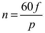
where f is the frequency of the input side, and p is the number of pole pairs of the input-side permanent magnet 4 and the input-side stator winding 3.
The input side and the output side share one rotor iron core 7, the number of pole pairs of the permanent magnet 6 at the output side is Np, a rotating magnetic field with Np opposite poles is generated in an air gap at the output side under synchronous rotating speed, and N-frequency-doubled symmetrical three-phase alternating-current voltage can be induced in the stator winding 9 at the output side corresponding to the Np opposite poles of the stator winding 9 at the output side, so that the conversion of electric energy frequency from the input side to the output side is realized.
The invention converts the frequency of the three-phase alternating voltage source into N times and then outputs the frequency to the load from the output end, which is 3 times for the topological structure of figure 1, and the frequency conversion multiple can be changed by changing the number of pole pairs of the input side stator winding 3, the number of pole pairs of the input side permanent magnet 4, the number of pole pairs of the output side stator winding 9 and the number of pole pairs of the output side permanent magnet 6.
FIG. 2 is a working circuit diagram of the present invention, U A 、U B 、U C For the input side three-phase stator input voltage, phaseA in 、PhaseB in 、PhaseC in For the input-side stator three-phase winding, phaseA out 、 PhaseB out 、PhaseC out For the output side stator three-phase winding, Z load Is an outputThe load impedance of the terminal. Furthermore, in the permanent magnet motor, a permanent magnet and a slotted armature core interact to generate cogging torque harmonic waves, phase voltage has certain waveform distortion, and the function of filtering phase voltage harmonic waves is realized under the matching of a filter and a filter resistor in a circuit. The resistance of the filter resistor is selected to be far larger than the impedance of the filter branch circuit and far smaller than the resistance of the load resistor, so that the filtering effect is ensured and the amplitude of the output voltage is not reduced.
The invention is applied to a power system adopting frequency division transmission by utilizing finite element simulation software, a voltage transformation effect graph of the operation simulation of the invention is shown in figure 3, the voltage frequency of an input end is 50/3Hz, and the voltage frequency of an output end is 50Hz through a voltage transformation frequency converter, so that the triple frequency electric energy conversion is realized.
Finally, the invention adopts the magnetic isolation area 5 to separate the magnetic field, realizes the function of frequency conversion according to the principle that the number of pole pairs of the input side and the output side are different and the synchronous rotating speed is the same, can realize the conversion of the frequency and the voltage of an electric signal according to the actual requirement, and adopts the asynchronous starting method that the rotor core 7 is added with the starting cage 2 to start, thereby completely separating the independent work of the power electronic device; the input side and the output side share one rotor core 7, and the space utilization rate of the device is high. Furthermore, the invention is based on the design principle of the permanent magnet synchronous motor, has mature technology, high reliability in engineering, very low technical cost and better economy. Furthermore, the invention is applied to the power system, can alleviate the trend of high-power electronic equipment of a new generation power system, and improves the stability of the power system.
The above embodiments are only used for illustrating the technical solutions of the present invention and not for limiting the same, and after reading the present application, those skilled in the art will make various modifications or alterations of the present invention with reference to the above embodiments within the scope of the claims of the present patent application.
Claims (5)
1. A voltage converter designed based on a double-stator permanent magnet synchronous motor is characterized by comprising an input side stator core (1), a rotor core (7) and an output side stator core (8);
an input side stator core (1), a rotor core (7) and an output side stator core (8) are sequentially distributed from inside to outside, wherein an input side stator winding (3) is wound on the input side stator core (1), an output side stator winding (9) is wound on the inner wall of the output side stator core (8), the inner side of the rotor core (7) serves as the input side rotor core, and the outer side of the rotor core (7) serves as the output side rotor core, wherein a magnetic isolation area (5) is arranged between the input side rotor core and the output side rotor core, a starting cage (2) is arranged on the inner side of the input side rotor core, an input side permanent magnet (4) is arranged inside the input side rotor core, and an output side permanent magnet (6) is arranged on the outer wall of the output side rotor core;
three-phase windings of the input side stator winding (3) are arranged in p pairs;
under the condition that the original frequency is converted into N times of frequency, the three-phase winding of the output side stator winding (9) is arranged in an Np opposite pole mode;
the number of pole pairs of the input-side permanent magnet (4) and the output-side permanent magnet (6) is different, and under the condition that the original frequency is converted into N times of the frequency, the number of pole pairs of the output-side permanent magnet (6) is N times of the number of pole pairs of the input-side permanent magnet (4).
2. The voltage converter designed based on the double-stator permanent magnet synchronous motor as claimed in claim 1, wherein a three-phase filter circuit is connected to an output end of the voltage converter.
3. The variable voltage inverter based on the double-stator permanent magnet synchronous motor design according to claim 1, wherein the magnetism isolating area is made of a low-permeability material.
4. The variable-voltage frequency converter designed based on the double-stator permanent magnet synchronous motor as claimed in claim 1, wherein an air gap is formed between the rotor core (1) and the stator core (1) at the input side.
5. The variable voltage frequency converter designed based on the double-stator permanent magnet synchronous motor as claimed in claim 1, wherein an air gap is formed between the rotor core (1) and the output side stator core (8).
Priority Applications (1)
| Application Number | Priority Date | Filing Date | Title |
|---|---|---|---|
| CN202111396254.6A CN114123710B (en) | 2021-11-23 | 2021-11-23 | Variable-voltage frequency converter based on double-stator permanent magnet synchronous motor design |
Applications Claiming Priority (1)
| Application Number | Priority Date | Filing Date | Title |
|---|---|---|---|
| CN202111396254.6A CN114123710B (en) | 2021-11-23 | 2021-11-23 | Variable-voltage frequency converter based on double-stator permanent magnet synchronous motor design |
Publications (2)
| Publication Number | Publication Date |
|---|---|
| CN114123710A CN114123710A (en) | 2022-03-01 |
| CN114123710B true CN114123710B (en) | 2022-12-20 |
Family
ID=80440124
Family Applications (1)
| Application Number | Title | Priority Date | Filing Date |
|---|---|---|---|
| CN202111396254.6A Active CN114123710B (en) | 2021-11-23 | 2021-11-23 | Variable-voltage frequency converter based on double-stator permanent magnet synchronous motor design |
Country Status (1)
| Country | Link |
|---|---|
| CN (1) | CN114123710B (en) |
Families Citing this family (1)
| Publication number | Priority date | Publication date | Assignee | Title |
|---|---|---|---|---|
| CN114614644A (en) * | 2022-03-24 | 2022-06-10 | 西安交通大学 | Rotary triple-frequency electric energy conversion device and working method thereof |
Citations (4)
| Publication number | Priority date | Publication date | Assignee | Title |
|---|---|---|---|---|
| CN202978667U (en) * | 2012-12-13 | 2013-06-05 | 中国矿业大学 | Variable-frequency transformer |
| CN106026583A (en) * | 2016-05-30 | 2016-10-12 | 东南大学 | Magnetic field modulation-based double-stator hybrid excitation motor |
| CN111509938A (en) * | 2020-03-24 | 2020-08-07 | 江苏大学 | Multi-working-mode double-stator magnetic field modulation motor |
| CN211377853U (en) * | 2019-11-08 | 2020-08-28 | 国家能源集团谏壁发电厂 | Winding type permanent magnet coupling speed regulating motor |
Family Cites Families (1)
| Publication number | Priority date | Publication date | Assignee | Title |
|---|---|---|---|---|
| GB2488129A (en) * | 2011-02-16 | 2012-08-22 | Rolls Royce Plc | Modulated field electromagnetic machine |
-
2021
- 2021-11-23 CN CN202111396254.6A patent/CN114123710B/en active Active
Patent Citations (4)
| Publication number | Priority date | Publication date | Assignee | Title |
|---|---|---|---|---|
| CN202978667U (en) * | 2012-12-13 | 2013-06-05 | 中国矿业大学 | Variable-frequency transformer |
| CN106026583A (en) * | 2016-05-30 | 2016-10-12 | 东南大学 | Magnetic field modulation-based double-stator hybrid excitation motor |
| CN211377853U (en) * | 2019-11-08 | 2020-08-28 | 国家能源集团谏壁发电厂 | Winding type permanent magnet coupling speed regulating motor |
| CN111509938A (en) * | 2020-03-24 | 2020-08-07 | 江苏大学 | Multi-working-mode double-stator magnetic field modulation motor |
Also Published As
| Publication number | Publication date |
|---|---|
| CN114123710A (en) | 2022-03-01 |
Similar Documents
| Publication | Publication Date | Title |
|---|---|---|
| CN106711992B (en) | Topological structure of permanent magnet direct current fan cluster system | |
| CN109286258B (en) | Preparation method of wound rotor winding of alternating-current brushless double-fed motor | |
| CN114123710B (en) | Variable-voltage frequency converter based on double-stator permanent magnet synchronous motor design | |
| CN106253530B (en) | One kind is across two tooth concentratred winding vernier magnetoes | |
| CN107994816A (en) | A kind of electric system and its optimal control method | |
| CN102568799B (en) | Phase-shift transformer and electric energy transmission device with same | |
| CN114123711B (en) | Surface-mounted permanent magnet variable voltage frequency converter based on magnetic field modulation principle and design method | |
| CN209896881U (en) | Double-stator AC/DC generator motor | |
| CN114123712B (en) | Voltage converter based on double-stator electric excitation synchronous motor design | |
| Pan et al. | Design of a Wound Rotor Brushless Doubly-Fed Machine With 1/5 Pole-Pair Combination | |
| CN114050705B (en) | Electric excitation variable voltage frequency converter based on magnetic field modulation principle and design method | |
| CN114050704B (en) | Built-in permanent magnet variable voltage frequency converter based on magnetic field modulation principle and design method | |
| CN209896880U (en) | Double-stator alternating current-direct current generating motor system applied to energy storage power station | |
| CN112821736A (en) | Method, system and medium for suppressing harmonic waves of machine side converter of disc type counter-rotating permanent magnet hydroelectric generator | |
| CN202150822U (en) | Four-quadrant frequency-converter main circuit used for constant-power wide range speed control of permanent magnet synchronous motor | |
| CN206099573U (en) | A. C. brushless double -fed motor | |
| CN114915185A (en) | Permanent magnet variable voltage frequency converter based on double-stator axial flux motor design | |
| CN115250049A (en) | Electric excitation voltage converter based on double-stator axial flux motor design | |
| Baziruwiha et al. | Triple Three-Phase High Pole Number Non-Overlap Winding Reluctance Synchronous Wind Generator | |
| CN114977835A (en) | Axial magnetic flux electric excitation voltage converter based on magnetic field modulation principle | |
| CN114944765A (en) | Axial magnetic flux permanent magnet variable voltage frequency converter based on magnetic field modulation principle | |
| CN112600383B (en) | Double-fed linear motor structure with long stator hollow winding and double sides | |
| Pan et al. | Design of a 1/3 pole-pair combination brushless doubly-fed machine with a two-phase rotor winding | |
| CN116436252A (en) | Electric excitation rotary electric energy conversion device, working method thereof and power grid structure | |
| WO2021120431A1 (en) | High-speed vernier motor having independently-driven conductor and compact structure |
Legal Events
| Date | Code | Title | Description |
|---|---|---|---|
| PB01 | Publication | ||
| PB01 | Publication | ||
| SE01 | Entry into force of request for substantive examination | ||
| SE01 | Entry into force of request for substantive examination | ||
| GR01 | Patent grant | ||
| GR01 | Patent grant |