Disclosure of Invention
In view of the above, it is necessary to provide a shape detection apparatus for detecting the structure of an annular workpiece with high efficiency and accuracy.
A shape detection apparatus for detecting a shape of an annular workpiece, characterized by comprising:
the first detection assembly comprises a plurality of cameras, the cameras are used for acquiring the shape images of the annular workpiece when the annular workpiece is at the first detection station, the cameras are arranged around the first detection station at intervals, and the optical axis of at least one camera in the cameras faces to the inner wall of the annular workpiece.
In one embodiment, the shape detection apparatus further includes a processor electrically connected to the plurality of cameras for processing images acquired by the plurality of cameras.
In one embodiment, the shape detection apparatus further includes a moving mechanism, the annular workpiece is mounted on the moving mechanism, and the moving mechanism is configured to drive the annular workpiece to move to the first detection station.
In one embodiment, the first detection assembly further comprises a bearing member, the moving mechanism comprises a turntable, a through hole is formed in the rotation center of the turntable, the bearing member is arranged in the through hole in a penetrating manner, and a gap is formed between the bearing member and the hole wall of the through hole; at least one camera is arranged on the bearing piece.
In one embodiment, the plurality of cameras include a first camera, an inner wall of the annular workpiece is surrounded to form an inner ring channel, an extending direction of an optical axis of the first camera is parallel to an extending direction of the inner ring channel, and the optical axis of the first camera is collinear with a center line of revolution of the inner ring channel.
In one embodiment, the plurality of cameras comprises a second camera, a third camera, a fourth camera and a fifth camera which are evenly distributed at intervals, and the second camera, the third camera, the fourth camera and the fifth camera are all focused on the first detection station.
In one embodiment, the first inspection assembly further comprises a first light source facing the first inspection station.
In one embodiment, the first detection assembly further includes a plurality of first adjustment structures, the number of the first adjustment structures corresponds to the number of the cameras, and the plurality of cameras are disposed on the plurality of first adjustment structures in a one-to-one correspondence.
In one embodiment, the first adjusting structure includes a first adjusting device, the first adjusting device includes a first slide rail and a first sliding table slidably engaged with the first slide rail, the camera is disposed on the first sliding table, and the first sliding table is capable of adjusting a distance between the camera and the first detection station when moving relative to the first slide rail.
In one embodiment, the first adjusting structure further comprises a first control device, the first control device comprises a mounting plate, the camera is arranged on the mounting plate, the mounting plate is rotatably connected with the first sliding table, and when the mounting plate rotates relative to the first sliding table, the optical axis of the camera can face the annular workpiece.
In one embodiment, the first control device further comprises a mark piece, one side of the mark piece is connected with the first sliding table, the other side of the mark piece is connected with the mounting plate in a rotating mode, a first mark is arranged on the mark piece, a second mark corresponding to the first mark is arranged on the mounting plate, and the second mark and the first mark are matched to determine the position of the mounting plate relative to the mark piece.
In one embodiment, the shape inspection apparatus further comprises a second inspection assembly for inspecting the inner diameter of the annular workpiece while the annular workpiece is at the second inspection station.
In one embodiment, the second detection assembly comprises a second adjusting device and a scanning member, the second adjusting device is connected with the scanning member and used for driving the scanning member to move, and the scanning member is used for scanning the inner diameter of the annular workpiece.
In one embodiment, the second adjusting device comprises a linear scanning driving part, a second sliding rail and a second sliding table in sliding fit with the second sliding rail, the scanning part is connected with the second sliding table, the scanning part comprises a linear scanning first station and a linear scanning second station, and the linear scanning driving part can drive the scanning part to move along with the second sliding table relative to the second sliding rail between the linear scanning first station and the linear scanning second station.
In one embodiment, the scanning piece at the first linear scanning station has a first projection on a plane where the moving mechanism is located; the scanning piece positioned at the second linear scanning station is provided with a second projection on the plane where the moving mechanism is positioned, and the first projection and the second projection are respectively positioned at two sides of the second detection station.
In one embodiment, the shape detection apparatus further comprises a third detection assembly for acquiring an image of the shape of the annular workpiece when the annular workpiece is at a third detection station.
In one embodiment, the third detection assembly comprises an endoscope, an inner ring channel is formed by enclosing the inner wall of the annular workpiece, the extension direction of the optical axis of the endoscope is the same as that of the inner ring channel, and the optical axis of the endoscope passes through the revolution center of the inner ring channel.
In one embodiment, the third detection assembly further includes a third adjustment device, the third adjustment device includes a third slide rail and a third slide table slidably engaged with the third slide rail, the endoscope is disposed on the third slide table, and the distance between the endoscope and the third detection station can be adjusted when the third slide table moves relative to the third slide rail.
In one embodiment, when the annular workpiece is at the third inspection station, the distance between one end of the endoscope close to the third inspection station and the annular workpiece is not more than 100 mm.
In one embodiment, the third inspection assembly further comprises a second light source, said second light source facing said third inspection station.
In one embodiment, the moving mechanism is provided with a plurality of fixed jigs uniformly distributed at intervals, the fixed jigs are provided with accommodating grooves matched with the shapes of the annular workpieces, and the annular workpieces are arranged in the accommodating grooves.
A shape inspection method for inspecting a shape of an annular workpiece, the shape inspection method comprising a camera inspection step including:
s11: moving the annular workpiece to a first detection station;
s12: controlling a plurality of cameras to shoot images of different positions of the annular workpiece;
s13: transmitting images taken by a plurality of the cameras to a processor;
s14: the processor integrates the images shot by the cameras and analyzes whether the structure of the annular workpiece in the integrated images is qualified or not. In one embodiment, the from content
In one embodiment, step S20 is further included after step S14: and when the image shot by the first detection assembly is unclear, the annular workpiece is moved to a third detection station for endoscope detection.
In one embodiment, the step of endoscopically detecting comprises:
s21: moving the annular workpiece to a third inspection station;
s22: the endoscope shoots the whole structure of the annular workpiece;
s23: transmitting a photographing result of the endoscope to the processor;
s24: the processor analyzes whether the structure of the annular workpiece in the endoscope shot image is qualified.
In one embodiment, the outline detection method further includes a line scan detection step:
s31: moving the annular workpiece to a second detection station;
s32: the scanning piece scans the inner diameter of the annular workpiece;
s33: transmitting the scanning result of the scanning piece to the processor;
s34: the processor analyzes the scanning result and judges whether the inner diameter of the annular workpiece is qualified.
In one embodiment, in the step S32, the annular workpiece stops moving for 1 to 5 seconds, and the scanning component linearly scans the annular workpiece at a constant speed.
According to the appearance detection equipment, the plurality of cameras are arranged around the first detection station at intervals, and are used for acquiring the appearance image of the annular workpiece when the annular workpiece is located at the first detection station. In this way, the outer shape of the annular workpiece can be detected comprehensively by the cooperation of the plurality of cameras. Compared with manual detection, the efficiency can be improved, and the detection accuracy can also be improved. And the optical axis of at least one camera in the plurality of cameras faces to the inner wall of the annular workpiece, so that the cameras can identify characters on the inner wall of the annular workpiece and detect whether the characters on the inner wall of the annular workpiece have defects. Therefore, the accuracy of detecting the characters on the inner wall of the annular workpiece is greatly improved.
Detailed Description
In order to make the aforementioned objects, features and advantages of the present invention comprehensible, embodiments accompanied with figures are described in detail below. In the following description, numerous specific details are set forth in order to provide a thorough understanding of the present invention. This invention may, however, be embodied in many different forms and should not be construed as limited to the embodiments set forth herein.
In the description of the present invention, it is to be understood that the terms "central," "longitudinal," "lateral," "length," "width," "thickness," "upper," "lower," "front," "rear," "left," "right," "vertical," "horizontal," "top," "bottom," "inner," "outer," "clockwise," "counterclockwise," "axial," "radial," "circumferential," and the like are used in the orientations and positional relationships indicated in the drawings for convenience in describing the invention and to simplify the description, and are not intended to indicate or imply that the referenced device or element must have a particular orientation, be constructed and operated in a particular orientation, and are not to be considered limiting of the invention.
Furthermore, the terms "first", "second" and "first" are used for descriptive purposes only and are not to be construed as indicating or implying relative importance or implicitly indicating the number of technical features indicated. Thus, a feature defined as "first" or "second" may explicitly or implicitly include at least one such feature. In the description of the present invention, "a plurality" means at least two, e.g., two, three, etc., unless explicitly specified otherwise.
In the present invention, unless otherwise expressly stated or limited, the terms "mounted," "connected," "secured," and the like are to be construed broadly and can, for example, be fixedly connected, detachably connected, or integrally formed; can be mechanically or electrically connected; they may be directly connected or indirectly connected through intervening media, or they may be interconnected within two elements or in a relationship where two elements interact with each other unless otherwise specifically limited. The specific meanings of the above terms in the present invention can be understood by those skilled in the art according to specific situations.
In the present invention, unless otherwise expressly stated or limited, the first feature "on" or "under" the second feature may be directly contacting the first and second features or indirectly contacting the first and second features through an intermediate. Also, a first feature "on," "over," and "above" a second feature may be directly or diagonally above the second feature, or may simply indicate that the first feature is at a higher level than the second feature. A first feature being "under," "below," and "beneath" a second feature may be directly under or obliquely under the first feature, or may simply mean that the first feature is at a lesser elevation than the second feature.
It will be understood that when an element is referred to as being "secured to" or "disposed on" another element, it can be directly on the other element or intervening elements may also be present. When an element is referred to as being "connected" to another element, it can be directly connected to the other element or intervening elements may also be present. The terms "vertical," "horizontal," "upper," "lower," "left," "right," and the like as used herein are for illustrative purposes only and do not denote a unique embodiment.
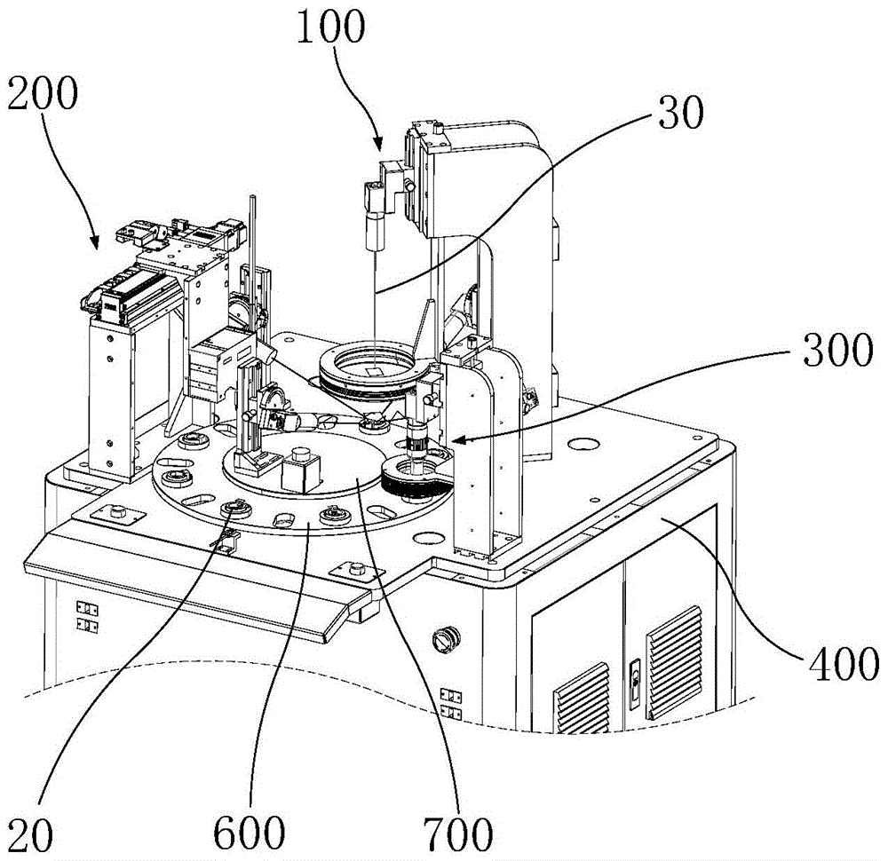
Referring to fig. 1, fig. 1 is a schematic axial view of a shape detection apparatus according to an embodiment of the present invention, fig. 2 is a schematic axial view of a partial structure of the shape detection apparatus shown in fig. 1, and fig. 3 is a schematic axial view of a first detection assembly and a moving mechanism in the shape detection apparatus shown in fig. 2.
Referring to fig. 1, a profile inspecting apparatus 10 for inspecting a profile of an annular workpiece 20 is provided according to an embodiment of the present invention. The appearance inspection apparatus 10 includes an upper case 500, a lower case 400, and a first inspection unit 100. The upper housing 500 is connected to the lower housing 400, and the upper housing 500 and the lower housing 400 together enclose a detection space 510. The first detecting element 100 is disposed on a side of the lower casing 400 close to the upper casing 500, that is, the first detecting element 100 is located in the detecting space 510. In this way, the detection process of the first detection assembly 100 can be located in a relatively closed detection space 510, so as to avoid the influence of the change of the external environment on the detection result as much as possible.
Referring to fig. 1-3 in conjunction with fig. 4, in one embodiment, the first detecting element 100 includes a plurality of cameras. A plurality of cameras for acquiring an outline image of the annular workpiece 20 while the annular workpiece 20 is at the first inspection station 180; a plurality of cameras are spaced around the first inspection station 180 with the optical axis 30 of at least one of the plurality of cameras facing the inner wall 21 of the annular workpiece 20. Referring to FIG. 3, the first inspection station 180 is positioned as shown in FIG. 3. It will be understood that the optical axis 30 of the camera refers to a line along which a degree of rotational symmetry is present in an optical system such as a camera lens or microscope. The optical axis 30 is not a true line, and the optical axis 30 is a dashed line that defines the path of light traveling through the system. That is, the optical axis 30 described in the embodiments and shown in the drawings is a schematic view, and there is actually no axis. The optical axis 30 is a well known concept in the prior art and will not be described in detail. It should be understood that the description of the optical axis 30 in the embodiments is only used to describe the corresponding relationship between the shooting directions of the plurality of cameras or the corresponding detection assemblies and the annular workpiece 20 or the corresponding detection stations, and the shooting range of the cameras is not limited to the direction indicated by the optical axis 30. In other words, in the direction opposite to the camera, the camera can shoot the outline image of the annular workpiece 20 in a certain area, and the shooting area of the camera can be adjusted by different annular workpieces 20 to meet the requirement of shooting the image by the camera, so that the description is omitted.
In the above-described outline inspecting apparatus 10, a plurality of cameras are disposed at intervals around the first inspection station 180, and the plurality of cameras are used to acquire the outline image of the annular workpiece 20 when the annular workpiece 20 is at the first inspection station 180. In this way, the outer shape of the ring-shaped workpiece 20 can be detected over the entire surface by the cooperation of the plurality of cameras. Compared with the manual detection, the efficiency can be improved, and the detection accuracy can also be improved. And the optical axis 30 of at least one camera in the plurality of cameras is opposite to the inner wall 21 of the annular workpiece 20, so that the cameras can identify the characters 22 on the inner wall 21 of the annular workpiece 20 and can detect whether the characters 22 on the inner wall 21 of the annular workpiece 20 have defects or not. Thus, the accuracy of detecting the characters 22 on the inner wall 21 of the annular workpiece 20 is greatly improved.
In one embodiment, the form detection apparatus 10 further includes a processor (not shown, the same applies below). The processor is electrically connected with the cameras and used for processing images acquired by the cameras. In other words, the plurality of cameras acquire the outline image of the annular workpiece 20 at the first inspection station 180 and then send the image to the processor for processing. The processor analyzes and identifies the structure of the annular workpiece 20 and the structure of the characters 22 on the annular workpiece 20. Whether the annular workpiece 20 has defects is judged through the analysis result of the processor, namely whether the annular workpiece 20 is qualified.
Referring to fig. 2 and 3, in one embodiment, the shape inspection apparatus 10 further includes a moving mechanism 600, and the annular workpiece 20 is mounted on the moving mechanism 600. The moving mechanism 600 is used for driving the annular workpiece 20 to move to the first detection station 180. Specifically, the moving mechanism 600 is disposed on the lower housing 400, and the annular workpiece 20 can be automatically moved to the first inspection station 180 by the driving action of the moving mechanism 600 to be inspected by the first inspection assembly 100, so that the inspection efficiency of the outer shape inspection apparatus 10 can be improved.
With continued reference to fig. 2 and 3, in one embodiment, the first detecting assembly 100 further includes a supporting member 700. The moving mechanism 600 includes a rotating plate 610, and a through hole (not shown, the same applies below) is formed at a rotation center of the rotating plate 610. The supporting member 700 is disposed through the through hole, and there is a gap between the supporting member 700 and the hole wall of the through hole. At least one camera is provided on the carrier 700. In this embodiment, the turntable 610 is rotatably coupled to the lower housing 400. The carrier 700 is coupled with the lower case 400 to carry the camera. There is a space between the carrier 700 and the hole wall of the through hole, so that the carrier 700 can be prevented from obstructing the movement of the rotary table 610, and the rotary table 610 is convenient for moving the annular workpiece 20 to the first detection station 180. It will be appreciated that the annular workpiece 20 needs to be moved by the turntable 610 to the first inspection station 180, and it is clear that providing a camera at the location of the turntable 610 will result in interference with the transport function of the turntable 610. If a camera is not arranged on one side of the first detection station 180 close to the rotary table 610, the annular workpiece 20 at the first detection station 180 is difficult to detect completely, and a blind area exists in detection.
In the above embodiment, the turntable 610 is provided with a through hole, and the bearing member 700 for bearing the camera is arranged in the through hole. With this arrangement, the mounting position of the camera can be prevented from obstructing the rotational movement of the dial 610. That is, the installation positions of the cameras can be flexibly set, so that the plurality of cameras can comprehensively acquire the appearance image of the annular workpiece 20 from different angles, and the occurrence of a detection blind area is avoided. So set up, can guarantee the comprehensiveness that detects, improve the accuracy of testing result.
Referring to fig. 3 and 4, in one embodiment, the plurality of cameras includes a first camera 110. The inner wall 21 of the annular workpiece 20 encloses an inner ring channel 23. The extending direction of the optical axis 30 of the first camera 110 is parallel to the extending direction of the inner ring channel 23, and the optical axis 30 of the first camera 110 is collinear with the center line of gyration of the inner ring channel 23. The optical axis 30 of the first camera 110 is shown in fig. 3; the inner ring channel 23 is shown in fig. 4, and the extending direction of the inner ring channel 23 and the rotation center line of the inner ring channel 23 refer to reference sign K in fig. 4.
It is understood that, in other embodiments, if the inner wall 21 of the annular workpiece 20 has a relatively complex structure or the shape of the character 22 is relatively complex, the plurality of cameras may also include a plurality of cameras that function the same as the first camera 110. In the following, two first cameras 110 are taken as an example, that is, in the present embodiment, two first cameras 110 may be provided. The extending direction of the optical axes 30 of the two first cameras 110 and the extending direction of the inner ring channel 23 form an angle of 0-90 degrees, and the optical axes 30 of the two cameras are opposite to the inner wall 21 of the annular workpiece 20. In this way, the accuracy of detecting the inner circle character 22 of the annular workpiece 20 can be improved by the cooperation of the two first cameras 110.
In the above embodiment, referring to fig. 3 and 4, the extending direction of the optical axis 30 of the first camera 110 is the same as the extending direction of the inner ring channel 23, and the optical axis 30 of the first camera 110 is collinear with the revolution center line of the inner wall 21 of the annular workpiece 20. In this way, the inner wall 21 of the annular workpiece 20 can be covered only by the first camera 110, that is, the characters 22 on the inner wall 21 of the annular workpiece 20 can be recognized by the first camera 110, so that whether the characters 22 on the inner wall 21 of the annular workpiece 20 have defects can be efficiently detected.
Referring to fig. 3, 4 and 5, in one embodiment, the plurality of cameras include a second camera 120, a third camera 130, a fourth camera 140 and a fifth camera 150 which are uniformly distributed at intervals. The second camera 120, the third camera 130, the fourth camera 140, and the fifth camera 150 are all focused on the first inspection station 180. The second camera 120, the third camera 130, the fourth camera 140 and the fifth camera 150 are focused on the first detection station 180, that is, before the shape detection device 10 detects the annular workpiece 20, parameters such as the position, the focal length and the shooting angle of each camera can be adjusted according to the shapes of different annular workpieces 20, so that when the annular workpiece 20 is located at the first detection station 180, the cameras can all obtain clear images.
Specifically, in the above embodiment, the distances between the second camera 120, the third camera 130, the fourth camera 140, and the fifth camera 150 are all 90 °, and by providing a plurality of second cameras 120, third cameras 130, fourth cameras 140, and fifth cameras 150 distributed at intervals of 90 °, the overall shape of the annular workpiece 20 can be detected from four directions in which the distribution is uniform. Moreover, the intervals among the second camera 120, the third camera 130, the fourth camera 140 and the fifth camera 150 are all 90 °, so that the shooting ranges of the four cameras can completely cover the appearance of the annular workpiece 20, and a detection blind area is avoided.
It is understood that the plurality of cameras may further include three cameras or five cameras, etc. which are uniformly spaced, and the specific number of cameras in the plurality of cameras may be appropriately adjusted according to the relevant factors of the size of the ring-shaped workpiece 20, the size of the turntable 610, and the size of the carrier 700, and the spacing between the plurality of cameras may be adaptively adjusted. Specifically, for example, three cameras may be set to have an interval of 120 ° and five cameras may be set to have an interval of 72 °. Meanwhile, it is understood that the intervals between the plurality of cameras may be non-uniform according to the structure of the turntable 610 and the structure of the carrier 700. It is necessary to allow the shooting ranges of the plurality of cameras to cover all over the respective areas on the annular workpiece 20 at this time to avoid the occurrence of detection blind areas.
Referring to fig. 3, in one embodiment, the first inspection assembly 100 further includes a first light source 170, the first light source 170 facing the first inspection station 180. The first light source 170 can illuminate the first inspection station 180. Therefore, the influence of the change of the light and the brightness of the external environment on the shooting effect can be reduced. Meanwhile, the first light source 170 can also be used for illuminating some detailed structures on the annular workpiece 20, and specifically, for example, can illuminate the characters 22 on the annular workpiece 20 to determine whether the structures of the characters 22 are clear and complete. Or a gap defect, a scratch, etc., which may exist on the ring-shaped workpiece 20. The first light source 170 may be disposed on the first slide rail 1611 corresponding to the upper housing 500, the lower housing 400 or the first camera 110.
Referring to fig. 6 in combination with fig. 3, in an embodiment, the first detecting assembly 100 further includes a plurality of first adjusting structures 160, the number of the first adjusting structures 160 corresponds to the number of the cameras, and the plurality of cameras are disposed on the plurality of first adjusting structures 160 in a one-to-one correspondence. The position of the camera can be adjusted through the first adjusting structure 160, on one hand, the position aligned with the optical axis 30 of the camera can be corrected, and on the other hand, the matching of a plurality of cameras can detect the annular workpieces 20 with different sizes by adjusting the first adjusting structure 160 corresponding to each camera, so that the applicability of the appearance detection equipment 10 is improved.
Referring again to fig. 6 in conjunction with fig. 3, in one embodiment, the first adjustment structure 160 includes a first adjustment device 161. The first adjusting device 161 includes a first slide rail 1611 and a first sliding table 1612 slidably engaged with the first slide rail 1611. The camera is arranged on the first sliding table 1612. When the first sliding table 1612 moves relative to the first sliding rail 1611, the distance between the camera and the first detection station 180 can be adjusted. Through setting up first adjusting device 161, can adjust the distance between camera and the first detection station 180, so can make first detection subassembly 100 adapt to the annular work piece 20 of different sizes, also can avoid other structures on appearance check out test set 10 simultaneously, for example carousel 610 or the first structure 160 etc. of adjusting that other cameras correspond, block optical axis 30 and lead to unable clear or complete annular work piece 20's outward appearance image of obtaining. The distance between the camera and the first inspection station 180 is referred to as a Z-axis distance in fig. 3 and 6.
Specifically, one end of the first slide rail 1611 is connected with the lower housing 400 to keep the first adjusting device 161 relatively stable. The first adjusting device 161 further includes a first adjusting handle 1612a and a first clamping member, and the first adjusting handle 1612a is connected with the first sliding table 1612. The first clamping piece is arranged on the first sliding table 1612 and used for fixing the first sliding table 1612 relative to the first sliding rail 1611. The first sliding table 1612 can be controlled to slide relative to the first sliding rail 1611 by the first adjusting handle 1612a, so as to adjust the position of the camera arranged on the first sliding table 1612; can avoid first slip table 1612 to remove relative first slide rail 1611 through first clamping piece to prevent that the camera from taking place to rock, influencing the result of shooing.
Referring to fig. 6, in one embodiment, the first adjusting structure 160 further includes a first control device 162. The first control device 162 includes a mounting plate 1621. The camera is mounted on the mounting plate 1621. The mounting plate 1621 is rotatably connected to the first slide table 1612, and the optical axis 30 of the camera can be made to face the annular workpiece 20 when the mounting plate 1621 rotates relative to the first slide table 1612. Specifically, in combination with the above-mentioned embodiment, the first adjusting device 161 adjusts the distance between the camera and the first detection station 180, and the first control device 162 adjusts the optical axis 30 of the camera, so that the camera can photograph the outer shape of the annular workpiece 20 at a proper position, that is, the optical axis 30 is prevented from being blocked or partially blocked and being unable to photograph the annular workpiece 20. In other words, by cooperation of the first adjusting device 161 and the first control device 162, the camera can be caused to take an image of the ring-shaped workpiece 20 at an appropriate angle.
It can be understood that each camera is provided with a corresponding first adjusting structure 160, and the corresponding first adjusting structure 160 of each camera includes a first adjusting device 161 and a first control device 162. In this way, by adaptive adjustment among the first adjusting structures 160, the plurality of cameras can cover the annular workpiece 20 to comprehensively acquire the outer shape structure of the annular workpiece 20, so as to comprehensively detect the outer shape structure of the annular workpiece 20.
That is, specifically, the distance between the camera adjusted by the first adjusting device 161 corresponding to each camera and the first detection station 180 may be the same or different. In other words, the Z-axis coordinate value corresponding to each camera may be the same or different, and the optical axis 30 of the cameras with different Z-axis coordinate values may have different included angles with the extending direction of the inner ring channel 23. That is, the positions of the cameras may be adjusted by the first adjusting structure 160 so that each camera can simultaneously photograph the inner wall 21 and the outer wall of the ring-shaped workpiece 20. In other words, the adjustment of the first adjustment structure 160 corresponding to the plurality of cameras enables the plurality of cameras to capture the characters 22 on the inner wall 21. In this way, the accuracy of detection of the characters 22 on the inner wall 21 of the annular workpiece 20 is even further improved.
Further, in conjunction with the above-described embodiments, the first camera 110 may be free of the first control device 162. It is understood that the extending direction and the center line of revolution of the inner ring passage 23 of the annular workpiece 20 of different sizes are the same or almost the same for the annular workpiece 20. Since the proper shooting angle of the first camera 110 is: the extending direction of the optical axis 30 of the first camera 110 is parallel to the extending direction of the inner ring channel 23, and the optical axis 30 of the first camera 110 is collinear with the center line of gyration of the inner ring channel 23. Therefore, only the annular workpiece 20 needs to be located at the first inspection station 180, so that the first camera 110 can be ensured to have a proper shooting angle. It should be understood that when there are two or more first cameras 110, the corresponding first adjusting structures 160 of the first cameras 110 still need the first control device 162 to adjust the shooting angles.
With continued reference to fig. 6, in one embodiment, the first control device 162 further includes a marker 1622. One side of the flag 1622 is connected to the first slide table 1612. The other side of the marking piece 1622 is rotatably connected with the mounting plate 1621, and a first mark 1622a is arranged on the marking piece 1622. The mounting plate 1621 is provided with a second mark 1621b corresponding to the first mark 1622a, and the second mark 1621b is matched with the first mark 1622a to determine the position of the mounting plate 1621 relative to the mark 1622.
In the above embodiment, the angle of rotation of the mounting plate 1621 relative to the marker 1622 can be known by the cooperation between the first marker 1622a provided on the marker 1622 and the second marker 1621b provided on the mounting plate 1621. In this way, the first adjusting device 161 and the first control device 162 do not need to be repeatedly adjusted for the annular workpiece 20 with the same external shape or the annular workpiece 20 with the similar external shape, and the position parameters obtained in the first adjustment can be recorded to directly use the parameters. That is, by providing the first mark 1622a and the second mark 1621b coupled to the first mark 1622a, the position of the camera can be easily adjusted. This can improve the efficiency of detection.
It is understood that the first mark 1622a may also be directly disposed on the first sliding table 1612. One of the first mark 1622a and the second mark 1621b is a pointer, and the other is a scale. Specifically, for example, the first mark 1622a may be a pointer and the second mark 1621b may be a scale. During rotation of the camera, i.e., at any position of the mounting plate 1621 relative to the flag 1622, the pointer of the first flag 1622a may indicate a scale of the second flag 1621b corresponding to the position of the mounting plate 1621. Thus, repeated adjustment is facilitated. Similarly, a first mark 1622a and a second mark 1621b may be provided for the first adjustment device 161 to determine the relative position of the first sliding table 1612 and the first sliding rail 1611.
Referring to fig. 7 in conjunction with fig. 4, in one embodiment, the shape inspection apparatus 10 further includes a second inspection assembly 200. The second inspection assembly 200 is used to inspect the inner diameter of the annular workpiece 20 while the annular workpiece 20 is at the second inspection station 210. It will be appreciated that the annular workpiece 20 is movable with the turntable 610 between the first inspection station 180 and the second inspection station 210. In this manner, the inner diameter of the annular workpiece 20 can be conveniently detected by the second detection station 210. The method avoids inaccurate side amount of the parameters when the specific parameters are detected by the camera.
With continued reference to fig. 7, in one embodiment, the second detecting assembly 200 includes a second adjusting device 220 and a scanning element 230, the second adjusting device 220 is connected to the scanning element 230 for driving the scanning element 230 to move, and the scanning element 230 is used for scanning the inner diameter of the annular workpiece 20. Specifically, the second inspection assembly 200 can acquire the inner diameter of the annular workpiece 20 by way of linear scanning. The inner diameter of the annular workpiece 20 is acquired by linear scanning, and relative movement between the second inspection assembly 200 and the annular workpiece 20 is required. Compared with the method that the scanning element 230 is kept fixed and the annular workpiece 20 moves, the movement speed of the scanning element 230 can be better controlled by driving the scanning element 230 to move through the second adjusting device 220, so that the scanning result is more accurate, and the detection accuracy is improved. Of course, the scanning component 230 may be fixed according to the requirement, and the annular workpiece 20 may move relative to the scanning component 230 during the linear scanning process, which is not limited herein.
Referring to fig. 7 again in conjunction with fig. 5, in an embodiment, the second adjusting device 220 includes a linear scanning driving element 221, a second sliding rail 222, and a second sliding table 223 slidably engaged with the second sliding rail 222. The scanning unit 230 is connected to the second sliding table 223, and the scanning unit 230 includes a first linear scanning station 250 and a second linear scanning station 260. The linear scanning driving member 221 can drive the scanning member 230 to move between the first linear scanning station 250 and the second linear scanning station 260 along with the second sliding table 223 relative to the second sliding rail 222. Specifically, the extending direction of the second sliding rail 222 may be a tangential direction of the rotating disc 610. When the second slide table 223 moves, the shortest distance between the second slide table 223 and the moving mechanism 600 is not changed. That is, the moving track of the second slide table 223 moving between the line scan first station 250 and the line scan second station 260 is parallel to the turntable 610. Thus, errors of scanning results caused by changes of scanning distances during the moving scanning process of the scanning element 230 can be avoided. Therefore, the accuracy of the detection result can be further ensured. It is understood that the second slide table 223 and the scanning member 230 shown in fig. 5 are in the line scanning first station 250. It should be understood that the first inspection station 180 and the second inspection station 210 in each embodiment are both positioned with the annular workpiece 20 in the moving mechanism 600 relative to each inspection assembly. The first linear scanning station 250 and the second linear scanning station 260 are two stations of the scanning element 230 or the scanning element 230 and the second sliding table 223 relative to the second sliding rail 222.
In one embodiment, the second adjustment device 220 includes a fixing frame 240. The second slide rail 222 is disposed on the fixing frame 240, and the second slide rail 222 is connected to the fixing frame 240. The fixing frame 240 is used for supporting the second slide rail 222, and the second sliding table 223 and the scanning element 230 disposed on the second slide rail 222. One end of the fixing frame 240 is coupled to the lower housing 400.
Referring to fig. 7 in conjunction with fig. 5, the scanning element 230 at the first linear scanning station 250 has a first projection on the plane of the moving mechanism 600; the scan element 230 at the second station 260 has a second projection onto the plane of the translation mechanism 600. The first projection and the second projection are respectively located at two sides of the second detection station 210. With the above embodiment, the second projections of the first projector are respectively located at two sides of the first detection station 180, and the scanning element 230 can move parallel to the moving mechanism 600. In this way, the scanning member 230 can scan and move from one side of the second inspection station 210 to the other side of the second inspection station 210 by the parallel moving mechanism 600. Therefore, the scanning piece 230 can be ensured to scan the whole appearance structure of the annular workpiece 20 comprehensively, and the accuracy of detecting the inner diameter is ensured. Thus, the reliability of the inner diameter detection of the second detection unit 200 can be improved.
Referring to fig. 8 in conjunction with fig. 4, in one embodiment, the shape inspection apparatus 10 further includes a third inspection assembly 300. The third inspection assembly 300 is used to acquire an image of the outline of the annular workpiece 20 while the annular workpiece 20 is at the third inspection station 310. In the present embodiment, it is understood that the third inspection assembly 300 has the same inspection function as the first inspection assembly 100, and the third inspection assembly 300 is used for inspecting the outline image of the annular workpiece 20, i.e. the third inspection assembly 300 is used for inspecting the shape of the inner wall 21 and the outer wall of the annular workpiece 20 and detecting whether structural defects exist. Meanwhile, the third detection assembly 300 can detect whether the characters 22 on the inner wall 21 of the annular workpiece 20 are defective or not.
In the above embodiment, when the result detected by the first detecting assembly 100 is not clear or the image has other defects, the moving mechanism 600 can move the annular workpiece 20 to the third detecting station 310. The third inspection assembly 300 is capable of further inspecting the configuration of the annular workpiece 20. It is understood that the third detecting member 300 is an auxiliary detecting member to the first detecting member 100, or the third detecting member 300 is a further accurate detecting member to the first detecting member 100. Of course, as mentioned above, the third detecting component 300 can completely detect each portion on the ring-shaped workpiece 20, and the above-mentioned auxiliary detection is only for easy understanding, and there is no limitation to the detection of the third detecting component 300.
Referring to fig. 8 in conjunction with fig. 4 and 5, in one embodiment, the third detection assembly 300 includes an endoscope 320. The inner wall 21 of the annular workpiece 20 is enclosed to form an inner ring channel 23. The direction of extension of the optical axis 30 of the endoscope 320 is the same as the direction of extension of the inner ring channel 23, and the optical axis 30 of the endoscope 320 passes through the center of revolution of the inner ring channel 23. Since the outer wall of the annular workpiece 20 mainly passes through the second camera 120, the third camera 130, the fourth camera 140 and the fifth camera 150, the problem of unclear detection is not easy to occur; however, the inner wall 21 of the annular workpiece 20 is mainly detected by the first camera 110, and the problem of unclear detection is relatively easy to occur. Moreover, the characters 22 are provided on the inner wall 21 of the annular workpiece 20, and the detection of the characters 22 requires higher detection accuracy than the detection of the outer wall of the annular workpiece 20. The optical axis 30 of the endoscope 320 is made to pass through the center of rotation of the inner ring channel 23 by setting the extending direction of the optical axis 30 of the endoscope 320 to be the same as the extending direction of the inner ring channel 23. In this way, it can be further ensured that the detection of the inner wall 21 of the annular workpiece 20 and the characters 22 on the inner wall 21 is more accurate. The detection effect of the shape detection apparatus 10 is ensured.
Referring to fig. 8, in one embodiment, the third detecting assembly 300 further includes a third adjusting device 330. The third adjusting device 330 includes a third slide rail 331 and a third slide table 332 slidably engaged with the third slide rail 331. The endoscope 320 is arranged on the third sliding table 332, and when the third sliding table 332 moves relative to the third sliding rail 331, the distance between the endoscope 320 and the third detection station 310 can be adjusted. In this way, the third detection assembly 300 can be adapted to different annular workpieces 20 by moving the third slide table 332 to adjust the position of the endoscope 320 for different annular workpieces 20. The third slide rail 331 is coupled to the lower housing 400 to relatively stabilize the position of the endoscope 320.
Specifically, the third adjusting device 330 includes a second adjusting handle 332a and a second clamping member 332b, and the second adjusting handle 332a is connected to the third sliding table 332. The second clamp 332b is provided on the third slide table 332, and the second clamp 332b is used to fix the third slide table 332 with respect to the third slide rail 331. The third sliding table 332 can be controlled to slide relative to the third sliding rail 331 through the second adjusting handle 332a, so as to adjust the position of the endoscope 320 arranged on the third sliding table 332; the third sliding table 332 can be prevented from moving relative to the third sliding rail 331 by the second clamping piece 332b, so that the endoscope 320 is prevented from shaking to influence the shooting result.
In one embodiment, when the annular workpiece 20 is at the third inspection station 310, the end of the endoscope 320 adjacent to the third inspection station 310 is no more than 100mm from the annular workpiece 20. Thus, the endoscope 320 can be ensured to shoot clear images, and the problem that the shot appearance images are unclear is avoided.
Referring to fig. 8, in one embodiment, the third inspection assembly 300 further includes a second light source 340, and the second light source 340 faces the third inspection station 310. Specifically, the second light source 340 may be directly disposed on the upper case 500, the lower case 400, or even on the third sliding table 332. The second light source 340 is used to provide a light source to the third inspection station 310 to illuminate the annular workpiece 20 located on the third inspection station 310. Therefore, the shooting effect of the endoscope 320 is prevented from being influenced by factors such as external light, and the detailed structures such as gaps and characters 22 on the annular workpiece 20 can be illuminated, so that the detection effect is improved.
In various embodiments, it is understood that the second detecting element 200 and the third detecting element 300 are also electrically connected to the processor. The second and third inspection assemblies 200 and 300 can transmit the results of the scanning or photographing to the processor. The processor can analyze and identify the detection results of the second detection assembly 200 and the third detection assembly 300, and accordingly, judge whether the annular workpiece 20 is qualified.
Referring to FIG. 3, in one embodiment, the shape detection apparatus 10 further includes an indicator light 900. The indicator light 900 is electrically connected to the processor, and the indicator light 900 includes two display signals. Specifically, when the detection result of the annular workpiece 20 of the processor is qualified, the indicator lamp 900 displays a qualified signal; otherwise, displaying a fail signal. It can be understood that the ring-shaped workpiece 20 indicated by the indicator lamp 900 is qualified or not at the blanking position. Of course, the annular workpiece 20 indicated by the indicator lamp 900 may be set according to actual requirements, and is qualified or not detected by any detection station, and is not limited herein.
Referring to fig. 2 to 4, in an embodiment, a plurality of fixing jigs 620 are disposed on the moving mechanism 600 and uniformly distributed at intervals. The fixing fixture 620 is provided with a receiving groove 621 matching with the annular workpiece 20. The annular workpiece 20 is disposed in the accommodating groove 621. Specifically, the fixing jig 620 may be disposed on the turntable 610.
In one embodiment, the moving mechanism 600 further comprises a turntable drive (not shown, the same applies below). The carousel drive is capable of driving the carousel 610 to move the workpiece between the first inspection station 180 and the second inspection station 210. When the image captured by the first inspection assembly 100 is unclear, the turntable driving member can drive the turntable 610 to move the workpiece to the third inspection station 310.
Referring to fig. 3, in one embodiment, the profile inspection assembly further comprises a calibration device 800, wherein the calibration device 800 is electrically connected to the turntable drive. The calibration device 800 is disposed on the lower housing 400, and the turntable 610 is provided with a reference member (not shown, the same applies below) that cooperates with the calibration device 800. The matching of the calibration device 800 and the reference member can determine whether the rotary table 610 drives the annular workpiece 20 to accurately reach the first detection station 180, the second detection station 210 or the third detection station 310. If the annular workpiece 20 does not accurately reach the first inspection station 180, the second inspection station 210 or the third inspection station 310, the calibration device 800 can control the turntable driving member to drive the turntable 610 to accurately reach the corresponding position. Or if the workpiece does not accurately arrive at the first inspection station 180, the second inspection station 210, or the third inspection station 310, the calibration device 800 can issue a prompt and then perform manual calibration.
In one embodiment, an appearance inspection method includes a camera inspection step. The camera detection step includes:
s11: moving the annular workpiece 20 to the first inspection station 180;
s12: controlling a plurality of cameras to take images of different positions of the annular workpiece 20;
s13: transmitting images taken by a plurality of cameras to a processor;
s14: the processor integrates the images taken by the plurality of cameras and analyzes whether the structure of the ring-shaped workpiece 20 in the integrated images is acceptable.
In this way, in the above-mentioned camera detection step, images of different positions of the annular workpiece 20 are captured by the plurality of cameras, and the images captured by the plurality of cameras are integrated by the processor. Thus, images of different positions on the annular workpiece 20 can be obtained, and whether defects exist at the different positions of the detected annular workpiece 20 can be known through analysis and identification of the processor.
In one embodiment, step S20 is further included after step S14: when the image shot by the first detection assembly 100 is unclear, the annular workpiece 20 is moved to the third detection station 310 for detection by the endoscope 320. By further detecting the workpiece through the endoscope 320, the situation that the processor cannot judge whether the annular workpiece 20 is qualified or not due to the fact that the image shot by the first detection assembly 100 is not clear can be avoided.
In one embodiment, the step of detecting by the endoscope 320 specifically includes:
s21: moving the annular workpiece 20 to the third inspection station 310;
s22: the endoscope 320 photographs the entire structure of the annular workpiece 20;
s23: transmitting the photographed result of the endoscope 320 to the processor;
s24: the processor analyzes whether the structure of the ring-shaped workpiece 20 in the image taken by the endoscope 320 is acceptable.
In one embodiment, the contour detection method further comprises a line scan detection step:
s31: moving the annular workpiece 20 to the second inspection station 210;
s32: the scanning member 230 scans the inner diameter of the annular workpiece 20;
s33: transmitting the scanning result of the scanning element 230 to the processor;
s34: the processor analyzes the scan results and determines whether the inner diameter of the annular workpiece 20 is acceptable.
In the above embodiment, step S31 refers to the turntable 610 removing the ring-shaped workpiece 20 that is currently located at the second inspection station 210 and for which the second inspection assembly 200 has finished inspecting. And moves the next annular workpiece 20 adjacent to the annular workpiece 20 in the moving direction of the turntable 610 to the second inspection station 210. It is understood that the line scan detection step and the camera detection step are not in sequence, i.e. the line scan detection step may be before or after the camera detection step.
The step S32 refers to the scanning unit 230 moving along the second slide rail 222 from the linear scanning first station 250 to the linear scanning second station 260 under the driving action of the linear scanning driving unit 221 to linearly scan the inner diameter of the annular workpiece 20. It can be understood that the scanning unit 230 can also detect the inner diameter of the annular workpiece 20 when moving along the second slide rail 222 from the second linear scanning station 260 to the first linear scanning station 250 under the driving action of the linear scanning driving unit 221.
In one embodiment, the ring-shaped workpiece 20 stops moving for 1-5 seconds at step S32, and the scanning element 230 linearly scans the ring-shaped workpiece 20 at a constant speed. The inner diameter of the annular workpiece 20 is acquired by linear scanning, and relative movement between the second inspection assembly 200 and the annular workpiece 20 is required. Because the movement of the annular workpiece 20 is driven by the turntable 610, compared with the case that the scanning element 230 is kept fixed and the annular workpiece 20 moves, the movement speed of the scanning element 230 can be better controlled by driving the scanning element 230 to move through the second adjusting device 220, so that the scanning result is more accurate, and the detection accuracy is improved.
In various embodiments, a plurality of annular workpieces 20 are uniformly spaced on the turntable 610. The first inspection assembly 100, the second inspection assembly 200, and the third inspection assembly 300 are capable of simultaneously inspecting different annular workpieces 20 positioned on the turntable 610. Specifically, the time for stopping the movement of the annular workpiece 20 may be 2 seconds, and the first detection assembly 100, the second detection assembly 200, and the third detection assembly 300 can simultaneously detect the annular workpiece 20 within 2 seconds of the stop of the annular workpiece 20.
It is understood that, in the above steps S11, S21 and S31, the movement of the turntable 610 is the same, and all the steps are rotated by an angle relative to the lower housing 400. And the time required for the above step S31 may be 1 second. In connection with the above-described stop of the movement of the annular workpiece 20, the time may be specifically 2 seconds, that is, 3 seconds are required on average for the detection of each annular workpiece 20.
Specifically, the step S01 is further included before the step S11, the step S02 is further included before the step S21, and S01 and S02 are preprocessing steps. The step S01 is to adjust the position and the shooting angle of each camera so that each camera can cover the entire outer shape structure of the ring-shaped workpiece 20. The step S02 does not adjust the distance of the endoscope 320 relative to the third inspection station 310 to accommodate different annular workpieces 20. It is understood that the configuration of the annular workpiece 20 also includes the inner wall 21 of the annular workpiece 20 and the characters 22 on the inner wall 21.
The technical features of the above embodiments can be arbitrarily combined, and for the sake of brevity, all possible combinations of the technical features in the above embodiments are not described, but should be considered as the scope of the present specification as long as there is no contradiction between the combinations of the technical features.
The above examples only show some embodiments of the present invention, and the description thereof is more specific and detailed, but not construed as limiting the scope of the invention. It should be noted that, for a person skilled in the art, several variations and modifications can be made without departing from the inventive concept, which falls within the scope of the present invention. Therefore, the protection scope of the present patent shall be subject to the appended claims.