Disclosure of Invention
In order to overcome the defects of the prior art, the invention provides a system and a method for detecting the internal defects of the composite insulator, which are suitable for curved surface detection of the composite insulator, can efficiently and accurately detect the internal defects of the composite insulator, and can realize three-dimensional reconstruction of the internal defects.
In order to solve the above technical problem, in a first aspect, an embodiment of the present invention provides a system for detecting internal defects of a composite insulator, including a controller, an electromagnetic wave signal source, a first reflective glass, a second reflective glass, a first convex lens, a second convex lens, a third convex lens, a polarization beam splitter, a calorimeter, and a signal collector;
the controller is used for sending a control signal to the electromagnetic wave signal source when the composite insulator rotates around the central axis of the current section by a preset angle aiming at each section of the composite insulator;
the electromagnetic wave signal source is used for generating an incident signal according to the control signal, and enabling the incident signal to sequentially pass through the first reflecting glass and the first convex lens to reach the polarization beam splitter;
the polarization beam splitter is configured to split the incident signal into a first refraction signal and a first transmission signal, make the first refraction signal reach the composite insulator through the second convex lens, make the first transmission signal reach the second reflective glass, and transmit a second transmission signal formed by the first reflection signal on the polarization beam splitter and a second refraction signal formed by the second reflection signal on the polarization beam splitter to the third convex lens when a first reflection signal generated after the first refraction signal reaches the composite insulator and a second reflection signal generated after the first transmission signal reaches the second reflective glass are acquired;
the calorimeter is used for acquiring an interference signal formed by interference of the second transmission signal and the second refraction signal on the third convex lens, and forwarding the interference signal to the controller through the signal collector;
the controller is further configured to perform defect detection according to all the received interference signals after the composite insulator rotates around the current central axis of the section for one circle, to generate a two-dimensional distribution map of the current internal defects of the section, and generate a three-dimensional distribution map of the internal defects of the composite insulator according to the two-dimensional distribution map of the internal defects of the section after the composite insulator rotates around the central axis of each section for one circle.
Further, after the composite insulator rotates around the central axis of the current cross section for one circle, defect detection is performed according to all the received interference signals, and a two-dimensional distribution map of the current internal defects of the cross section is generated, specifically:
performing IFFT (inverse fast Fourier transform) on the signal spectrogram of each interference signal to obtain a depth distribution map corresponding to each interference signal;
determining the boundary of the internal defect according to each depth distribution map, and calculating the distance between the boundary of the internal defect and the boundary of the composite insulator;
and drawing a two-dimensional distribution map of the current internal defects of the section according to all the distances.
Further, before the performing defect detection according to all the received interference signals and generating a two-dimensional distribution map of the current internal defect of the cross section, the method further includes:
error calibration is performed on each of the interference signals.
Further, the performing error calibration on each interference signal specifically includes:
and carrying out error calibration on each interference signal through a pre-established calibration model.
Furthermore, the internal defect detection system of the composite insulator further comprises a workbench;
the workbench is used for fixing the composite insulators and driving the composite insulators to move for a preset distance along the radial direction, so that one section of each composite insulator is located at a detection position, and the composite insulators are driven to rotate for a preset angle along the current central axis of the section.
Furthermore, the electromagnetic wave signal source consists of a signal generator, a frequency multiplier, an isolator and a horn antenna.
Furthermore, the first reflecting glass and the second reflecting glass are both made of oxidized tin oxide transparent oxide film glass.
Further, the incident signal is a frequency sweep signal; wherein, the frequency range of the sweep frequency signal is 50-120GHz, and the sweep frequency interval is 0.05-0.1 GHz.
In a second aspect, an embodiment of the present invention provides a method for detecting an internal defect of a composite insulator, which is suitable for the system for detecting an internal defect of a composite insulator, and includes:
the controller sends a control signal to the electromagnetic wave signal source when the composite insulator rotates around the central axis of the current section by a preset angle aiming at each section of the composite insulator;
the electromagnetic wave signal source generates an incident signal according to the control signal, and the incident signal sequentially passes through the first reflecting glass and the first convex lens to reach the polarization beam splitter;
the polarization beam splitter decomposes the incident signal into a first refraction signal and a first transmission signal, the first refraction signal reaches the composite insulator through the second convex lens, the first transmission signal reaches the second reflection glass, and when a first reflection signal generated after the first refraction signal reaches the composite insulator and a second reflection signal generated after the first transmission signal reaches the second reflection glass are obtained, a second transmission signal formed by the first reflection signal on the polarization beam splitter and a second refraction signal formed by the second reflection signal on the polarization beam splitter are transmitted to the third convex lens;
the calorimeter acquires an interference signal formed by interference of the second transmission signal and the second refraction signal on the third convex lens, and the interference signal is forwarded to the controller through the signal collector;
and the controller performs defect detection according to all the received interference signals after the composite insulator rotates around the current central axis of the section for one circle, so as to generate a two-dimensional distribution map of the current internal defects of the section, and generates a three-dimensional distribution map of the internal defects of the composite insulator according to the two-dimensional distribution map of the internal defects of the section after the composite insulator rotates around the central axis of each section for one circle.
Further, after the composite insulator rotates around the central axis of the current cross section for one circle, defect detection is performed according to all the received interference signals, and a two-dimensional distribution map of the current internal defects of the cross section is generated, specifically:
performing IFFT (inverse fast Fourier transform) on the signal spectrogram of each interference signal to obtain a depth distribution map corresponding to each interference signal;
determining the boundary of the internal defect according to each depth distribution map, and calculating the distance between the boundary of the internal defect and the boundary of the composite insulator;
and drawing a two-dimensional distribution map of the current internal defects of the section according to all the distances.
The embodiment of the invention has the following beneficial effects:
by designing a composite insulator internal defect detection system, a controller is utilized to send a control signal to an electromagnetic wave signal source when a composite insulator rotates by a preset angle around a central axis of a current section for each section of the composite insulator, the electromagnetic wave signal source is utilized to generate an incident signal according to the control signal, the incident signal sequentially passes through first reflecting glass and a first convex lens to reach a polarization beam splitter, the polarization beam splitter is utilized to decompose the incident signal into a first refraction signal and a first transmission signal, the first refraction signal passes through a second convex lens to reach the composite insulator, the first transmission signal reaches second reflecting glass, and a second transmission signal formed by the first reflection signal on the polarization beam splitter is obtained when a first reflection signal generated by the first refraction signal reaching the composite insulator and a second reflection signal generated by the first transmission signal reaching the second reflecting glass are obtained, and transmitting a second refraction signal formed by a second reflection signal on the polarization beam splitter to a third convex lens, acquiring an interference signal formed by interference of a second transmission signal and the second refraction signal on the third convex lens by using a calorimeter, forwarding the interference signal to a controller by using a signal collector, detecting defects according to all received interference signals after the composite insulator rotates for one circle around the central axis of the current section by using the controller to generate a two-dimensional distribution map of the internal defects of the current section, and generating a three-dimensional distribution map of the internal defects of the composite insulator according to the two-dimensional distribution map of the internal defects of all sections after the composite insulator rotates for one circle around the central axis of each section to realize the internal defect detection of the composite insulator. Compared with the prior art, the method and the device have the advantages that each section of the composite insulator is scanned by the electromagnetic waves to obtain the interference signals fed back by each section of the composite insulator, the internal defect and the defect position of each section are determined according to the interference signals fed back by each section respectively to draw the two-dimensional distribution map of the internal defect of each section, the three-dimensional distribution map of the internal defect of the composite insulator is generated according to the two-dimensional distribution maps of the internal defects of all sections, the method and the device are suitable for curved surface detection of the composite insulator, the internal defect of the composite insulator can be detected efficiently and accurately, and three-dimensional reconstruction of the internal defect is achieved.
Detailed Description
The technical solutions in the present invention will be described clearly and completely with reference to the accompanying drawings, and it is obvious that the described embodiments are only some embodiments of the present invention, not all embodiments. All other embodiments, which can be derived by a person skilled in the art from the embodiments given herein without making any creative effort, shall fall within the protection scope of the present invention.
It should be noted that, the step numbers in the text are only for convenience of explanation of the specific embodiments, and do not serve to limit the execution sequence of the steps.
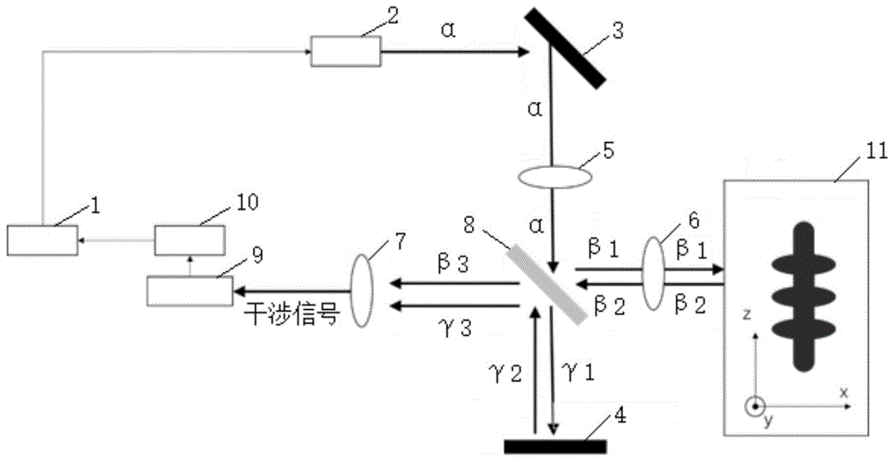
As shown in fig. 1, a first embodiment provides a system for detecting internal defects of a composite insulator, which includes a controller 1, an electromagnetic wave signal source 2, a first reflective glass 3, a second reflective glass 4, a first convex lens 5, a second convex lens 6, a third convex lens 7, a polarization beam splitter 8, a calorimeter 9, and a signal collector 10; the controller 1 is used for sending a control signal to the electromagnetic wave signal source 2 when the composite insulator rotates around the central axis of the current section by a preset angle for each section of the composite insulator; the electromagnetic wave signal source 2 is used for generating an incident signal according to the control signal, and enabling the incident signal to sequentially pass through the first reflecting glass 3 and the first convex lens 5 and reach the polarization beam splitter 8; the polarization beam splitter 8 is configured to split an incident signal into a first refraction signal and a first transmission signal, make the first refraction signal reach the composite insulator through the second convex lens 6, make the first transmission signal reach the second reflective glass 4, and transmit a second transmission signal formed by the first reflection signal on the polarization beam splitter 8 and a second refraction signal formed by the second reflection signal on the polarization beam splitter 8 to the third convex lens 7 when acquiring a first reflection signal generated after the first refraction signal reaches the composite insulator and a second reflection signal generated after the first transmission signal reaches the second reflective glass 4; the calorimeter 9 is used for acquiring an interference signal formed by interference of the second transmission signal and the second refraction signal on the third convex lens 7, and forwarding the interference signal to the controller 1 through the signal collector 10; the controller 1 is further configured to perform defect detection according to all received interference signals after the composite insulator rotates around the central axis of the current cross section for one circle, to generate a two-dimensional distribution map of the internal defects of the current cross section, and generate a three-dimensional distribution map of the internal defects of the composite insulator according to the two-dimensional distribution map of the internal defects of all cross sections after the composite insulator rotates around the central axis of each cross section for one circle.
It should be noted that the cross section is a cross section of the composite insulator specified according to actual detection requirements, or a cross section of the composite insulator at a detection position after moving a preset distance in the radial direction.
As an example, the controller 1 monitors the position state of the composite insulator, and if it is monitored that a section of the composite insulator is at a detection position, transmits a control signal to the electromagnetic wave signal source 2 every time the composite insulator rotates by a preset angle around a central axis of the current section, which is equivalent to transmitting a control signal once when the composite insulator rotates once.
When receiving the control signal sent by the controller 1, the electromagnetic wave signal source 2 generates an incident signal α, such as a frequency sweep signal, according to the control signal, and transmits the incident signal α to the first reflective glass 3, so that the first reflective glass 3 transmits the incident signal α to the first convex lens 5, and the first convex lens 5 transmits the incident signal α to the polarization beam splitter 8.
The polarization beam splitter 8 splits the incident signal α into a first refraction signal β 1 and a first transmission signal γ 1, transmits the first refraction signal β 1 to the second convex lens 6, causes the second convex lens 6 to transmit the first refraction signal β 1 to the composite insulator, meanwhile, the first transmission signal gamma 1 is transmitted to the second reflecting glass 4, and a first reflection signal beta 2 generated after the first reflection signal beta 1 reaches the composite insulator is obtained, and a second reflection signal gamma 2 generated after the first transmission signal gamma 1 reaches the second reflection glass 4, the second transmitted signal beta 3 formed by the first reflected signal beta 2 on the polarizing beam splitter 8, and the second reflected signal gamma 3 formed by the second reflected signal gamma 2 on the polarizing beam splitter 8 is passed to the third convex lens 7, so that the second transmission signal β 3 and the second refraction signal γ 3 interfere on the third convex lens 7 to form an interference signal.
The calorimeter 9 acquires an interference signal formed by interference of the second transmission signal β 3 and the second refraction signal γ 3 on the third convex lens 7, and sends the interference signal to the signal collector 10, so that the signal collector 10 forwards the interference signal to the controller 1.
The controller 1 performs defect detection according to all received interference signals after the composite insulator rotates around the central axis of the current section for one circle, determines the internal defects and defect positions of the current section, generates a two-dimensional distribution map of the internal defects of the current section, and generates a three-dimensional distribution map of the internal defects of the composite insulator according to the two-dimensional distribution map of the internal defects of all sections after the composite insulator rotates around the central axis of each section for one circle, namely the two-dimensional distribution map of the internal defects of all sections.
According to the method, each section of the composite insulator is scanned by adopting electromagnetic waves to obtain interference signals fed back by each section of the composite insulator, the internal defect and the defect position of each section are determined according to the interference signals fed back by each section respectively to draw the two-dimensional distribution map of the internal defect of each section, and then the three-dimensional distribution map of the internal defect of the composite insulator is generated according to the two-dimensional distribution maps of the internal defects of all sections.
In the embodiment, the convex lens is adopted to converge the signal light waves on each signal light path, so that the diameter of the signal light beams is reduced, and the intensity and the resolution of the signals are improved.
In a preferred embodiment, after the composite insulator rotates around the central axis of the current cross section for one circle, defect detection is performed according to all received interference signals, so as to generate a two-dimensional distribution map of internal defects of the current cross section, specifically: performing IFFT (inverse fast Fourier transform) on the signal spectrogram of each interference signal to obtain a depth distribution map corresponding to each interference signal; determining the boundary of the internal defect according to each depth distribution map, and calculating the distance between the boundary of the internal defect and the boundary of the composite insulator; and drawing a two-dimensional distribution map of the internal defects of the current section according to all the distances.
Illustratively, after the composite insulator rotates a circle around the central axis of the current section and a plurality of detection points on the circumference of the current section are scanned, all interference signals fed back by the current section are received, IFFT (inverse Fourier transform) is respectively carried out on a signal spectrogram of each interference signal to obtain a depth distribution diagram corresponding to each interference signal, the boundary of the internal defect is distinguished according to each depth distribution diagram, the distance between the boundary of the internal defect and the left boundary of the composite insulator is calculated, the distance between the boundary of the internal defect and the right boundary of the composite insulator is calculated, the internal defect and the defect position of the current section are determined according to all the obtained distances, and a two-dimensional distribution diagram of the internal defect of the current section is drawn.
In the embodiment, single-point detection is carried out on each detection point on the circumference of each section, the boundary of the internal defect is distinguished according to the interference signal obtained by scanning each detection point, the defect position of each internal defect is positioned by combining the distance relation between the boundary of each internal defect and the left and right boundaries of the composite insulator, the two-dimensional distribution map of the internal defect of the current section is conveniently drawn, the distribution condition of each internal defect of the section can be intuitively known, and the internal defect of the composite insulator can be efficiently and accurately detected.
In a preferred embodiment, before the performing defect detection according to all the received interference signals and generating a two-dimensional distribution map of the current cross-section internal defects, the method further includes: error calibration is performed for each interference signal.
In a preferred implementation manner of this embodiment, the performing error calibration on each interference signal specifically includes: and carrying out error calibration on each interference signal through a pre-established calibration model.
Wherein, the calibration model is:
in the formula (1), D
kIs the ratio of the interference signal intensity to the signal source intensity, L is the number of boundaries,
A
lfor the first intermediate variable calculated before reaching the composite insulator,
A
l *for the first intermediate variable calculated after reaching the composite insulator,
γ
l κa second intermediate variable calculated for the kth beam before it reaches the composite insulator,
γ
l *κa second intermediate variable, a, calculated after the k-th beam has reached the composite insulator
l=(n
l+1-n
l)/(n
l+1+n
l) Is the reflectivity of the l-th boundary, n
lIs the refractive index of the ith boundary,
proportional to the length of the optical path to the l-th boundary, z
pIs a geometric length, n
pIs refractive index, k
minIs the minimum wavelength of the light source,
Δklet κ be the beam sequence number.
In the embodiment, before defect detection is performed according to all interference signals, error calibration is performed on each interference signal through a pre-established calibration model, so that the internal defects of the composite insulator can be further accurately detected.
In a preferred embodiment, the internal defect detection system of the composite insulator further comprises a workbench 11; and the workbench 11 is used for fixing the composite insulator, driving the composite insulator to move a preset distance along the radial direction, enabling one section of the composite insulator to be located at a detection position, and driving the composite insulator to rotate a preset angle along the central axis of the current section.
Illustratively, the workbench 11 drives the composite insulator to move a preset distance along a radial direction, so that a first section of the composite insulator is at a detection position, the composite insulator is driven to rotate by a preset angle along a central axis of the first section, a first detection point on the circumference of the first section is aligned with the detection position for defect detection, the composite insulator is continuously driven to rotate by a preset angle along the central axis of the first section, a second detection point on the circumference of the first section is aligned with the detection position for detection, and according to the operation, the composite insulator is driven to rotate by the preset angle along the central axis of the first section, a last detection point on the circumference of the first section is aligned with the detection position for detection, and the composite insulator is driven to rotate by one circle around the central axis of the first section.
The workbench 11 continues to drive the composite insulator to move a preset distance along the radial direction, so that the second section of the composite insulator is located at the detection position, the composite insulator is driven to rotate for a preset angle for multiple times along the central axis of the second section, and the composite insulator is driven to rotate for a circle around the central axis of the second section.
According to the operation, the composite insulator is driven to move for a preset distance along the radial direction, the last section of the composite insulator is located at the detection position, the composite insulator is driven to rotate for a preset angle for multiple times along the central axis of the last section, and the composite insulator is driven to rotate for a circle around the central axis of the last section.
In the embodiment, the workbench 11 is additionally arranged to drive the composite insulator to move and rotate, so that each detection point on the circumference of each section of the composite insulator can be aligned to the detection position, and the internal defect of the composite insulator can be further efficiently and accurately detected.
In the preferred embodiment, the electromagnetic wave signal source 2 is comprised of a signal generator, a frequency multiplier, an isolator and a horn antenna, as shown in figure 2.
In a preferred embodiment, the first reflective glass 3 and the second reflective glass 4 are both oxidized tin oxide transparent oxide film glasses.
In the embodiment, the transparent oxidized tin film glass is used as the first reflecting glass 3 and the second reflecting glass 4, so that the advantage of high reflectivity of the transparent oxidized tin film glass can be utilized, the radiation energy of signals can be saved as much as possible, and the internal defect detection precision of the composite insulator can be improved.
In a preferred embodiment, the incident signal is a swept frequency signal; wherein, the frequency range of the sweep frequency signal is 50-120GHz, and the sweep frequency interval is 0.05-0.1 GHz.
To better explain the internal defect detection system of the composite insulator provided by the first embodiment, a computer is selected as the controller 1, and the controller 1 controls the electromagnetic wave signal source 2 to emit THz electromagnetic waves, wherein the electromagnetic wave signal source 2 is composed of a signal generator, a frequency amplifier, an isolator and a horn antenna, as shown in fig. 2. The electromagnetic wave signal source 2 generates a sweep frequency signal with a frequency range of 50-120GHz and a sweep frequency interval of 0.05-0.1GHz, namely an incident signal alpha. An incident signal α (electromagnetic wave) is refracted through the first reflective glass 3 and enters the first convex lens 5, and then is split into two electromagnetic waves perpendicular to each other, i.e., a first refraction signal β 1 and a first transmission signal γ 1, by the polarization beam splitter 8. The first refraction signal beta 1 is emitted to the detected composite insulator sample through the second convex lens 6, and the first transmission signal gamma 1 is emitted to the second reflecting glass 4. The first refraction signal beta 1 is reflected back to the first reflection signal beta 2 after reaching the composite insulator, and the first transmission signal gamma 1 is reflected back to the second reflection signal gamma 2 after reaching the second reflection glass 4. The first reflected signal β 2 generates a second transmitted signal β 3 through the polarization beam splitter 8, and the second transmitted signal β 3 enters the third convex lens 7, and the second reflected signal γ 2 generates a second refracted signal γ 3 through the polarization beam splitter 8, and the second refracted signal γ 3 enters the third convex lens 7. The second transmission signal β 3 and the second refraction signal γ 3 interfere with each other at the third convex lens 7 to form an interference signal. The interference signal is measured by the calorimeter 9 and the measured interference signal enters the controller 1 through the signal collector 10.
The composite insulator is fixed on a worktable 11 and can move along the axis (z axis) of the composite insulator or rotate around the axis (z axis), and electromagnetic waves irradiate the composite insulator from the radial direction in the measurement process, as shown in figure 1.
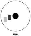
When no defect exists in the composite insulator umbrella skirt, the refractive index in the composite insulator umbrella skirt is a constant n which is uniform and unchanged. When the defects such as air holes exist inside the composite insulator, the defects such as the air holes have different refractive indexes from those of the umbrella skirt substrate, and the composite insulator is considered to be a multilayer object composed of substances with different refractive indexes. Fig. 3 is a schematic diagram of a cross section of a composite insulator, in which 2 square air hole defects exist, THz electromagnetic waves irradiate the composite insulator from an antenna, and first pass through air (refractive index n1), then reach a shed base body (composite material, refractive index n2), then reach an air hole (refractive index n3 ═ n1), and then reach the base body and subsequent air holes. The electromagnetic wave has different reflectivity in the air and the umbrella skirt base body and is reflected at the interface, so that an interference signal is obtained.
The signal spectrogram of the received interference signal is modeled by a pre-established calibration model, namely equation (1):
in the formula (1), D
kIs the ratio of the interference signal intensity to the signal source intensity, L is the number of boundaries,
A
lfor the first intermediate variable calculated before reaching the composite insulator,
A
l *for the first intermediate variable calculated after reaching the composite insulator,
γ
l κa second intermediate variable calculated for the kth beam before it reaches the composite insulator,
γ
l *κa second intermediate variable, a, calculated after the k-th beam has reached the composite insulator
l=(n
l+1-n
l)/(n
l+1+n
l) Is the reflectivity of the l-th boundary, n
lIs the refractive index of the ith boundary,
proportional to the length of the optical path to the l-th boundary, z
pIs a geometric length, n
pIs refractive index, k
minIs the minimum wavelength of the light source,
Δkis the step size of the beam, and κ is the beam sequence number.
Fig. 4 is a signal spectrum of an interference signal obtained by manually setting a defect in the composite insulator, where the abscissa is a frequency range of electromagnetic wave frequency sweep, and the ordinate is normalized signal intensity, and corresponds to distances of the air hole from the insulator boundary of 1mm, 2mm, 3mm, 5mm, and 10mm, respectively.
Firstly, modeling a signal spectrogram of an interference signal obtained by artificially setting defects in a composite insulator through a pre-established calibration model to obtain a theoretical signal spectrogram of the interference signal, calculating the number of waveforms between 50 and 100GHz, such as x periodic segments, measuring the artificial defects to obtain an actual signal spectrogram of the interference signal, calculating the number of waveforms between 50 and 100GH, such as y segments, wherein if x is y, the error correction is not needed, and if x is not y, the correction is needed to be carried out on the actual signal spectrogram of the interference signal through a computer, and the actual signal spectrogram of the interference signal is stretched or compressed along the abscissa direction. Error calibration can be accomplished by measuring only one artificial defect.
The signal spectrogram of the interference signal is subjected to IFFT (inverse fourier transform) to obtain a depth distribution diagram as shown in fig. 5, where the distance of the first spectrum is the path taken by the electromagnetic wave to reach the first boundary of the composite insulator, and the distance of the second spectrum is the path taken by the electromagnetic wave to reach the 2 nd boundary of the composite insulator, i.e., the left boundary of the air hole. Since the distance from the edge of the shed of the composite insulator to the core rod is known, only a depth distribution diagram from the starting point of the electromagnetic wave to the core rod is required to be cut. Likewise, the distance to the right boundary of the air hole can be calculated.
Fig. 4 and 5 correspond to the air hole with a crack having a width much smaller than 1mm, and the distance from the left boundary to the right boundary of the air hole is small and cannot be distinguished. The abscissa in fig. 5 is the distance traveled by the electromagnetic wave, the 1 st spectrum corresponds to the boundary of the composite insulator, the second spectrum corresponds to the left boundary of the air hole, and the right boundary is too close to the left boundary to be distinguished. Only when the left and right boundaries of the vent are large, there will be a 3 rd spectrum in fig. 5, corresponding to the right boundary of the vent. Figure 5 therefore also reflects that the optimum resolution of the system is to around 1-2 mm.
And rotating the composite insulator along the z axis for 1 degree after one detection point of the composite insulator is swept once, performing secondary scanning, and scanning for multiple times to obtain the distance between the outer edge of the composite insulator and the boundary of the internal defect, and drawing a two-dimensional scanning image of the section according to the distance.
It will be appreciated that the two-dimensional scan of the defect-free section is shown in figure 6 and the two-dimensional scans of the defect sections 1, 2, 3 are shown in figures 7-9 respectively.
After a section is scanned, the composite insulator is moved for a preset distance along the z axis, and a two-dimensional scanning image of the section is obtained after the composite insulator is scanned for one circle according to the same operation, so that a three-dimensional distribution map of the air holes is obtained by scanning a plurality of sections.
Based on the same inventive concept as the first embodiment, the second embodiment provides a method for detecting internal defects of a composite insulator as shown in fig. 10, which is suitable for the system for detecting internal defects of a composite insulator as described in the first embodiment, and includes steps S1 to S5:
s1, the controller 1 sends a control signal to the electromagnetic wave signal source 2 when the composite insulator rotates a preset angle around the central axis of the current section for each section of the composite insulator;
s2, the electromagnetic wave signal source 2 generates an incident signal according to the control signal, and the incident signal sequentially passes through the first reflecting glass 3 and the first convex lens 5 to reach the polarization beam splitter 8;
s3, the polarization beam splitter 8 decomposes the incident signal into a first refraction signal and a first transmission signal, the first refraction signal reaches the composite insulator through the second convex lens 6, the first transmission signal reaches the second reflection glass 4, and when a first reflection signal generated after the first refraction signal reaches the composite insulator and a second reflection signal generated after the first transmission signal reaches the second reflection glass 4 are obtained, a second transmission signal formed by the first reflection signal on the polarization beam splitter 8 and a second refraction signal formed by the second reflection signal on the polarization beam splitter 8 are transmitted to the third convex lens 7;
s4, the calorimeter 9 obtains an interference signal formed by interference of the second transmission signal and the second refraction signal on the third convex lens 7, and the interference signal is forwarded to the controller 1 through the signal collector 10;
and S5, the controller 1 performs defect detection according to all the received interference signals after the composite insulator rotates around the central axis of the current section for one circle, so as to generate a two-dimensional distribution map of the internal defects of the current section, and generates a three-dimensional distribution map of the internal defects of the composite insulator according to the two-dimensional distribution map of the internal defects of all the sections after the composite insulator rotates around the central axis of each section for one circle.
In a preferred embodiment, after the composite insulator rotates around the central axis of the current cross section for one circle, defect detection is performed according to all received interference signals, so as to generate a two-dimensional distribution map of internal defects of the current cross section, specifically: performing IFFT (inverse fast Fourier transform) on the signal spectrogram of each interference signal to obtain a depth distribution map corresponding to each interference signal; determining the boundary of the internal defect according to each depth distribution map, and calculating the distance between the boundary of the internal defect and the boundary of the composite insulator; and drawing a two-dimensional distribution map of the internal defects of the current section according to all the distances.
In a preferred embodiment, before the performing defect detection according to all the received interference signals and generating a two-dimensional distribution map of the current cross-section internal defects, the method further includes: error calibration is performed for each interference signal.
In a preferred implementation manner of this embodiment, the performing error calibration on each interference signal specifically includes: and carrying out error calibration on each interference signal through a pre-established calibration model.
In a preferred embodiment, the internal defect detection system of the composite insulator further comprises a workbench 11; and the workbench 11 is used for fixing the composite insulator, driving the composite insulator to move a preset distance along the radial direction, enabling one section of the composite insulator to be located at a detection position, and driving the composite insulator to rotate a preset angle along the central axis of the current section.
In the preferred embodiment, the electromagnetic wave signal source 2 is composed of a signal generator, a frequency multiplier, an isolator and a horn antenna.
In a preferred embodiment, the first reflective glass 3 and the second reflective glass 4 are both oxidized tin oxide transparent oxide film glasses.
In a preferred embodiment, the incident signal is a swept frequency signal; wherein, the frequency range of the sweep frequency signal is 50-120GHz, and the sweep frequency interval is 0.05-0.1 GHz.
In summary, the embodiment of the present invention has the following advantages:
by designing a composite insulator internal defect detection system, a controller 1 is utilized to send a control signal to an electromagnetic wave signal source 2 when the composite insulator rotates a preset angle around the central axis of the current section for each section of the composite insulator, the electromagnetic wave signal source 2 is utilized to generate an incident signal according to the control signal, the incident signal sequentially passes through a first reflecting glass 3 and a first convex lens 5 to reach a polarization beam splitter 8, the polarization beam splitter 8 is utilized to decompose the incident signal into a first refraction signal and a first transmission signal, the first refraction signal passes through a second convex lens 6 to reach the composite insulator, the first transmission signal reaches a second reflecting glass 4, and when a first reflection signal generated after the first refraction signal reaches the composite insulator and a second reflection signal generated after the first transmission signal reaches the second reflecting glass 4 are obtained, transmitting a second transmission signal formed by the first reflection signal on the polarization beam splitter 8 and a second refraction signal formed by the second reflection signal on the polarization beam splitter 8 to a third convex lens 7, acquiring an interference signal formed by interference of the second transmission signal and the second refraction signal on the third convex lens 7 by using a calorimeter 9, forwarding the interference signal to the controller 1 by using a signal collector 10, and transmitting the interference signal to the controller 1 by using the controller 1, after the composite insulator rotates a circle around the central axis of the current section, defect detection is carried out according to all received interference signals to generate a two-dimensional distribution map of the internal defects of the current section, after the composite insulator rotates a circle around the central axis of each section, and generating a three-dimensional distribution map of the internal defects of the composite insulator according to the two-dimensional distribution map of the internal defects of all the sections, thereby realizing the detection of the internal defects of the composite insulator. According to the embodiment of the invention, each section of the composite insulator is scanned by adopting electromagnetic waves to obtain the interference signals fed back by each section of the composite insulator, the internal defect and the defect position of each section are determined according to the interference signals fed back by each section respectively to draw the two-dimensional distribution map of the internal defect of each section, and then the three-dimensional distribution map of the internal defect of the composite insulator is generated according to the two-dimensional distribution maps of the internal defects of all sections.
While the foregoing is directed to the preferred embodiment of the present invention, it will be understood by those skilled in the art that various changes and modifications may be made without departing from the spirit and scope of the invention.
It will be understood by those skilled in the art that all or part of the processes in the above embodiments may be implemented by hardware related to instructions of a computer program, where the computer program may be stored in a computer readable storage medium, and when executed, the computer program may include the processes in the above embodiments. The storage medium may be a magnetic disk, an optical disk, a Read-Only Memory (ROM), a Random Access Memory (RAM), or the like.