CN114043147A - Large-scale curb girder constitution equipment child - Google Patents
Large-scale curb girder constitution equipment child Download PDFInfo
- Publication number
- CN114043147A CN114043147A CN202111253656.0A CN202111253656A CN114043147A CN 114043147 A CN114043147 A CN 114043147A CN 202111253656 A CN202111253656 A CN 202111253656A CN 114043147 A CN114043147 A CN 114043147A
- Authority
- CN
- China
- Prior art keywords
- assembly
- side beam
- platform
- positioning support
- pressing
- Prior art date
- Legal status (The legal status is an assumption and is not a legal conclusion. Google has not performed a legal analysis and makes no representation as to the accuracy of the status listed.)
- Pending
Links
Images


Classifications
-
- B—PERFORMING OPERATIONS; TRANSPORTING
- B23—MACHINE TOOLS; METAL-WORKING NOT OTHERWISE PROVIDED FOR
- B23K—SOLDERING OR UNSOLDERING; WELDING; CLADDING OR PLATING BY SOLDERING OR WELDING; CUTTING BY APPLYING HEAT LOCALLY, e.g. FLAME CUTTING; WORKING BY LASER BEAM
- B23K37/00—Auxiliary devices or processes, not specially adapted to a procedure covered by only one of the preceding main groups
- B23K37/04—Auxiliary devices or processes, not specially adapted to a procedure covered by only one of the preceding main groups for holding or positioning work
- B23K37/0426—Fixtures for other work
- B23K37/0435—Clamps
-
- B—PERFORMING OPERATIONS; TRANSPORTING
- B23—MACHINE TOOLS; METAL-WORKING NOT OTHERWISE PROVIDED FOR
- B23K—SOLDERING OR UNSOLDERING; WELDING; CLADDING OR PLATING BY SOLDERING OR WELDING; CUTTING BY APPLYING HEAT LOCALLY, e.g. FLAME CUTTING; WORKING BY LASER BEAM
- B23K31/00—Processes relevant to this subclass, specially adapted for particular articles or purposes, but not covered by only one of the preceding main groups
- B23K31/003—Processes relevant to this subclass, specially adapted for particular articles or purposes, but not covered by only one of the preceding main groups relating to controlling of welding distortion
-
- B—PERFORMING OPERATIONS; TRANSPORTING
- B23—MACHINE TOOLS; METAL-WORKING NOT OTHERWISE PROVIDED FOR
- B23K—SOLDERING OR UNSOLDERING; WELDING; CLADDING OR PLATING BY SOLDERING OR WELDING; CUTTING BY APPLYING HEAT LOCALLY, e.g. FLAME CUTTING; WORKING BY LASER BEAM
- B23K31/00—Processes relevant to this subclass, specially adapted for particular articles or purposes, but not covered by only one of the preceding main groups
- B23K31/02—Processes relevant to this subclass, specially adapted for particular articles or purposes, but not covered by only one of the preceding main groups relating to soldering or welding
Abstract
The invention relates to the technical field of manufacturing equipment, in particular to an assembly jig for large side beam assemblies, which comprises a platform, a portal frame, a guide rail, a positioning support assembly and a clamping assembly, wherein a pressing device for calibrating and controlling local deformation of the side beam is slidably arranged on the portal frame, the positioning support assembly is used for positioning and supporting the horizontal direction and the bottom surface of the side beam, the clamping assembly is used for fixing and locking the side beam, the modular design is used, the large cross beam assembly and welding piece multi-variety alternative production is facilitated, the universality is strong, the component preassembling precision is ensured by the positioning support assembly which is easy to disassemble and assemble, the welding deformation in the welding process of a long straight welding line is reduced by the pressing device, a plurality of adjusting columns are further arranged on the side edges, the local position of the side beam assembly component is corrected, the precision requirement of the side beam assembly finished product is effectively ensured at the same time, and workers can alternately exchange stations by symmetrically arranging two mounting stations, the division of labor is cooperated, the two sides are processed simultaneously, the batch operation is realized, and the production efficiency of the side beam assembly is greatly improved.
Description
Technical Field
The invention relates to the technical field of manufacturing equipment, in particular to an assembly jig consisting of large side beams.
Background
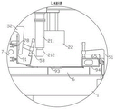
A certain model flatcar is different from traditional individual layer flatcar in body structure, there is not the centre sill behind this car body pillow, lateral wall bearing structure for the bent type, nearly 16 meters of length is constituteed to the curb girder, by first sill 91, second sill 92, web 93, roof side rail 94, little side pillar 95, big side pillar 96, well side pillar 97, end plate 98, 99 assembly welding of curb girder form, first sill 91 is the fillet bent plate, second sill 92 is L type bent plate, web 93 is the big board of taking the hem, roof side rail 94 is the square steel structure, little side pillar 95 is the channel-section steel structure of trough of belt. The web plates 93 are assembled outside the side columns and are in a streamline shape, and the control of the assembly size of the side beam assembly is the key in the assembly of the vehicle body in the manufacturing process, so that the control of the side beam assembly as a key process is particularly important, but the existing tooling equipment is difficult to meet the batch operation of the assembly of the side beam assembly, the assembled parts are stacked on the site in batches, the quality hidden danger of the vehicle body assembly is caused by simple tooling, and the production process is not smooth.
The side beam assembly is generally manufactured on a platform in the early production, and is assembled by measuring, positioning and assembling a backer and a measuring tape. The assembly sequence is as follows: web 93 → first bottom rail 91 → second bottom rail 92 → end plate 98 → roof rail 94 → large side column 96 → side beam 99 → small side column 95, middle column 97. However, the side beam assembly is mainly formed by welding plates, bending pieces, profiles and the like with different thicknesses, the side beam assembly is curved, the length is long, the lateral area is large, the blanking deformation and the bending precision are influenced, the assembly precision and the design of the side beam assembly on the platform are difficult to keep the same, the detection and correction difficulty is large due to the curved structure, a large-scale pressing device is lacked, the welding deformation is large, and the assembly and the welded size of the side beam assembly are difficult to control.
Disclosure of Invention
In order to overcome the defects of the prior problems, the invention provides an assembly tire for a large side beam assembly.
The technical scheme adopted by the invention for solving the technical problems is as follows: the utility model provides an equipment child is constituteed to large-scale curb girder, includes platform, portal frame, guide rail, location supporting component and clamping unit, be on a parallel with platform length direction interval on the top surface of platform and be equipped with a plurality of mounting grooves on, its side interval is equipped with a plurality of side mounting grooves, location supporting component fixes on the platform through last mounting groove, the guide rail sets up in the platform both sides along platform length direction, the portal frame walking is installed on the guide rail, slidable mounting has the push-down device that is used for calibration and control curb girder local deformation on the portal frame, location supporting component is used for the location and the support of curb girder horizontal direction and bottom surface, clamping unit is used for fixed locking curb girder.
Specifically, the positioning support assembly is used for positioning and installing products, and the positioning support assembly and the clamping assembly are detachably fixed on the platform and can be replaced according to different product requirements. The portal frame can move back and forth along the guide rail, and parts and assemblies formed by the side beams are calibrated in the assembling or welding process or local areas are compacted, so that the welding deformation is reduced. The side beam component is quickly positioned by using the special supporting component, so that the assembly precision is ensured, the welding deformation is reduced, and the welding efficiency and quality are ensured.
According to another embodiment of the invention, the pressing device further comprises a pressing base body and a pressing head, and the pressing head is installed in the pressing base body in a sliding mode along the vertical direction.
According to another embodiment of the invention, the gantry is slidably provided with an automatic welding unit, and the automatic welding unit is provided with a welding manipulator and is used for continuously and automatically welding along the traveling direction of the gantry.
Through setting up automatic weld unit and welding machines hand, can be in succession automatic weld when the portal frame walking, reduce workman's amount of labour, improve welding efficiency, guarantee simultaneously and stabilize welding and welding quality.
According to another embodiment of the invention, the portal frames are provided with two groups, wherein two groups of pressing devices are arranged on one group of portal frames, and two groups of automatic welding units are arranged on the other group of portal frames.
Through setting up two sets of push down device and two sets of automatic weld unit, can compress tightly and automatic weld simultaneously the welding position of two welding seams, two portal frames alternate movement accomplish the welding on the whole length, improve welding efficiency and quality.
According to another embodiment of the present invention, the positioning and supporting assembly further includes a plurality of first bases and second bases arranged in parallel and at intervals along the width direction of the platform, the first bases are provided with a first supporting surface, a second supporting surface, a first backrest and a second backrest, and the second bases are provided with a third supporting surface, a fourth supporting surface, a fifth supporting surface, a third backrest, a fourth backrest and a fifth backrest.
Through setting up holding surface and backer, for the curb girder component part provides stable support and accurate positioning, guarantee to constitute welding precision, shorten alignment adjustment time.
According to another embodiment of the invention, the first adjusting column is horizontally arranged on one side of the first backer, the second adjusting column is horizontally arranged on one side of the third backer, the at least one third adjusting column is horizontally arranged on one side of the fifth backer, and the first adjusting column, the second adjusting column and the third adjusting column are installed on the first base and the second base in a threaded fit manner.
Through setting up the adjustment post, can rectify the local position that zero subassembly was constituteed to the curb girder, guarantee that the side amount of deflection on the whole length direction meets the requirements, guarantee to constitute welding precision.
According to another embodiment of the present invention, it is further included that the positioning support assembly is a symmetrical structure for simultaneously mounting two side members.
Set up two installation stations through the symmetry, can carry out spare part equipment, welding in turn on platform both sides, equipment staff and welding staff can exchange the station in turn, and staff divides the work of labor cooperation, mutually noninterfere, when one side hoist and mount, installation, adjustment welding spare part, carries out welding process at the opposite side, realizes batch operation, has improved the curb girder greatly and has constituteed production efficiency.
According to another embodiment of the invention, the clamping assembly comprises a plurality of single-side quick pressing assemblies, a G-shaped clamp and a double-side quick pressing assembly, the single-side quick pressing assemblies are used for pressing the upper edge beam and are fixed on the upper mounting groove, the G-shaped clamp is used for clamping the first lower edge beam, and the double-side quick pressing assemblies are used for clamping the first lower edge beam and the second lower edge beam and are fixed in the middle of the platform.
Through using conventional clamp, arrange the tight position of clamp according to the product demand is nimble, improve the operating efficiency. By using the quick pressing assembly clamp, the welding parts can be quickly installed, clamped and detached.
The invention has the advantages that the modular design is used, the large-scale beam assembly and welding piece can be conveniently and alternately produced in multiple varieties, the universality is strong, the pre-installation precision of parts is ensured through the positioning support assembly which is easy to disassemble and assemble, only part of the base needs to be modified or replaced when the product is modified and upgraded, the product is convenient to update, meanwhile, the pressing device which can be adjusted and moved on the whole welding plane is arranged, the welding deformation in the welding process of the long and straight welding line is reduced, the side edge is also provided with a plurality of adjusting columns, the local position of the side beam assembly part is corrected, the precision requirement of the part assembly is properly reduced, the precision requirement of the side beam assembly part is effectively ensured, the two installation stations are symmetrically arranged, workers can alternately exchange the stations, work in a time division manner, the two sides are simultaneously treated, the batch operation is realized, and the production efficiency of the side beam assembly is greatly improved.
Drawings
The invention is further illustrated with reference to the following figures and examples.
FIG. 1 is a schematic view of the construction of the side beam assembly;
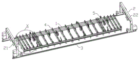
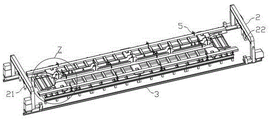
FIG. 2 is a schematic structural view of the present invention;
FIG. 3 is an enlarged view at X in FIG. 2;
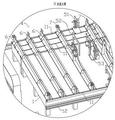
FIG. 4 is a schematic view of the present invention with only the web, roof rail and first sill mounted to one side thereof;
FIG. 5 is an enlarged view at Y in FIG. 4;
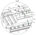
FIG. 6 is a schematic view of the side sill as a finished welded assembly;
FIG. 7 is an enlarged view at Z in FIG. 6;
FIG. 8 is a side schematic view of FIG. 4;
FIG. 9 is an enlarged view at L of FIG. 8;
FIG. 10 is a side schematic view of FIG. 6;
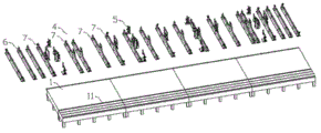
FIG. 11 is an exploded view of a portion of the present invention;
FIG. 12 is a schematic view of a first base;
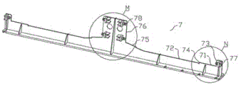
FIG. 13 is a schematic view of a second mount;
FIG. 14 is an enlarged view at M of FIG. 13;
FIG. 15 is an enlarged view at N of FIG. 13;
FIG. 16 is a schematic view of a single side quick press assembly;
FIG. 17 is a schematic view of a G-clip 52;
FIG. 18 is a schematic view of a dual sided snap action assembly.
In the figure, a platform 1, an upper mounting groove 11, a side mounting groove 12, a portal frame 2, a lower pressing device 21, a lower pressing base 211, a lower pressing head 212, an automatic welding unit 22, a guide rail 3, a positioning support component 4, a clamping component 5, a single-side fast pressing component 51, a first base 511, a first curved arm 512, a first pressing column 513, a first pin 514, a G-shaped clamp 52, a second base 521, a second pressing column 522, a positioning part 523, a double-side fast pressing component 53, a third base 531, a third pressing column 532, a first base 6, a first supporting surface 61, a second supporting surface 62, a first backer 63, a second backer 64, a first adjusting column 65, a second base 7, a third supporting surface 71, a fourth supporting surface 72, a fifth supporting surface 75, a third backer 73, a fourth backer 74, a fifth backer 76, a second adjusting column 77, a third adjusting column 78, a first lower side beam 91, a second web lower side beam 93, roof side rail 94, small side column 95, large side column 96, middle side column 97, end plate 98, side rail 99.
Detailed Description
As shown in fig. 2-18, which are schematic structural diagrams of the present invention, an assembly jig for assembling large side beams includes a platform 1, a gantry 2, a guide rail 3, a positioning support assembly 4 and a clamping assembly 5, wherein a plurality of upper mounting grooves 11 are formed on the top surface of the platform 1 at intervals in a direction parallel to the length direction of the platform 1, a plurality of side mounting grooves 12 are formed on the side edges of the platform at intervals, the positioning support assembly 4 is fixed on the platform 1 through the upper mounting grooves 11, the guide rail 3 is arranged on both sides of the platform 1 along the length direction of the platform 1, the gantry 2 is installed on the guide rail 3 in a walking manner, a pressing device 21 for calibrating and controlling local deformation of the side beams is slidably installed on the gantry 2, the positioning support assembly 4 is used for positioning and supporting the horizontal direction and the bottom surface of the side beams, and the clamping assembly 5 is used for fixing and locking the side beams.
Go up mounting groove 11 and side mounting groove 12 and can be T type groove, and be on a parallel with 1 length direction of platform and set up many, conveniently according to the size adjustment mounted position of location supporting component 4. The portal frame 2 can move back and forth on the guide rail 3, and the pressing device 21 moves on the portal frame 2 along the width direction of the platform 1 to adjust the pressing position. Platform 1 sets up the take the altitude, makes things convenient for operating personnel to stand work around the platform.
Preferably, the pressing device 21 includes a pressing base 211 and a pressing ram 212, and the pressing ram 212 is slidably mounted in the pressing base 211 along a vertical direction.
The pressing device 21 may be a hydraulic driving structure, and the plunger drives the pressing ram 212 to move up and down.
Preferably, an automatic welding unit 22 is slidably mounted on the gantry 2, and a welding manipulator is arranged on the automatic welding unit 22 and is used for continuous automatic welding along the traveling direction of the gantry 2.
The automatic welding unit 22 is provided with a conventional welding robot or automatic welding device.
Preferably, the two sets of portal frames 2 are provided, one set of portal frame 2 is provided with two sets of pressing devices 21, and the other set of portal frame 2 is provided with two sets of automatic welding units 22.
Preferably, the positioning support assembly 4 includes a plurality of first bases 6 and second bases 7 arranged in parallel at intervals along the width direction of the platform 1, the first base 6 is provided with a first support surface 61, a second support surface 62, a first cam 63 and a second cam 64, and the second base 7 is provided with a third support surface 71, a fourth support surface 72, a fifth support surface 75, a third cam 73, a fourth cam 74 and a fifth cam 76.
The first support surface 61 and the third support surface 71 form a support surface for supporting the roof rail 94, and the first rest 63 and the third rest 73 provide lateral positioning for the roof rail 94. The second support surface 62 and the fourth support surface 72 form a support surface for supporting the web 93, and the second and fourth abutments 64 and 74 provide lateral positioning for the web 93. The fifth bearing surface 75 and the fifth backer 76 provide location and support for both sides of the first rocker 91, while the web 93, the roof rail 94, and the first rocker 91 overlap when installed in place.
Preferably, a first adjusting column 65 is horizontally arranged on one side of the first backer 63, a second adjusting column 77 is horizontally arranged on one side of the third supporting surface 71, at least one third adjusting column 78 is horizontally arranged on one side of the fifth backer 76, and the first adjusting column 65, the second adjusting column 77 and the third adjusting column 78 are all installed on the first base 6 and the second base 7 in a threaded fit manner.
The adjusting columns can be arranged on part of the first base 6 and the second base 7, each adjusting column mounting position is provided with a mounting seat, the first adjusting column 65, the second adjusting column 77 and the second adjusting column 77 are all in threaded connection with the mounting seats, and the extension length of the adjusting columns can be adjusted through flat surfaces or hexagonal heads of adjusting column heads so as to abut against the side walls of the upper edge beam 94 and the first lower edge beam 91 and adjust the side deflection of the upper edge beam and the first lower edge beam 91.
Preferably, the positioning and supporting assembly 4 is a symmetrical structure and is used for simultaneously mounting two side beams.
The positioning support member 4 may be a symmetrical structure.
Preferably, the clamping assembly 5 comprises a plurality of single-side quick pressing assemblies 51, a G-shaped clamp 52 and a double-side quick pressing assembly 53, wherein the single-side quick pressing assembly 51 is used for pressing the upper edge beam 94 and is fixed on the upper mounting groove 11, the G-shaped clamp 52 is used for clamping the first lower edge beam 91, and the double-side quick pressing assembly 53 is used for clamping the first lower edge beam 91 and the second lower edge beam 92 and is fixed in the middle of the platform 1.
The single-side quick pressing assembly 51, the G-shaped clamp 52 and the double-side quick pressing assembly 53 can be conventional manual quick pressing tools, and a plurality of single-side quick pressing tools can be arranged along the length direction of the platform 1. Unilateral quick pressing assembly 51 and bilateral quick pressing assembly 53 also can set up to pneumatic automatic clamp, improve clamping efficiency.
The single-side fast pressing assembly 51 comprises a first base 511, a first bent arm 512 is hinged on the first base 511, a first pressing column 513 is screwed at the end of the first bent arm 512, and the other end of the first bent arm 512 is fixed with the first base 511 through a first pin 514. When the pressing device is used, after a workpiece is mounted in place, the first pin 514 is mounted, and then the first pressing column 513 is rotated to a proper position to press the workpiece. When the workpiece is loosened, the first pressing column 513 is loosened slightly, the first pin 514 can be detached, and then the first bent arm 512 is lifted, so that the workpiece to be machined can be lifted conveniently. The single-side quick pressing assembly 51 is mounted in the upper mounting groove 11 and used for pressing the upper end surface of the upper edge beam 94.
The G-shaped clamp 52 is a frame with an opening on one side, and includes a second base 521, one end of the second base 521 is a positioning portion 523, the other end is in threaded connection with a second pressing column 522, and the distance between the end of the second pressing column 522 and the positioning portion 523 is adjusted by rotating to clamp or loosen the workpiece to be machined. The G-clip 52 is adapted to be freely mounted on both sides of the two first rocker beams 91, such that the first rocker beams 91 abut against the fifth bearing surface 75 and the fifth backer 76.
The double-side fast pressing assembly 53 is similar to the single-side fast pressing assembly 51 in structure, but shares the third base 531, and is also provided with a third pressing column 532. The bilateral fast-pressing assembly 53 is used for pressing the lower side of the first lower side beam 91 by means of a channel steel block, and also can be used for pressing the upper end surface of the second lower side beam 92 when the second lower side beam 92 is welded. The bilateral quick-pressing component 53 can be matched with the platform 1 to be fixed by mounting holes.
Each compression leg can be rotated and loosened by penetrating through the steel bar and utilizing lever twisting.
Through providing accurate positioning and reliable compressing tightly to the major structure, can effective control welding deformation, guarantee major structure welding precision. The small side column 95, the large side column 96, the middle side column 97, the end plate 98 and the side beam 99 of other welding parts can form self-positioning, and welding of other small parts can be completed by using a welded surface as a positioning reference or using mutual abutting as a reference and then using a common guiding rule and a standard clamping tool.
The foregoing description is intended to be illustrative rather than limiting, and it will be appreciated by those skilled in the art that many modifications, variations or equivalents may be made without departing from the spirit and scope of the invention as defined in the appended claims.
Claims (8)
1. An assembly jig for large side beam assemblies is characterized by comprising a platform (1), a portal frame (2), a guide rail (3), a positioning support assembly (4) and a clamping assembly (5), a plurality of upper mounting grooves (11) are arranged on the top surface of the platform (1) at intervals in parallel with the length direction of the platform (1), a plurality of side mounting grooves (12) are arranged at intervals on the side edge of the positioning support component (4), the positioning support component is fixed on the platform (1) through an upper mounting groove (11), the guide rails (3) are arranged on two sides of the platform (1) along the length direction of the platform (1), the portal frame (2) is arranged on the guide rail (3) in a walking way, a pressing device (21) for calibrating and controlling the local deformation of the side beam is arranged on the portal frame (2) in a sliding way, the positioning support assembly (4) is used for positioning and supporting the horizontal direction and the bottom surface of the side beam, and the clamping assembly (5) is used for fixing and locking the side beam.
2. The large-sized side sill assembly jig according to claim 1, wherein the hold-down device (21) includes a hold-down base (211) and a hold-down ram (212), and the hold-down ram (212) is slidably mounted in the hold-down base (211) in a vertical direction.
3. The large-scale side beam assembly jig according to claim 1, wherein an automatic welding unit (22) is slidably mounted on the gantry (2), and a welding manipulator is provided on the automatic welding unit (22) and is used for continuous automatic welding along the traveling direction of the gantry (2).
4. The large-scale side beam assembly jig according to claim 3, wherein the portal frames (2) are provided in two sets, one set of the portal frames (2) is provided with two sets of the hold-down devices (21), and the other set of the portal frames (2) is provided with two sets of the automatic welding units (22).
5. The large-scale side beam assembly jig as claimed in claim 1, wherein the positioning support assembly (4) comprises a plurality of first bases (6) and second bases (7) which are arranged in parallel at intervals along the width direction of the platform (1), the first bases (6) are provided with first supporting surfaces (61), second supporting surfaces (62), first buttresses (63) and second buttresses (64), and the second bases (7) are provided with third supporting surfaces (71), fourth supporting surfaces (72), fifth supporting surfaces (75), third buttresses (73), fourth buttresses (74) and fifth buttresses (76).
6. The large-scale side beam assembly jig as claimed in claim 4, wherein a first adjusting column (65) is horizontally arranged on one side of the first backer (63), a second adjusting column (77) is horizontally arranged on one side of the third supporting surface (71), at least one third adjusting column (78) is horizontally arranged on one side of the fifth backer (76), and the first adjusting column (65), the second adjusting column (77) and the third adjusting column (78) are installed on the first base (6) and the second base (7) in a threaded fit manner.
7. The assembly jig for large side member assemblies according to claim 1, wherein the positioning support members (4) are of a symmetrical structure for simultaneously mounting two side member assemblies.
8. The large-scale side beam assembly jig as claimed in claim 1, wherein the clamping assembly (5) comprises a plurality of single-side quick pressing assemblies (51), G-shaped clamps (52) and double-side quick pressing assemblies (53), the single-side quick pressing assemblies (51) are used for pressing the upper side beam (94) and are fixed on the upper mounting groove (11), the G-shaped clamps (52) are used for clamping the first lower side beam (91), and the double-side quick pressing assemblies (53) are used for clamping the first lower side beam (91) and the second lower side beam (92) and are fixed in the middle of the platform (1).
Priority Applications (1)
| Application Number | Priority Date | Filing Date | Title |
|---|---|---|---|
| CN202111253656.0A CN114043147A (en) | 2021-10-27 | 2021-10-27 | Large-scale curb girder constitution equipment child |
Applications Claiming Priority (1)
| Application Number | Priority Date | Filing Date | Title |
|---|---|---|---|
| CN202111253656.0A CN114043147A (en) | 2021-10-27 | 2021-10-27 | Large-scale curb girder constitution equipment child |
Publications (1)
| Publication Number | Publication Date |
|---|---|
| CN114043147A true CN114043147A (en) | 2022-02-15 |
Family
ID=80206104
Family Applications (1)
| Application Number | Title | Priority Date | Filing Date |
|---|---|---|---|
| CN202111253656.0A Pending CN114043147A (en) | 2021-10-27 | 2021-10-27 | Large-scale curb girder constitution equipment child |
Country Status (1)
| Country | Link |
|---|---|
| CN (1) | CN114043147A (en) |
Cited By (2)
| Publication number | Priority date | Publication date | Assignee | Title |
|---|---|---|---|---|
| CN114559674A (en) * | 2022-02-21 | 2022-05-31 | 常州市新创智能科技有限公司 | Sectional type composite material vehicle body assembling tool and assembling process |
| CN114589531A (en) * | 2022-03-25 | 2022-06-07 | 四川艾庞机械科技有限公司 | Synchronous thin plate pressing device and using method thereof |
-
2021
- 2021-10-27 CN CN202111253656.0A patent/CN114043147A/en active Pending
Cited By (2)
| Publication number | Priority date | Publication date | Assignee | Title |
|---|---|---|---|---|
| CN114559674A (en) * | 2022-02-21 | 2022-05-31 | 常州市新创智能科技有限公司 | Sectional type composite material vehicle body assembling tool and assembling process |
| CN114589531A (en) * | 2022-03-25 | 2022-06-07 | 四川艾庞机械科技有限公司 | Synchronous thin plate pressing device and using method thereof |
Similar Documents
| Publication | Publication Date | Title |
|---|---|---|
| CN114043147A (en) | Large-scale curb girder constitution equipment child | |
| JPH0375279B2 (en) | ||
| CN107498163B (en) | Production process and production equipment of steel plate wall component | |
| CN216541578U (en) | Large-scale curb girder constitution equipment child | |
| CN201275663Y (en) | Electrode control mechanism of automatic welding machine | |
| CN101396762B (en) | Electrode control mechanism of automatic welding machine | |
| CN100480162C (en) | Staircase and girder three-dimensional integral forming device | |
| CN112548785B (en) | Energy-saving environment-friendly building steel welding forming method | |
| CN213730131U (en) | Welding tool for supporting leg box | |
| CN212634798U (en) | Main splicing device integrating point positioning of side wall outer plate and edge rolling of rear wheel cover of body-in-white assembly | |
| CN203738292U (en) | Tool jig for welding elevator underbeams | |
| CN106799554B (en) | Special welding jig system of air spring type full-load frame assembly | |
| CN110549083A (en) | i-beam assembling equipment and I-beam manufacturing method | |
| CN110605514B (en) | Steel formwork laminating device for building engineering | |
| CN112355539A (en) | Assembling tool and assembling and welding system for bogie frame | |
| CN114273842B (en) | Automatic forming and assembling integrated machine free of correction, assembling method and production line | |
| CN215469245U (en) | Fixing equipment | |
| CN115351399A (en) | Automatic welding production line for civil air defense door leaf | |
| CN205629790U (en) | A welding frock for electric box | |
| CN212918154U (en) | Lower frame tailor-welding tool | |
| CN210587848U (en) | Automatic welding equipment for die table of precast concrete component production line | |
| CN210615588U (en) | Vertical circulation type mechanical parking equipment frame assembly welding device | |
| CN207735837U (en) | A kind of DRRS frameworks body assembly tool | |
| CN219483834U (en) | Frock bed-jig of correction channel-section steel precision and deformation | |
| CN112008406A (en) | Assembling, welding and shape-righting integrated device for H-shaped steel component and manufacturing method thereof |
Legal Events
| Date | Code | Title | Description |
|---|---|---|---|
| PB01 | Publication | ||
| PB01 | Publication | ||
| SE01 | Entry into force of request for substantive examination | ||
| SE01 | Entry into force of request for substantive examination |