SUMMERY OF THE UTILITY MODEL
The utility model aims to provide fixing equipment which can solve the problems of inaccurate position, large adjustment and calibration work and uneven welding quality of the conventional reinforced product.
In order to achieve the purpose, the utility model adopts the following technical scheme:
a fixation device, comprising:
a supporting seat;
the workbench is arranged on the supporting seat and comprises a slide rail assembly, the slide rail assembly can support a workpiece to be processed, and the slide rail assembly comprises a plurality of slide rails extending along at least two directions;
the limiting device can be selectively installed on any one sliding rail of the sliding rail assembly, and the limiting device is configured to enable the workpiece to be processed to be parallel to the sliding rail on which the limiting device is installed.
Optionally, the slide rail includes two roof beam pipes that parallel and interval set up and sets up in two the cell body between the roof beam pipe, the roof beam pipe is used for supporting wait to process the work piece or stop device, the cell body with stop device sliding fit.
Optionally, the workbench further comprises a frame, and the sliding rail assembly is arranged in the frame and connected with the frame.
Optionally, the workbench further comprises a platen, and the platen is disposed in a space enclosed by the plurality of slide rails or the platen is disposed in a space enclosed by the slide rail assembly and the frame.
Optionally, the stop device comprises:
the base body can be connected with the sliding rail in a sliding manner;
the limiting mechanism is arranged on the base body and is configured to be capable of being abutted against the workpiece to be processed along a preset horizontal direction, and the preset horizontal direction is perpendicular to the sliding rail on which the limiting mechanism is installed;
and the locking mechanism is used for fixing the base body and the sliding rail.
Optionally, the limiting mechanism comprises:
the abutting plate is used for abutting against the workpiece to be processed;
the adjusting assembly is arranged on the base body and used for adjusting the distance between the abutting plate and the base body along the preset horizontal direction.
Optionally, the adjustment assembly comprises:
one end of the abutting adjusting rod penetrates through the base body in a sliding mode, the other end of the abutting adjusting rod is connected with the abutting plate, and the abutting adjusting rod can move in a reciprocating mode relative to the base body along a preset horizontal direction;
the butt chuck is arranged on the base body and can be switched between a locking position and an unlocking position, so that the butt adjusting rod and the base body are locked along the preset horizontal direction or the butt adjusting rod and the base body are locked in a contact mode.
Optionally, the locking mechanism includes a locking adjusting rod, a locking block and a locking chuck, the locking block is connected with the locking adjusting rod, the locking adjusting rod is movably arranged on the base body to drive the locking block to be locked or unlocked with the slide rail, the locking chuck is arranged on the base body and can be switched between a first position and a second position, so that the locking adjusting rod is locked with the base body or the locking adjusting rod is unlocked with the base body.
Optionally, the locking adjusting rod is arranged in the base body in a penetrating mode and can be opposite to the base body in rotating mode and moving vertically, an inverted T-shaped groove is formed in the sliding rail and comprises an upper groove section and a lower groove section, the width of the locking block is smaller than that of the upper groove section, and the length of the locking block is larger than that of the upper groove section and smaller than that of the lower groove section.
Optionally, the locking adjusting rod is provided with at least two first limiting flanges arranged at intervals in the vertical direction, the locking chuck is provided with a first adjusting through hole and a second adjusting through hole which are communicated with each other, and the inner wall of the second adjusting through hole is provided with two second limiting flanges arranged at intervals in the vertical direction;
when the locking chuck is located at a first position, the locking adjusting rod penetrates through the first adjusting through hole and can move in the vertical direction relative to the first adjusting through hole; when the locking chuck is located at the second position, the locking adjusting rod is located in the second adjusting through hole, and one of the at least two first limiting flanges can be clamped between the two second limiting flanges.
Optionally, a first insertion hole and a second insertion hole are formed in the base, the locking adjusting rod penetrates through the first insertion hole, and the locking chuck is clamped in the second insertion hole and has an adjustable insertion depth so as to be switched between the first position and the second position.
Optionally, the limiting mechanism further comprises:
the pressing mechanism is arranged on the base body and is configured to press the workpiece to be machined from top to bottom.
Optionally, the pressing mechanism includes a pressing driving assembly and a pressing head assembly, the pressing driving assembly is disposed on the base, and the pressing driving assembly is configured to drive the pressing head assembly to press or separate the workpiece to be processed.
Optionally, the ram assembly comprises:
the upper end of the pressing adjusting rod is in threaded connection with the pressing driving assembly;
and the pressing plate is rotatably connected with the lower end of the pressing adjusting rod and is used for being abutted against the workpiece to be processed.
Optionally, the compression drive assembly comprises:
the fixing frame is arranged on the base body;
the mounting frame is hinged to the fixing frame, and the pressure head assembly is arranged on the mounting frame;
one end of the connecting rod structure is hinged with the fixed frame, and the other end of the connecting rod structure is hinged with the mounting frame;
a wrench coupled to the linkage structure, the wrench configured to drive the linkage structure in or out of a dead-center position.
The utility model has the beneficial effects that:
in the fixing equipment provided by the utility model, the slide rail is used as a positioning reference of the workpiece to be machined, the workpiece to be machined is positioned through the cooperation of the slide rail and the limiting device, the dependence degree of the workpiece positioning on the labor skills of workers is reduced, the workpiece positioning is more convenient, the debugging process can be simplified, the workpiece positioning precision is improved, and the stability of the machining quality is favorably ensured.
Detailed Description
The present invention will be described in further detail with reference to the accompanying drawings and examples. It is to be understood that the specific embodiments described herein are merely illustrative of the utility model and are not limiting of the utility model. It should be further noted that, for the convenience of description, only some of the structures related to the present invention are shown in the drawings, not all of the structures.
In the description of the present invention, unless expressly stated or limited otherwise, the terms "connected," "connected," and "fixed" are to be construed broadly, e.g., as meaning permanently connected, removably connected, or integral to one another; can be mechanically or electrically connected; either directly or indirectly through intervening media, either internally or in any other relationship. The specific meanings of the above terms in the present invention can be understood in specific cases to those skilled in the art.
In the present invention, unless otherwise expressly stated or limited, "above" or "below" a first feature means that the first and second features are in direct contact, or that the first and second features are not in direct contact but are in contact with each other via another feature therebetween. Also, the first feature being "on," "above" and "over" the second feature includes the first feature being directly on and obliquely above the second feature, or merely indicating that the first feature is at a higher level than the second feature. A first feature being "under," "below," and "beneath" a second feature includes the first feature being directly under and obliquely below the second feature, or simply meaning that the first feature is at a lesser elevation than the second feature.
In the description of the present embodiment, the terms "upper", "lower", "right", etc. are used in an orientation or positional relationship based on that shown in the drawings only for convenience of description and simplicity of operation, and do not indicate or imply that the device or element referred to must have a particular orientation, be constructed and operated in a particular orientation, and thus, should not be construed as limiting the present invention. Furthermore, the terms "first" and "second" are used only for descriptive purposes and are not intended to have a special meaning.
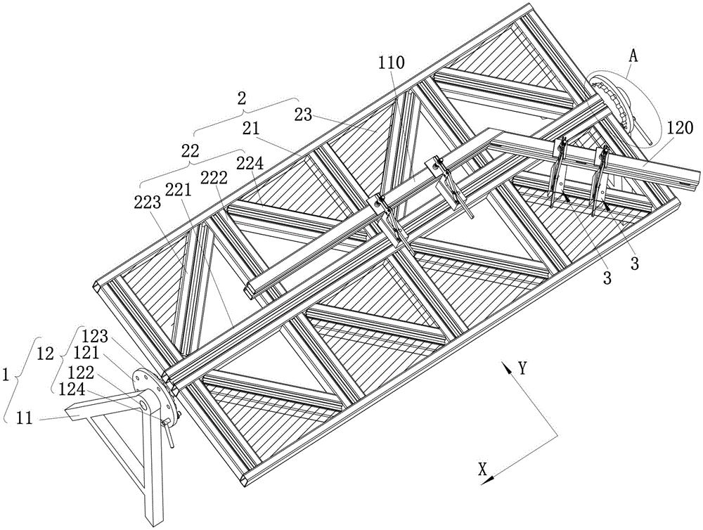
The embodiment provides a fixing device for fixing a workpiece to be machined so as to assist a worker in finishing machining. As shown in fig. 1, the fixing apparatus includes a support base 1, a table 2, and a stopper 3. The workbench 2 is arranged on the supporting seat 1, so that the workbench 2 is positioned at a proper height, and the operation of workers is facilitated. The workpiece to be processed is placed on the workbench 2, and the limiting device 3 is used for positioning the workpiece to be processed so as to improve the processing precision.
To facilitate positioning of the workpiece to be machined, the table 2 includes a slide rail assembly 22, the slide rail assembly 22 is capable of supporting the workpiece to be machined, and the slide rail assembly 22 includes a plurality of slide rails extending in at least two directions. The stopper device 3 can be selectively mounted on any one of a plurality of slide rails, and the stopper device 3 is configured to be able to make a workpiece to be processed parallel to the slide rail on which the stopper device 3 is mounted. Through the cooperation of the slide rail and the limiting device 3, the positioning difficulty of the workpiece to be processed can be reduced, and the positioning precision of the workpiece to be processed is improved, so that the processing quality is improved, the adjustment work is reduced, and the stability of the processing quality is ensured.
For convenience of description, the workpiece to be processed in this embodiment may be a reinforcing system product installed outside the aluminum template, specifically, may be a reinforcing pipe, and correspondingly, the processing technology is a welding technology. As shown in fig. 1, the reinforcing system product installed outside the aluminum formwork includes a first reinforcing pipe 110 and a second reinforcing pipe 120, and the first reinforcing pipe 110 and the second reinforcing pipe 120 are welded and fixed when the mold is assembled. According to different reinforcement requirements and template structures, included angles of the first reinforcement pipe 110 and the second reinforcement pipe 120 during welding are different, and in the prior art, the first reinforcement pipe 110 and the second reinforcement pipe 120 are welded after the angles are generally debugged by workers on site, so that the problems of complex position debugging, inaccurate precision and unstable welding quality exist.
In order to solve the above problem, in the embodiment, the slide rails in the slide rail assembly 22 have at least two extending directions, according to welding requirements, two suitable slide rails may be selected, so that an included angle between the two slide rails is the same as a target included angle of the first reinforcing tube 110 and the second reinforcing tube 120 after welding, and then the limiting device 3 is installed on the two selected slide rails, so that the first reinforcing tube 110 and the second reinforcing tube 120 can be parallel to the two slide rails, respectively, to assist in completing the positioning of the first reinforcing tube 110 and the second reinforcing tube 120. The fixing equipment in the embodiment can reduce the dependence degree of workpiece positioning on the labor skills of workers, the workpiece positioning is more convenient, the debugging process can be simplified, the workpiece positioning precision is improved, and the stability of the welding quality is favorably ensured.
Specifically, the plurality of slide rails in the table 2 have four extending directions in total. The first slide rail 221 extends along the X direction, the second slide rail 222 extends along the Y direction, and the third slide rail 223 and the fourth slide rail 224 are respectively disposed at an included angle with the X direction and the Y direction, and the X direction is perpendicular to the Y direction.
Exemplarily, the limiting device 3 is mounted on the first sliding rail 221 and the fourth sliding rail 224, respectively. The limiting device 3 on the first sliding rail 221 is used for positioning the first reinforcing pipe 110 so that the first reinforcing pipe 110 is parallel to the first sliding rail 221; the limiting device 3 on the fourth slide rail 224 is used for positioning the second reinforcing tube 120, so that the second reinforcing tube 120 is parallel to the fourth slide rail 224, thereby ensuring that the first reinforcing tube 110 and the second reinforcing tube 120 are welded and fixed according to a preset angle.
It should be noted here that the specific extending directions of the third slide rail 223 and the fourth slide rail 224 can be set according to actual needs. The number of the total extending directions of the plurality of slide rails in the slide rail assembly 22 can also be set according to actual needs.
In order to further improve the positioning accuracy of the first reinforcing tube 110 and the second reinforcing tube 120, at least two limiting devices 3 can be mounted on each selected slide rail, so that the first reinforcing tube 110 and the second reinforcing tube 120 respectively have at least two abutting stressed positions, and the extending directions of the first reinforcing tube 110 and the second reinforcing tube 120 are better ensured.
For the stability that improves workstation 2, workstation 2 still includes frame 21, and frame 21 is annular framework, and slide rail set spare 22 sets up in frame 21 and fixed with frame 21 to make workstation 2 form stable structure, improve workstation 2's intensity. Specifically, the frame 21 is rectangular, and the frame 21 may be formed by connecting four rectangular square pipes end to end. The section of the rectangular square pipe is a rectangular and hollow metal section, and the rectangular square pipe has the advantages of light weight, good strength and the like.
In order to enable the fixing device to meet the requirement of processing special-shaped pieces, the workbench 2 further comprises a bedplate 23, and the bedplate 23 is arranged in a space defined by a plurality of slide rails or the bedplate 23 is arranged in a space defined by the slide rail assemblies 22 and the frame 21.
Because of first reinforcement pipe 110 and second reinforcement pipe 120 welding time, the welding seam is the annular, and for convenient welding, workstation 2 can rotate around the X direction relatively supporting seat 1 to weld the opposite side welding seam.
Specifically, the supporting seat 1 includes two frame bodies 11 that are arranged oppositely, the workbench 2 is arranged between the two frame bodies 11, and two ends of the workbench 2 are connected with the frame body 11 on the corresponding side through the rotating mechanism 12 respectively.
As shown in fig. 1 and 2, the rotation mechanism 12 includes a fixed disk 121, a dial 123, a rotation shaft 122, and a locking pin 124. The fixing plate 121 is disposed on the frame 11, the rotating shaft 122 is fixed to the worktable 2, and two ends of the fixing plate are respectively rotatably connected to the fixing plate 121 on the corresponding side. The rotation plate 123 and the rotation shaft 122 are coaxially disposed and fixed, a plurality of locking grooves 1231 are circumferentially disposed on the rotation plate 123, and the locking pin 124 can pass through the fixing plate 121 and be locked in one of the locking grooves 1231, so as to limit the rotation of the rotation plate 123 relative to the fixing plate 121. When the angle of the workbench 2 needs to be adjusted, the locking pin 124 is pulled out, so that the turntable 123 can rotate along with the workbench 2 relative to the frame body 11, and the angle adjustment of the workbench 2 is realized. After the workbench 2 is adjusted to a required angle, the locking pin 124 passes through the rotating disc 123 and is inserted into the locking groove 1231 at a corresponding position, and the rotation of the rotating disc 123 is limited by the matching of the locking pin 124 and the inner wall of the locking groove 1231, so that the angle locking of the workbench 2 is realized.
It can be understood that the angle adjustment precision of the workbench 2 can be increased by reasonably setting the number of the locking grooves 1231, so that the workbench 2 can better meet the requirements of the welding process.
In order to improve the bearing capacity of the slide rail, as shown in fig. 3, the slide rail includes two beam tubes 2211 arranged in parallel and at an interval, and a groove 2212 arranged between the two beam tubes 2211. The beam tube 2211 is used for supporting the reinforcing tube or the limiting device 3, and can avoid deformation of the sliding rail. The slot 2212 is used for sliding fit with the limiting device 3. The two ends of the bottom surface of the limiting device 3 are respectively supported by the two beam tubes 2211, and the middle of the bottom surface of the limiting device 3 is in sliding fit with the groove body 2212, so that the limiting device 3 is more stable, and the improvement of the positioning accuracy of the reinforcing tubes is facilitated.
The beam tube 2211 is a rectangular square tube, the section of the rectangular square tube is a rectangular hollow metal section, and the beam tube has the advantages of light weight, good strength and the like. The groove body 2212 is provided with a T-shaped groove, the T-shaped groove comprises an upper groove section 22121 and a lower groove section 22122, the width of the upper groove section 22121 is smaller than that of the lower groove section 22122, and the limiting device 3 is matched with the T-shaped groove to prevent the limiting device 3 from being separated from the groove body 2212.
As shown in fig. 4, the stopper device 3 includes a base 31, a stopper mechanism 32, and a lock mechanism 33. The base 31 can be slidably coupled to the slot 2212. Limiting mechanism 32 sets up on base member 31, and limiting mechanism 32 can be followed and predetermine horizontal direction and reinforced pipe butt, and wherein, predetermine horizontal direction and perpendicular with the slide rail of installation limiting mechanism 32. When the reinforcing pipes are fixed, the base 31 slides to a proper position along the groove 2212, the base 31 and the slide rails are fixed through the locking mechanism 33, and then the limiting mechanism 32 is matched with the reinforcing pipes, so that the reinforcing pipes are parallel to the corresponding slide rails.
For further improving the stability after the reinforcing pipe location, stop device 3 still includes hold-down mechanism 34, and hold-down mechanism 34 can compress tightly the reinforcing pipe from top to bottom to avoid reinforcing pipe position to take place to remove in welding process. In addition, stress is generated after the reinforcing pipe is welded, and the pressing mechanism 34 can also prevent the product angle deformation from exceeding the preset deviation due to the deformation generated by the release of the stress after welding, so that the shape correction workload is reduced.
As shown in fig. 4, the pressing mechanism 34 includes a pressing drive assembly 342 and a ram assembly 341. The pressing driving assembly 342 is disposed on the base 31, and the pressing driving assembly 342 can drive the pressing head assembly 341 to press the reinforcement pipe so as to prevent the reinforcement pipe from moving, or drive the pressing head assembly 341 to be separated from the reinforcement pipe so as to take out the welded product.
To further facilitate the operation of the worker, the pressing driving assembly 342 can achieve rapid pressing of the reinforcement pipe. Specifically, the compression drive assembly 342 includes a mount 3421, a mount 3422, a linkage structure 3423, and a wrench 3424. The fixing mount 3421 is disposed on the base 31. The mounting block 3422 is hinged to the mounting block 3421, and the pressing head assembly 341 is disposed on the mounting block 3422. One end of the link structure 3423 is hinged to the fixing frame 3421, and the other end is hinged to the mounting frame 3422. The wrench 3424 is connected to the link structure 3423 and can drive the link structure 3423 to be at or separated from the dead point position. When the reinforcing tube needs to be compressed, the wrench 3424 is rotated to make the wrench 3424 drive the connecting rod structure 3423 to rotate to the dead point position, and the connecting rod structure 3423 is locked, so that the angle of the mounting rack 3422 relative to the fixing rack 3421 is fixed, and the pressure head assembly 341 is kept at the position where the reinforcing tube is compressed to continuously provide the compression force to the reinforcing tube. When the reinforcing tube needs to be taken out, the wrench 3424 is reversely pulled, and the wrench 3424 drives the connecting rod structure 3423 to release the locking state, so that the mounting rack 3422 can rotate relative to the fixing rack 3421 to drive the pressing head assembly 341 to separate from the reinforcing tube.
Specifically, the link structure 3423 includes a first link 34231 and a second link 34232. One end of the first link 34231 is hinged to the fixing frame 3421, the other end of the first link 34231 is hinged to one end of the second link 34232, and the other end of the second link 34232 is hinged to the mounting frame 3422. When the link structure 3423 is at the dead point position, the first link 34231 and the second link 34232 are collinear. The wrench 3424, the first connecting rod and the second connecting rod are rotatably connected by a pivot shaft, so as to simplify the structure of the pressing driving assembly 342. The first connecting rod and the fixing frame 3421, the second connecting rod and the mounting frame 3422, and the mounting frame 3422 and the fixing frame 3421 are rotatably connected by a pivot shaft, respectively.
Optionally, the mounting block 3422 includes two opposite mounting plates, which are respectively located at two opposite sides of the fixing frame 3421 and are rotatably connected to the fixing frame 3421 to improve the stability of the mounting block 3422.
Alternatively, the fixing frame 3421 is L-shaped, the first link 34231 is connected to one end of the fixing frame 3421, and the other end of the second link 34232 is connected to the other end of the fixing frame 3421. When the connecting rod structure 3423 is located at the dead point, the connecting rod structure 3423 and the fixing frame 3421 form a triangle, which is beneficial to improving the stability of the connecting rod structure 3423 at the dead point.
When the fixed pipe needs to be compressed, a worker can press the fixed pipe quickly by pulling the wrench 3424, but since different sizes of the reinforcing pipes may be different, in order to accommodate the reinforcing pipes with different sizes and ensure the compression effect, the pressing head assembly 341 includes a compression adjusting rod 3411 and a pressing plate 3412. The upper end of the pressing adjusting rod 3411 is in threaded connection with the pressing driving assembly 342, the lower end of the pressing adjusting rod 3411 is rotatably connected with a pressing plate 3412, and the pressing plate 3412 is used for being abutted to a workpiece to be machined. By screwing the pressing adjusting rod 3411 with the pressing driving assembly 342, the height of the pressing plate 3412 when the connecting rod structure 3423 is located at the dead point position can be adjusted, so that the pressing plate 3412 is ensured to be in good abutting connection with the reinforcing pipe, and the pressing effect on the reinforcing pipe is improved.
In order to fix the base 31 at any position of the slide rail according to the use requirement, the locking mechanism 33 includes a locking adjustment lever 331, a locking chuck 332, and a locking block 333. The bottom end of the locking adjustment lever 331 is connected with a locking block 333, and the locking adjustment lever 331 is connected with the base 31 and can move in the vertical direction relative to the base 31 and rotate around the axis of the locking adjustment lever 331. The width of the lock block 333 is less than the width of the upper slot segment 22121 and the length of the lock block 333 is greater than the width of the upper slot segment 22121 and less than the width of the lower slot segment 22122. The lock chuck 332 is movably coupled to the base 31 to be switched between a first position and a second position. When the locking chuck 332 is located at the first position, the locking adjustment lever 331 is movable in a vertical direction with respect to the base 31, and when the locking chuck 332 is located at the second position, the positions of the locking adjustment lever 331 and the base 31 in the vertical direction are fixed.
Specifically, the base 31 is provided with a first insertion hole 312 and a second insertion hole 311, and the first insertion hole 312 and the second insertion hole 311 intersect. The locking adjustment rod 331 is inserted into the first insertion hole 312, and the locking chuck 332 can be inserted into the second insertion hole 311 with an adjustable insertion depth, so that the locking chuck 332 can be switched between a first position and a second position. The locking adjustment rod 331 and the locking chuck 332 are inserted into and engaged with the base 31, so that the structure can be more compact, and the first insertion hole 312 and the second insertion hole 311 can respectively guide the locking adjustment rod 331 and the locking chuck 332.
Alternatively, two or more first insertion holes 312 and two or more second insertion holes 311 may be provided, the plurality of first insertion holes 312 are arranged in a predetermined horizontal direction, and each first insertion hole 312 is provided with one second insertion hole 311 communicating therewith. When the limiting device 3 is engaged with the slide rail, the locking adjusting rod 331 can be assembled in the suitable first inserting hole 312 according to actual requirements to adjust the relative position of the base 31 and the slide rail, and further adjust the distance between the reinforcing pipe abutted against the limiting mechanism 32 and the slide rail.
As shown in fig. 5, when the position of the base 31 on the slide rail needs to be adjusted, the lock chuck 332 is adjusted to the first position, and the lock adjustment lever 331 is rotated so that the longitudinal direction of the lock block 333 is parallel to the longitudinal direction of the slot 2212. The lock adjustment lever 331 is actuated to move downward relative to the base 31 such that the lock block 333 passes through the upper slot section 22121 and into the lower slot section 22122. After the base 31 is adjusted to a required position, as shown in fig. 6, the locking adjusting rod 331 is rotated to make the length direction of the locking block 333 perpendicular to the slot 2212, and the locking block 333 cannot be separated from the slot 2212 under the limiting action of the top inner wall of the T-shaped slot. The adjustment lock adjustment lever 331 moves upward relative to the base 31 so that the lock block 333 abuts against the top inner wall of the T-shaped groove to restrict the base 31 from sliding relative to the groove 2212. Finally, the locking chuck 332 is moved to the second position to lock the position of the locking adjustment lever 331 with the base 31 in the vertical direction.
As shown in fig. 7, the locking chuck 332 can be sleeved on the locking adjustment rod 331, the locking chuck 332 is provided with a first adjustment through hole 3321 and a second adjustment through hole 3322, and the first adjustment through hole 3321 is communicated with the second adjustment through hole 3322. At least two first position-limiting flanges 33121 are spaced apart from each other on the locking adjustment lever 331, and the at least two first position-limiting flanges 33121 are arranged along the axial direction of the locking adjustment lever 331. Two second limiting flanges 3323 arranged at intervals are arranged on the inner wall of the second adjusting through hole 3322. When the locking chuck 332 is located at the first position, the locking adjustment rod 331 is inserted into the first adjustment through hole 3321, and the locking adjustment rod 331 can rotate in the first adjustment through hole 3321 and can move up and down in the first adjustment through hole 3321. When the lock chuck 332 moves from the first position to the second position, the lock adjustment rod 331 can enter the second adjustment through hole 3322 through the first adjustment through hole 3321, one first stopper flange 33121 of the lock adjustment rod 331 is caught between the two second stopper flanges 3323, and the vertical movement of the lock adjustment rod 331 with respect to the base 31 is restricted by the clamping action of the two second stopper flanges 3323.
As shown in fig. 6 and 8, the locking adjustment rod 331 includes a locking screw 3311 and a shaped nut 3312, the locking block 333 is connected to the bottom end of the locking screw 3311, the shaped nut 3312 is threadedly connected to the locking screw 3311, and the first position-limiting flange 33121 is disposed on the shaped nut 3312. The locking adjusting rod 331 with the structure has simple structure and convenient processing and assembly. In other embodiments, the locking adjustment lever 331 can be an integrally formed structure to reduce the number of parts of the fastening device.
As shown in fig. 9, the limiting mechanism 32 includes an abutting plate 321, and the abutting plate 321 is vertically arranged and parallel to a slide rail on which the limiting device 3 is mounted. The side surfaces of the reinforcing pipes are completely attached to the abutting plates 321, so that the reinforcing pipes are parallel to the corresponding sliding rails, and the positioning of the reinforcing pipes is realized.
For the convenience of the first reinforcing pipe 110 and the second reinforcing pipe 120 matching, the limiting mechanism 32 further comprises an adjusting assembly, the adjusting assembly is arranged on the base body 31, and the adjusting assembly is used for adjusting the distance between the abutting plate 321 and the base body 31 along the preset horizontal direction, so that the positions of the first reinforcing pipe 110 and the second reinforcing pipe 120 can be conveniently adjusted in a matching manner, and the accurate butt joint of the welding positions of the first reinforcing pipe 110 and the second reinforcing pipe 120 is ensured.
In this embodiment, the adjustment assembly includes an abutment adjustment lever 322 and an abutment chuck 323. The contact adjustment lever 322 is connected to the base 31 and is movable in a predetermined horizontal direction with respect to the base 31, and the contact plate 321 is provided at one end of the contact adjustment lever 322. The abutment chuck 323 is provided on the base 31 and is switchable between a locked position and an unlocked position. When the abutting chuck 323 is located at the unlocking position, the abutting adjusting rod 322 can move along the preset horizontal direction relative to the base body 31 so as to adjust the position of the abutting plate 321 and ensure that the abutting plate 321 abuts against the reinforcing pipe. When the abutting chuck 323 is located at the locking position, the abutting chuck 323 can lock the position of the abutting adjustment rod 322 and the base 31 along the preset horizontal direction, so as to prevent the abutting plate 321 from moving, and to ensure that the abutting plate 321 is maintained at the required position.
Here, when it is necessary to describe, the structure of the abutting adjustment lever 322 is the same as that of the locking adjustment lever 331, the structure of the abutting chuck 323 is the same as that of the locking chuck 332, and the principle of the engagement between the abutting adjustment lever 322 and the abutting chuck 323 can be referred to the description of the locking adjustment lever 331 and the locking chuck 332, and will not be described again here.
In order to avoid the base 31 from shaking along the preset horizontal direction when being locked with the sliding rail, the bottom of the base 31 is further provided with a sliding block 313, the sliding block 313 can slide in the upper groove section 22121, and the width of the sliding block 313 is matched with the width of the upper groove section 22121, so that the sliding block 313 and the upper groove section 22121 can be matched to realize the positioning of the base 31, and the base 31 is prevented from moving along the preset horizontal direction.
It should be understood that the above-described embodiments of the present invention are merely examples for clearly illustrating the present invention, and are not intended to limit the embodiments of the present invention. Numerous obvious variations, adaptations and substitutions will occur to those skilled in the art without departing from the scope of the utility model. And are neither required nor exhaustive of all embodiments. Any modification, equivalent replacement, and improvement made within the spirit and principle of the present invention should be included in the protection scope of the claims of the present invention.