CN113991187A - Cylinder lithium battery module assembly line - Google Patents
Cylinder lithium battery module assembly line Download PDFInfo
- Publication number
- CN113991187A CN113991187A CN202111637115.8A CN202111637115A CN113991187A CN 113991187 A CN113991187 A CN 113991187A CN 202111637115 A CN202111637115 A CN 202111637115A CN 113991187 A CN113991187 A CN 113991187A
- Authority
- CN
- China
- Prior art keywords
- turnover
- jig
- spot welding
- highland barley
- lithium battery
- Prior art date
- Legal status (The legal status is an assumption and is not a legal conclusion. Google has not performed a legal analysis and makes no representation as to the accuracy of the status listed.)
- Pending
Links
Images


Classifications
-
- H—ELECTRICITY
- H01—ELECTRIC ELEMENTS
- H01M—PROCESSES OR MEANS, e.g. BATTERIES, FOR THE DIRECT CONVERSION OF CHEMICAL ENERGY INTO ELECTRICAL ENERGY
- H01M10/00—Secondary cells; Manufacture thereof
- H01M10/05—Accumulators with non-aqueous electrolyte
- H01M10/058—Construction or manufacture
-
- H—ELECTRICITY
- H01—ELECTRIC ELEMENTS
- H01M—PROCESSES OR MEANS, e.g. BATTERIES, FOR THE DIRECT CONVERSION OF CHEMICAL ENERGY INTO ELECTRICAL ENERGY
- H01M10/00—Secondary cells; Manufacture thereof
- H01M10/04—Construction or manufacture in general
- H01M10/0404—Machines for assembling batteries
-
- H—ELECTRICITY
- H01—ELECTRIC ELEMENTS
- H01M—PROCESSES OR MEANS, e.g. BATTERIES, FOR THE DIRECT CONVERSION OF CHEMICAL ENERGY INTO ELECTRICAL ENERGY
- H01M10/00—Secondary cells; Manufacture thereof
- H01M10/04—Construction or manufacture in general
- H01M10/0422—Cells or battery with cylindrical casing
-
- H—ELECTRICITY
- H01—ELECTRIC ELEMENTS
- H01M—PROCESSES OR MEANS, e.g. BATTERIES, FOR THE DIRECT CONVERSION OF CHEMICAL ENERGY INTO ELECTRICAL ENERGY
- H01M10/00—Secondary cells; Manufacture thereof
- H01M10/05—Accumulators with non-aqueous electrolyte
- H01M10/052—Li-accumulators
-
- H—ELECTRICITY
- H01—ELECTRIC ELEMENTS
- H01M—PROCESSES OR MEANS, e.g. BATTERIES, FOR THE DIRECT CONVERSION OF CHEMICAL ENERGY INTO ELECTRICAL ENERGY
- H01M50/00—Constructional details or processes of manufacture of the non-active parts of electrochemical cells other than fuel cells, e.g. hybrid cells
- H01M50/20—Mountings; Secondary casings or frames; Racks, modules or packs; Suspension devices; Shock absorbers; Transport or carrying devices; Holders
- H01M50/204—Racks, modules or packs for multiple batteries or multiple cells
- H01M50/207—Racks, modules or packs for multiple batteries or multiple cells characterised by their shape
- H01M50/213—Racks, modules or packs for multiple batteries or multiple cells characterised by their shape adapted for cells having curved cross-section, e.g. round or elliptic
-
- H—ELECTRICITY
- H01—ELECTRIC ELEMENTS
- H01M—PROCESSES OR MEANS, e.g. BATTERIES, FOR THE DIRECT CONVERSION OF CHEMICAL ENERGY INTO ELECTRICAL ENERGY
- H01M50/00—Constructional details or processes of manufacture of the non-active parts of electrochemical cells other than fuel cells, e.g. hybrid cells
- H01M50/20—Mountings; Secondary casings or frames; Racks, modules or packs; Suspension devices; Shock absorbers; Transport or carrying devices; Holders
- H01M50/258—Modular batteries; Casings provided with means for assembling
-
- H—ELECTRICITY
- H01—ELECTRIC ELEMENTS
- H01M—PROCESSES OR MEANS, e.g. BATTERIES, FOR THE DIRECT CONVERSION OF CHEMICAL ENERGY INTO ELECTRICAL ENERGY
- H01M6/00—Primary cells; Manufacture thereof
- H01M6/005—Devices for making primary cells
-
- Y—GENERAL TAGGING OF NEW TECHNOLOGICAL DEVELOPMENTS; GENERAL TAGGING OF CROSS-SECTIONAL TECHNOLOGIES SPANNING OVER SEVERAL SECTIONS OF THE IPC; TECHNICAL SUBJECTS COVERED BY FORMER USPC CROSS-REFERENCE ART COLLECTIONS [XRACs] AND DIGESTS
- Y02—TECHNOLOGIES OR APPLICATIONS FOR MITIGATION OR ADAPTATION AGAINST CLIMATE CHANGE
- Y02E—REDUCTION OF GREENHOUSE GAS [GHG] EMISSIONS, RELATED TO ENERGY GENERATION, TRANSMISSION OR DISTRIBUTION
- Y02E60/00—Enabling technologies; Technologies with a potential or indirect contribution to GHG emissions mitigation
- Y02E60/10—Energy storage using batteries
-
- Y—GENERAL TAGGING OF NEW TECHNOLOGICAL DEVELOPMENTS; GENERAL TAGGING OF CROSS-SECTIONAL TECHNOLOGIES SPANNING OVER SEVERAL SECTIONS OF THE IPC; TECHNICAL SUBJECTS COVERED BY FORMER USPC CROSS-REFERENCE ART COLLECTIONS [XRACs] AND DIGESTS
- Y02—TECHNOLOGIES OR APPLICATIONS FOR MITIGATION OR ADAPTATION AGAINST CLIMATE CHANGE
- Y02P—CLIMATE CHANGE MITIGATION TECHNOLOGIES IN THE PRODUCTION OR PROCESSING OF GOODS
- Y02P70/00—Climate change mitigation technologies in the production process for final industrial or consumer products
- Y02P70/50—Manufacturing or production processes characterised by the final manufactured product
Landscapes
- Chemical & Material Sciences (AREA)
- Chemical Kinetics & Catalysis (AREA)
- Electrochemistry (AREA)
- General Chemical & Material Sciences (AREA)
- Engineering & Computer Science (AREA)
- Manufacturing & Machinery (AREA)
- Battery Mounting, Suspending (AREA)
- Sealing Battery Cases Or Jackets (AREA)
Abstract
The invention relates to an assembly production line of a cylindrical lithium battery module, which comprises a battery cell sorting device for sorting battery cells, a battery cell support device for inserting the battery cells into a lower support, a polarity inspection device for detecting the positive and negative poles of the battery cells, a jig cover closing device for buckling the upper support and the lower support, a spot welding device A for welding one side of a product, a turnover device for turning over the product, a spot welding device B for welding the other side of the product and a product blanking device. The invention provides a cylindrical lithium battery module assembly production line, which adopts a whole-line automatic solution, reduces manual intervention operation stations, realizes higher automation degree of battery pack assembly, effectively improves production efficiency, reduces labor cost and improves enterprise competitiveness.
Description
Technical Field
The invention relates to the field of lithium battery assembly production, in particular to a cylindrical lithium battery module assembly production line.
Background
The production of lithium cell has followed traditional manual work, updates gradually to machine-building, nevertheless discovers in actual production, and the machine-building production of lithium cell still has more station and needs the manual intervention operation, need produce through artifical and mechanical cooperation mode in coordination, and the manual operation station is more, and the operating personnel operation degree of difficulty is high, and personnel's input is great, and the production efficiency of lithium cell still exists the promotion space.
Disclosure of Invention
In view of this, the invention provides an assembly production line of cylindrical lithium battery modules, which is a whole-line automatic solution, reduces manual intervention operation stations, realizes higher automation degree of battery pack assembly, effectively improves production efficiency, reduces labor cost, and improves enterprise competitiveness.
The purpose of the invention is realized by the following technical scheme:
the utility model provides a cylinder lithium cell module assembly line, is including the electric core sorting facilities that is used for selecting separately electric core, insert electric core on the lower carriage with electric core and go into support equipment, be used for detecting the positive negative polarity check out test set of electric core, be used for with upper bracket and lower carriage close the tool of lid lock close cover equipment, spot welding equipment A of welding product one side, the tipping arrangement of upset product, spot welding equipment B of welding product opposite side and product unloading equipment.
Preferably, the battery cell sorting equipment comprises a battery cell sorting conveyer belt, a power taking core mechanism, a highland barley paper pasting mechanism, a code scanner, a testing machine, a battery cell grading mechanism and a lifting storage bin, wherein the power taking core mechanism, the highland barley paper pasting mechanism, the code scanner, the testing machine, the battery cell grading mechanism and the lifting storage bin are sequentially distributed along the battery cell sorting conveyer belt.
Preferably, the electricity taking core mechanism comprises an electricity taking frame, a first material taking shaft arranged on the electricity taking frame, a second material taking shaft arranged on the first material taking shaft, and an electricity taking device arranged on the second material taking shaft.
Preferably, the highland barley paper pasting mechanism comprises a movable highland barley paper material belt connected with the cell sorting conveyor belt, a highland barley paper pushing cylinder for driving the movable highland barley paper material belt to move, a highland barley paper feeding tray located beside the movable highland barley paper material belt, a highland barley paper cutting device, a highland barley paper waste collection box and a highland barley paper collecting tray.
Preferably, the battery cell support entering device comprises a feeding mechanical arm for taking materials from the lifting storage bin, a code scanning mechanism, a battery cell entering mechanism for loading the battery cell into the lower support and a discharging mechanical arm; the polarity check equipment comprises a plane transplanting mechanism and a polarity check mechanism.
Preferably, the jig cover closing device comprises a turnover cover closing mechanism, a support operator station, a first operation speed doubling chain and a first jig backflow speed doubling chain, wherein the turnover cover closing mechanism comprises a turnover seat, a turnover guide rail arranged on the turnover seat, a turnover frame moving along the turnover guide rail, a turnover lifting cylinder arranged on the turnover frame, a turnover inner support driven by the turnover lifting cylinder, a first clamping arm, a second clamping arm and a clamping cylinder arranged on the turnover inner support, and the first clamping arm and the second clamping arm respectively abut against two end parts of the jig so as to clamp the jig.
Preferably, the spot welding equipment A comprises a first spot welding mechanism, a second operation speed multiplying chain, a second jig backflow speed multiplying chain and a first spot welding power supply.
Preferably, the turnover equipment comprises a turnover mechanism, a third operation speed-multiplying chain and a third jig backflow speed-multiplying chain, wherein the turnover mechanism comprises a turnover base, a turnover slide rail arranged on the turnover base, a turnover displacement cylinder arranged on the turnover base, a turnover side bracket driven by the turnover displacement cylinder, a first clamping arm, a second clamping arm and a clamping cylinder arranged on the turnover side bracket, and the first clamping arm and the second clamping arm respectively prop against two end parts of the jig to clamp the jig.
Preferably, the spot welding equipment B comprises a second spot welding mechanism, a fourth operation speed multiplying chain, a fourth jig backflow speed multiplying chain and a second spot welding power supply.
Preferably, the product blanking equipment comprises a cover opening blanking mechanism, a transplanting mechanism, a fifth operation speed multiplying chain and a fifth jig backflow speed multiplying chain, wherein the cover opening blanking mechanism comprises a clamp for clamping an upper cover of a jig and an upper cylinder and a lower cylinder for driving the clamp to move up and down.
Compared with the prior art, the invention has the beneficial effects that:
according to the cylindrical lithium battery module assembly production line, the whole-line automatic solution is adopted, so that the number of operation stations for manual intervention is reduced, the higher automation degree of battery pack assembly is realized, the production efficiency is effectively improved, the labor cost is reduced, and the enterprise competitiveness is improved. Electric core sorting equipment, polarity check out test set, spot welding equipment, tipping arrangement, product unloading equipment have all realized full automated production, need not artifical the intervention, full automation production, and independent each other between the equipment, link up through material assembly line and manipulator, during the production line upgrade, only need the replacement correspond equipment can, need not to rebuild whole production line. The battery core entering support equipment and the jig cover closing equipment still need manual intervention, but the working content is simpler and easier. Specifically, in the equipment for placing the battery cell into the bracket, an operator only needs to put the product lower bracket into a bracket positioning jig of the battery cell mechanism; in the jig cover closing device, an operator buckles the upper bracket on the lower bracket. The manual operation has few stations and high automation degree, and improves the production efficiency.
Drawings
Fig. 1 is a schematic diagram of a whole line layout of an assembly production line of a cylindrical lithium battery module according to an embodiment of the present invention.
Fig. 2 is a structural diagram of the cell sorting apparatus according to an embodiment of the present invention.
Fig. 3 is a structural diagram of a core taking mechanism according to an embodiment of the present invention.
Fig. 4 is a structural diagram of a highland barley paper attaching mechanism in an embodiment of the invention.
FIG. 5 is a block diagram of a code scanner according to an embodiment of the present invention.
FIG. 6 is a block diagram of a tester according to an embodiment of the invention.
Fig. 7 is a structural diagram of a cell stepping mechanism according to an embodiment of the present invention.
Fig. 8 is a structural diagram of the lifting storage bin in an embodiment of the invention.
Fig. 9 is a structural diagram of a battery electrical-core support device in an embodiment of the present invention.
FIG. 10 is a block diagram of a code scanning mechanism according to an embodiment of the present invention.
Fig. 11 is a structural diagram of a polarity check apparatus according to an embodiment of the present invention.
Fig. 12 is a structural view of a planar transplanting mechanism according to an embodiment of the present invention.
Fig. 13 is a structural diagram of a polarity check mechanism in an embodiment of the invention.
Fig. 14 is a structural diagram of a fixture cover closing apparatus according to an embodiment of the present invention.
Fig. 15 is a structural diagram of a flip cover closing mechanism according to an embodiment of the present invention.
Fig. 16 is a structural view of a spot welding apparatus a in one embodiment of the present invention.
Fig. 17 is a structural view of a first spot welding mechanism in an embodiment of the present invention.
Fig. 18 is a structural diagram of the flipping apparatus in an embodiment of the present invention.
FIG. 19 is a block diagram of a canting mechanism in an embodiment of the invention.
Fig. 20 is a structural view of a spot welding apparatus B in an embodiment of the present invention.
Fig. 21 is a structural diagram of a second spot welding mechanism in an embodiment of the present invention.
Fig. 22 is a structural diagram of a product blanking apparatus in an embodiment of the present invention.
Fig. 23 is a structural view of a lid opening and blanking mechanism in an embodiment of the invention.
Fig. 24 is a structural view of a transplanting mechanism in an embodiment of the present invention.
Detailed Description
To facilitate understanding of those skilled in the art, the present invention will be described in further detail below with reference to specific embodiments and the accompanying drawings.
Referring to fig. 1-24, an embodiment of the invention includes:
the technical whole line layout of the invention is schematically shown in the attached figure 1, and comprises the following devices: the battery core sorting device comprises a battery core sorting device 100 for sorting battery cores, a battery core entering support device 200 for inserting the battery cores into a lower support, a polarity checking device 300 for detecting the positive and negative poles of the battery cores, a jig cover closing device 400 for closing the upper support and the lower support, a spot welding device A500 for welding one side of a product, a turnover device 600 for turning the product, a spot welding device B700 for welding the other side of the product, and a product blanking device 800.
As shown in fig. 2, the battery cell sorting apparatus 100 includes a battery cell sorting conveyer 110, a battery core taking mechanism 120 sequentially distributed along the battery cell sorting conveyer 110, a highland barley paper attaching mechanism 130 for attaching highland barley paper to the positive electrode of the battery cell, a code scanner 140, a testing machine 150, a battery cell grading mechanism 160 linked with the testing machine, and a lifting storage bin 170. The core taking mechanism 120 comprises a material taking frame 121, a material taking shaft I122 arranged on the material taking frame 121, a material taking shaft II 123 arranged on the material taking shaft I122, and a material taking device 124 arranged on the material taking shaft II 123. The highland barley paper pasting mechanism 130 comprises a movable highland barley paper material belt 131 connected with the cell sorting conveyer belt, a highland barley paper pushing cylinder 132 for driving the movable highland barley paper material belt to move, a highland barley paper discharging tray 133 positioned beside the movable highland barley paper material belt, a highland barley paper cutter 134, a highland barley paper waste collection box 135 and a highland barley paper collection tray 136.
Like figure 3, the carton electricity core is stored to the belt line, realizes electric core automatic feeding, and the tripper extracts electric core and puts on electric core selects separately the conveyer belt.
As shown in fig. 4-6, the cells are sequentially arranged on the belt line, and the positive pole highland barley paper pasting, the cell code scanning and the cell testing are sequentially completed.
As shown in fig. 7-8, the electric core grading mechanism sequentially puts the electric cores into the corresponding grouping channels according to the test results of the electric cores, and the electric core storage in the grouping channels adopts a lifting type stock bin mode, so that 200 electric cores can be stored in a single channel.
Referring to fig. 9, the electrical core loading frame apparatus 200 includes a loading robot 210 for taking materials from the lifting storage bin, a code scanning mechanism 220, an electrical core loading mechanism 230 for loading electrical cores into the lower frame, and an unloading robot 240.
As shown in fig. 10, the feeding manipulator sucks the electric core from the lifting type storage bin and finishes the electric core group code scanning in the code scanning mechanism. And the operator puts the product lower bracket into a bracket positioning jig of the electric core mechanism, and the electric core mechanism loads the electric cores into the bracket one by one. And the blanking manipulator clamps and places the support of the battery cell into the lower spot welding jig, and then the next operation is carried out.
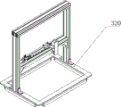
As shown in fig. 11, the polarity inspection apparatus 300 includes a planar transplanting mechanism 310 and a polarity inspection mechanism 320.
As shown in fig. 12-13, the feeding manipulator transports the inserted cell support to a lower spot welding jig, the planar transplanting mechanism transports the jig to the lower part of the polarity checking mechanism, and the equipment starting camera checks whether the polarity of the product cell meets the process requirements; and (4) polarity check OK, wherein the jig flows into the next work station, polarity check NG is carried out, the jig is moved to one side, and equipment alarms prompt manual processing.
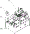
Referring to fig. 14, the jig cover closing apparatus 400 includes a flip cover closing mechanism 410, a cover support operator station 420, a first operation speed multiplication chain 430, and a first jig backflow speed multiplication chain 440, where the flip cover closing mechanism 410 includes a flip base 411, a flip guide 412 disposed on the flip base, a flip frame 413 moving along the flip guide, a flip lifting cylinder 414 mounted on the flip frame, a flip inner support 415 driven by the flip lifting cylinder, a first clamping arm 416 mounted on the flip inner support, a second clamping arm 417, and a clamping cylinder 418, and the first clamping arm and the second clamping arm respectively abut against two ends of the jig to clamp the jig.
As shown in fig. 15, the product of the polarity check OK is conveyed to a manual operation position along with the jig, the mechanism is jacked up for positioning, and the operator buckles the upper bracket on the lower bracket to complete the installation of the upper bracket; the product loaded with the upper support is conveyed to a cover closing station along with the jig, the mechanism is jacked up for positioning, the overturning cover closing mechanism automatically clamps the upper spot welding jig from the opposite double-speed chain, the overturning mechanism is moved and overturned, the upper spot welding jig and the lower spot welding jig are buckled together to form a complete spot welding jig, and the spot welding jig after being combined is conveyed to the next procedure.
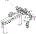
Referring to fig. 16, the spot welding apparatus a500 includes a first spot welding mechanism 510, a second operation speed multiplying chain 520, a second jig reflow speed multiplying chain 530, and a first spot welding power source 540.
As shown in fig. 17, the spot welding jig conveyed in the previous step is jacked up and positioned at the spot welding station; the spot welding mechanism is set according to a program and completes welding of all the battery cores on the single surface of the product in two stations; and (5) conveying the jig to the next station after spot welding.
As shown in fig. 18, the turnover device 600 includes a turnover mechanism 610, a third operation speed-multiplying chain 620, and a third jig backflow speed-multiplying chain 630, the turnover mechanism includes a turnover base 611, a turnover slide rail 612 disposed on the turnover base, a turnover displacement cylinder 613 mounted on the turnover base, a turnover side bracket 614 driven by the turnover displacement cylinder, a first clamping arm 615, a second clamping arm 616, and a clamping cylinder 617 mounted on the turnover side bracket, and the first clamping arm and the second clamping arm respectively abut against two ends of the jig to clamp the jig.
As shown in figure 19, the jig after the operation is finished in the previous process is conveyed to a turnover station, and the mechanism is jacked up for positioning; and the overturning mechanism clamps the spot welding jig, the space is overturned for 180 degrees, the surface of the non-spot welding battery core faces upwards, and the jig is conveyed to the next work station after the completion.
Referring to fig. 20, a spot welding apparatus B700 includes a second spot welding mechanism 710, a fourth operation speed multiplication chain 720, a fourth jig reflow speed multiplication chain 730, and a second spot welding power source 740.
As shown in fig. 21, the spot welding jig conveyed in the previous step is jacked up and positioned at the spot welding station; the spot welding mechanism is set according to a program and completes welding of all the battery cores on the single surface of the product in two stations; and (5) conveying the jig to the next station after spot welding.
Referring to fig. 22, the product blanking apparatus 800 includes a cover opening and blanking mechanism 810, a transplanting mechanism 820, a fifth operation speed multiplication chain 830, and a fifth jig backflow speed multiplication chain 840, where the cover opening and blanking mechanism includes a clamper 811 for clamping the upper cover of the jig, and an up-down cylinder 812 for driving the clamper to move up and down.
As shown in the attached figures 23-24, the products after spot welding are conveyed to a blanking and transplanting mechanism; the cover opening and blanking mechanism firstly clamps the jig on the product to be opened, the cover opening and blanking mechanism moves to move the blanking clamp to the product, the blanking clamp moves downwards to clamp the product, the transplanting mechanism sends the jig left on the line body to the opposite speed multiplying chain to be refluxed for repeated use, and meanwhile, the cover opening and blanking mechanism resets to convey the product to a blanking belt line; the jig is turned over by 180 degrees in space and placed into the transplanting mechanism again, and the transplanting mechanism sends the jig to the opposite double-speed chain for backflow reuse.
The present invention is directed to provide an automatic solution for wire harness to solve the problems of the background art, so as to achieve automatic assembly of a battery pack. The technology comprises the processes of single battery cell loading and sorting, highland barley paper pasting, code scanning test, single battery cell entering into a support, support installation, nickel sheet installation, battery cell and nickel sheet spot welding and the like, improves the productivity through an automatic solution, reduces the investment of operators and creates greater value for customers.
In the description of the present invention, it is to be understood that the terms "coaxial", "bottom", "one end", "top", "middle", "other end", "upper", "one side", "top", "inner", "front", "center", "both ends", and the like, indicate orientations or positional relationships based on those shown in the drawings, and are only for convenience of description and simplicity of description, and do not indicate or imply that the referenced device or element must have a particular orientation, be constructed and operated in a particular orientation, and thus, are not to be construed as limiting the present invention.
Furthermore, the terms "first", "second", "third", "fourth" are used for descriptive purposes only and are not to be construed as indicating or implying a relative importance or implicitly indicating the number of technical features indicated, whereby the features defined as "first", "second", "third", "fourth" may explicitly or implicitly include at least one such feature.
In the present invention, unless otherwise expressly specified or limited, the terms "mounted," "disposed," "connected," "secured," "screwed" and the like are to be construed broadly, e.g., as meaning fixedly connected, detachably connected, or integrally formed; can be mechanically or electrically connected; the terms may be directly connected or indirectly connected through an intermediate, and may be communication between two elements or interaction relationship between two elements, unless otherwise specifically limited, and the specific meaning of the terms in the present invention will be understood by those skilled in the art according to specific situations.
Although embodiments of the present invention have been shown and described, it will be appreciated by those skilled in the art that changes, modifications, substitutions and alterations can be made in these embodiments without departing from the principles and spirit of the invention, the scope of which is defined in the appended claims and their equivalents.
Claims (10)
1. The utility model provides a cylinder lithium cell module assembly line, a serial communication port, including electric core sorting facilities (100) that are used for selecting separately electric core, insert electric core on the lower carriage with electric core and go into support equipment (200), polarity check out test set (300) that are used for detecting electric core positive negative pole, a tool that is used for closing upper bracket and lower carriage lid lock closes and covers equipment (400), spot welding equipment A (500) of welding product one side, tipping arrangement (600) of upset product, spot welding equipment B (700) of welding product opposite side, and product unloading equipment (800).
2. The assembly production line of the cylindrical lithium battery module as claimed in claim 1, wherein the battery cell sorting device (100) comprises a battery cell sorting conveyer belt (110), a battery core taking mechanism (120) sequentially distributed along the battery cell sorting conveyer belt (110), a highland barley paper pasting mechanism (130) for pasting highland barley paper on the positive electrode of a battery cell, a code scanner (140), a testing machine (150), a battery cell grading mechanism (160) linked with the testing machine, and a lifting storage bin (170).
3. The assembly production line for the cylindrical lithium battery modules as claimed in claim 2, wherein the core taking mechanism (120) comprises a material taking frame (121), a material taking shaft I (122) arranged on the material taking frame (121), a material taking shaft II (123) arranged on the material taking shaft I (122), and a material taking device (124) arranged on the material taking shaft II (123).
4. The assembly line for cylindrical lithium battery modules as claimed in claim 2, wherein the highland barley paper pasting mechanism (130) comprises a movable highland barley paper tape (131) connected to the cell sorting conveyor, a highland barley paper pushing cylinder (132) for driving the movable highland barley paper tape to move, a highland barley paper placing tray (133) located beside the movable highland barley paper tape, a highland barley paper cutter (134), a highland barley paper waste collecting box (135) and a highland barley paper collecting tray (136).
5. The cylindrical lithium battery module assembly line of claim 1, wherein the cell entering support device (200) comprises a feeding manipulator (210) for taking the cell from the lifting storage bin, a code scanning mechanism (220), a cell entering mechanism (230) for loading the cell into the lower support, and a discharging manipulator (240); the polarity check device (300) comprises a plane transplanting mechanism (310) and a polarity check mechanism (320).
6. The assembly production line of the cylindrical lithium battery module as claimed in claim 1, wherein the jig cover closing device (400) comprises a turnover cover closing mechanism (410), a cover bracket operator station (420), a first operation speed doubling chain (430) and a first jig backflow speed doubling chain (440), the turnover cover closing mechanism (410) comprises a turnover seat (411), a turnover guide rail (412) arranged on the turnover seat, a turnover frame (413) moving along the turnover guide rail, a turnover lifting cylinder (414) arranged on the turnover frame, a turnover inner frame (415) driven by the turnover lifting cylinder, a first clamping arm (416) arranged on the turnover inner frame, a second clamping arm (417) and a clamping cylinder (418), and the first clamping arm and the second clamping arm respectively abut against two ends of the jig so as to clamp the jig.
7. The cylindrical lithium battery module assembly line of claim 1, wherein the spot welding device A (500) comprises a first spot welding mechanism (510), a second operation speed multiplication chain (520), a second jig reflow speed multiplication chain (530), and a first spot welding power supply (540).
8. The cylindrical lithium battery module assembly line of claim 1, wherein the turnover device (600) comprises a turnover mechanism (610), a third operation speed-doubling chain (620) and a third jig return speed-doubling chain (630), the turnover mechanism comprises a turnover base (611), a turnover slide rail (612) arranged on the turnover base, a turnover displacement cylinder (613) arranged on the turnover base, a turnover side bracket (614) driven by the turnover displacement cylinder, and a first clamping arm (615), a second clamping arm (616) and a clamping cylinder (617) arranged on the turnover side bracket, and the first clamping arm and the second clamping arm respectively abut against two ends of a jig so as to clamp the jig.
9. The cylindrical lithium battery module assembly line of claim 1, wherein the spot welding device B (700) comprises a second spot welding mechanism (710), a fourth operation speed multiplication chain (720), a fourth jig reflow speed multiplication chain (730) and a second spot welding power supply (740).
10. The assembly line for cylindrical lithium battery modules as claimed in claim 1, wherein the product blanking device (800) comprises a cover opening and blanking mechanism (810), a transplanting mechanism (820), a fifth operation speed multiplication chain (830) and a fifth jig backflow speed multiplication chain (840), and the cover opening and blanking mechanism comprises a clamper (811) for clamping the upper cover of the jig and an upper and lower cylinder (812) for driving the clamper to move up and down.
Priority Applications (1)
| Application Number | Priority Date | Filing Date | Title |
|---|---|---|---|
| CN202111637115.8A CN113991187A (en) | 2021-12-30 | 2021-12-30 | Cylinder lithium battery module assembly line |
Applications Claiming Priority (1)
| Application Number | Priority Date | Filing Date | Title |
|---|---|---|---|
| CN202111637115.8A CN113991187A (en) | 2021-12-30 | 2021-12-30 | Cylinder lithium battery module assembly line |
Publications (1)
| Publication Number | Publication Date |
|---|---|
| CN113991187A true CN113991187A (en) | 2022-01-28 |
Family
ID=79734924
Family Applications (1)
| Application Number | Title | Priority Date | Filing Date |
|---|---|---|---|
| CN202111637115.8A Pending CN113991187A (en) | 2021-12-30 | 2021-12-30 | Cylinder lithium battery module assembly line |
Country Status (1)
| Country | Link |
|---|---|
| CN (1) | CN113991187A (en) |
Cited By (2)
| Publication number | Priority date | Publication date | Assignee | Title |
|---|---|---|---|---|
| CN116160112A (en) * | 2023-03-16 | 2023-05-26 | 深圳市百耐信科技有限公司 | Laser welding and assembly production line for manufacturing large cylindrical lithium battery |
| CN116454353A (en) * | 2023-03-31 | 2023-07-18 | 苏州天弘激光股份有限公司 | Multi-cell multi-structure modal cell grouping production line and production method thereof |
Citations (7)
| Publication number | Priority date | Publication date | Assignee | Title |
|---|---|---|---|---|
| CN207282634U (en) * | 2017-09-18 | 2018-04-27 | 深圳市深成科技有限公司 | A kind of battery pastes highland barley paper machine |
| CN110649309A (en) * | 2019-10-18 | 2020-01-03 | 深圳市国威科创新能源科技有限公司 | Automatic assembly production line for power battery modules |
| CN210296528U (en) * | 2019-10-11 | 2020-04-10 | 江西迈动智能装备有限公司 | Cam mechanism for cylindrical battery core surface pad |
| CN111613826A (en) * | 2020-05-18 | 2020-09-01 | 惠州市华阳多媒体电子有限公司 | Automatic production line for front section of lithium battery |
| CN111703866A (en) * | 2020-05-18 | 2020-09-25 | 惠州市华阳多媒体电子有限公司 | Multifunctional all-in-one machine |
| CN112366347A (en) * | 2020-12-09 | 2021-02-12 | 广东力科新能源有限公司 | Automatic side device that pastes of battery highland barley paper |
| CN112670590A (en) * | 2021-01-06 | 2021-04-16 | 惠州市华阳多媒体电子有限公司 | 18650 battery package PACK automation line |
-
2021
- 2021-12-30 CN CN202111637115.8A patent/CN113991187A/en active Pending
Patent Citations (7)
| Publication number | Priority date | Publication date | Assignee | Title |
|---|---|---|---|---|
| CN207282634U (en) * | 2017-09-18 | 2018-04-27 | 深圳市深成科技有限公司 | A kind of battery pastes highland barley paper machine |
| CN210296528U (en) * | 2019-10-11 | 2020-04-10 | 江西迈动智能装备有限公司 | Cam mechanism for cylindrical battery core surface pad |
| CN110649309A (en) * | 2019-10-18 | 2020-01-03 | 深圳市国威科创新能源科技有限公司 | Automatic assembly production line for power battery modules |
| CN111613826A (en) * | 2020-05-18 | 2020-09-01 | 惠州市华阳多媒体电子有限公司 | Automatic production line for front section of lithium battery |
| CN111703866A (en) * | 2020-05-18 | 2020-09-25 | 惠州市华阳多媒体电子有限公司 | Multifunctional all-in-one machine |
| CN112366347A (en) * | 2020-12-09 | 2021-02-12 | 广东力科新能源有限公司 | Automatic side device that pastes of battery highland barley paper |
| CN112670590A (en) * | 2021-01-06 | 2021-04-16 | 惠州市华阳多媒体电子有限公司 | 18650 battery package PACK automation line |
Cited By (4)
| Publication number | Priority date | Publication date | Assignee | Title |
|---|---|---|---|---|
| CN116160112A (en) * | 2023-03-16 | 2023-05-26 | 深圳市百耐信科技有限公司 | Laser welding and assembly production line for manufacturing large cylindrical lithium battery |
| CN116160112B (en) * | 2023-03-16 | 2023-10-20 | 深圳市百耐信科技有限公司 | Laser welding and assembly production line for manufacturing large cylindrical lithium battery |
| CN116454353A (en) * | 2023-03-31 | 2023-07-18 | 苏州天弘激光股份有限公司 | Multi-cell multi-structure modal cell grouping production line and production method thereof |
| CN116454353B (en) * | 2023-03-31 | 2024-03-15 | 苏州天弘激光股份有限公司 | Multi-cell multi-structure modal cell grouping production line and production method thereof |
Similar Documents
| Publication | Publication Date | Title |
|---|---|---|
| CN108355989A (en) | A kind of tab cutting for electronic product battery detects mechanism for sorting | |
| CN113991187A (en) | Cylinder lithium battery module assembly line | |
| CN110987629B (en) | Full-automatic tensile test equipment and control system thereof | |
| CN109193303B (en) | USB chip module's equipment mechanism | |
| CN108188714B (en) | Automatic screw locking and laser coding machine | |
| CN111613826A (en) | Automatic production line for front section of lithium battery | |
| CN111299075A (en) | Terminal box plastic equipment | |
| CN111331187A (en) | Battery cell tab cutting device and method | |
| CN210586771U (en) | Multi-axis module full-automatic cell casing machine | |
| CN106542327A (en) | Housing transports upset system and its column type battery container production equipment | |
| CN106563646A (en) | Structure strength detection system and cylindrical-type battery shell body production device including same | |
| CN113458749A (en) | Automatic assembly production line for touch screen | |
| CN212093019U (en) | Terminal box plastic equipment | |
| CN112038679A (en) | Novel automatic lithium battery production line | |
| CN111703866A (en) | Multifunctional all-in-one machine | |
| CN110740608A (en) | automatic installation equipment for PCB (printed circuit board) of small battery pack | |
| CN116779327A (en) | Full-automatic coil bending and welding equipment | |
| CN113829051B (en) | Automatic assembling device and assembling method for intelligent gas meter control box cover | |
| CN113809406B (en) | Flexible production system of power battery pack | |
| CN210745801U (en) | Automatic installation equipment for PCB (printed circuit board) of small battery pack | |
| CN215830901U (en) | Automatic assembly production line for touch screen | |
| CN212197402U (en) | Diversified automatic unloading equipment | |
| CN212197473U (en) | A material loading manipulator for full-automatic tensile test piece | |
| CN114486105A (en) | Multi-station battery cover plate helium detection system | |
| CN209626341U (en) | A kind of cylindrical battery back welding load all-in-one machine |
Legal Events
| Date | Code | Title | Description |
|---|---|---|---|
| PB01 | Publication | ||
| PB01 | Publication | ||
| SE01 | Entry into force of request for substantive examination | ||
| SE01 | Entry into force of request for substantive examination | ||
| RJ01 | Rejection of invention patent application after publication | ||
| RJ01 | Rejection of invention patent application after publication |
Application publication date: 20220128 |