CN113981916A - Energy dissipater for water outlet of thermonuclear power plant - Google Patents
Energy dissipater for water outlet of thermonuclear power plant Download PDFInfo
- Publication number
- CN113981916A CN113981916A CN202111489515.9A CN202111489515A CN113981916A CN 113981916 A CN113981916 A CN 113981916A CN 202111489515 A CN202111489515 A CN 202111489515A CN 113981916 A CN113981916 A CN 113981916A
- Authority
- CN
- China
- Prior art keywords
- energy
- energy dissipation
- drainage
- stilling pool
- flow
- Prior art date
- Legal status (The legal status is an assumption and is not a legal conclusion. Google has not performed a legal analysis and makes no representation as to the accuracy of the status listed.)
- Pending
Links
Images


Classifications
-
- E—FIXED CONSTRUCTIONS
- E02—HYDRAULIC ENGINEERING; FOUNDATIONS; SOIL SHIFTING
- E02B—HYDRAULIC ENGINEERING
- E02B8/00—Details of barrages or weirs ; Energy dissipating devices carried by lock or dry-dock gates
- E02B8/06—Spillways; Devices for dissipation of energy, e.g. for reducing eddies also for lock or dry-dock gates
Landscapes
- Engineering & Computer Science (AREA)
- General Engineering & Computer Science (AREA)
- Mechanical Engineering (AREA)
- Civil Engineering (AREA)
- Structural Engineering (AREA)
- Sewage (AREA)
Abstract
The invention discloses a thermonuclear power plant water outlet energy dissipater which is used for dissipating energy at a culvert outlet for open channel drainage or lateral drainage and comprises a stilling pool and an energy dissipation flow guide ridge, wherein the energy dissipater is bilaterally symmetrical along the water flow direction, the energy dissipation flow guide ridge is positioned at the stilling pool outlet and is perpendicular to the water flow direction of the open channel or the drainage culvert outlet, and the top elevation of the side wall of the stilling pool is lower than the top elevation of the energy dissipation flow guide ridge. After the water discharged from the open channel or the drainage box culvert is fully dissipated by the energy dissipater, the flow velocity is remarkably reduced under the energy dissipation and flow guiding effects of the energy dissipater, the transverse flow velocity of the water flow in the drainage water area can be reduced, and the navigation safety of the ship is facilitated.
Description
Technical Field
The invention belongs to the field of energy engineering, and particularly relates to a discharge port energy dissipater of a thermonuclear power plant, which is suitable for a water area close to a channel and a wharf.
Background
The nuclear power plant needs to absorb a large amount of water from natural water bodies such as rivers, lakes, seas and the like to provide cooling for the unit, cooling process equipment absorbs waste heat to raise the water temperature, and then the waste heat is discharged into the rivers, lakes and seas, and the cooling mode is called direct-current cooling. For a 1000MW thermal power steam turbine unit, the amount of circulating cooling water is about 35-45 m3And the circulating water quantity of the nuclear power unit is 1.2-1.5 times that of the thermal power unit. Such large flows of cooling water are discharged to natural bodies of water and appropriate energy dissipation measures must be taken to reduce the effect on the water area of the receiving waterThe intensity of the scouring. In addition, for areas with shipping requirements, the horizontal flow velocity of water flow is less than 0.3m/s according to relevant national standard requirements, so that the shipping safety is not influenced. At present, the utilization rate of a shoreline along the riverside is high, most newly-built power plants do not have enough shorelines for arranging water outlets, and engineering water areas all have navigation or berthing requirements, so that higher requirements are provided for energy dissipation of the water outlets.
The water outlet body type commonly used at present mainly comprises a jacking type mushroom head water outlet, a lateral water discharging box culvert, an open channel water discharging and the like. For the drainage mode of a lateral drainage box culvert or an open channel, a stilling pool type energy dissipater is usually required to be arranged at a drainage port so as to reduce the flow velocity of water flow and reduce the scouring of a riverbed/seabed in a water area of the drainage port and the influence on nearby navigation. In addition, the currently used stilling pool is generally high at two sides and low at the tail, the main flow direction of water flow after energy dissipation by an energy dissipater is the same as the original drainage direction, and if a channel is arranged in a vertical close range of a drainage outlet, the main flow can directly impact the channel in the direction vertical to the channel, so that the transverse flow velocity is large, and the navigation safety is influenced.
Disclosure of Invention
The invention aims to provide an energy dissipater for a water outlet of a thermonuclear power plant, which aims to overcome various defects of the existing water outlet body type in the background technology.
The invention is realized in such a way that the energy dissipater of the water outlet of the thermonuclear power plant is suitable for an open channel drainage or a drainage box culvert lateral drainage mode; the energy dissipater comprises a stilling pool and an energy dissipation flow guide ridge blocking a downstream outlet of the stilling pool.
Preferably, the top elevation of the energy dissipation flow guide ridge is higher than the side wall of the stilling pool by more than 0.3m, and the length of the energy dissipation flow guide ridge is larger than the width of the tail part of the stilling pool by more than 2 m.
Preferably, the two side walls of the stilling pool are arranged in a central symmetry mode, and the unilateral diffusion angle of each side wall is 8-10 degrees.
Preferably, when the energy dissipation and flow guide ridge main body is made of concrete, the gradient of the energy dissipation and flow guide ridge on the side close to the stilling pool is not less than 1: 0.5.
Preferably, when the energy dissipation and flow guide ridge main body is made of riprap materials, the slope of the energy dissipation and flow guide ridge on the side close to the stilling pool direction is not more than 1: 1.5.
Preferably, the slope of the side wall of the stilling pool at the side far away from the inner direction of the pool is not more than 1: 10; the slope of the energy dissipation flow guide ridge at the side far away from the stilling pool is not more than 1: 10.
Compared with the defects and shortcomings of the prior art, the invention has the following beneficial effects:
(1) according to the energy dissipater provided by the invention, when the water level is low (the water level is lower than the energy dissipation flow guide ridge top elevation), the water flow is divided into two parts at the tail part of the stilling pool to be distributed and diffused leftwards and rightwards, the main flow is parallel to the channel, and the influence on the transverse flow speed of the channel is little; when the water level is high (the water level is higher than the top elevation of the energy dissipation diversion ridge), the water flow flows out from the tail of the stilling pool in three strands, and the water flow flows out from the left and right two strands in the vertical outflow direction and flows out from the one strand in the outflow direction. The energy dissipation and the flow guiding function of the energy dissipater enable the flow of water drained to the channel to be far smaller than the total drainage flow, the flow speed can be easily controlled below the safe transverse flow speed, and the navigation safety is ensured.
(2) The energy dissipater provided by the invention can reduce the size of the stilling pool, reduce the construction cost and is suitable for a water area with small arrangement space and a water outlet close to a channel/wharf. Usually, the natural diffusion angle of water flow after flowing out of a drain pipe is about 8-10 degrees, the energy dissipation effect mainly comes from a strong turbulent shear layer region and a rotating and rolling region of the water flow, and the proportion of energy dissipation in other regions is limited. According to the invention, the single-side diffusion angle of the side wall is limited within the range of 8-10 degrees, only the main energy dissipation area is reserved, and the volume of the stilling pool is effectively reduced. When reducing engineering cost for drainage engineering can arrange in narrow and small space, satisfies energy dissipation and navigation needs, makes project planning and construction in the intensive district of wading engineering become feasible.
Drawings
FIG. 1 is a schematic layout of a project involved in an embodiment of the present invention;
FIG. 2 is a diagram of the arrangement of the models involved in the process of the optimization design of the drainage energy dissipater in the embodiment of the invention;
FIG. 3 is a schematic diagram of the original design scheme of a stilling pool in the embodiment of the invention;
FIG. 4 is a schematic view of modification 1 of the stilling pool in the embodiment of the present invention;
FIG. 5 is a schematic view of modification 2 of the stilling pool in the embodiment of the present invention;
FIG. 6 is a schematic view of modification 3 of the stilling pool in the embodiment of the present invention;
FIG. 7 is a schematic view of modification 4 of the stilling pool in the embodiment of the present invention;
FIG. 8 is a schematic view of modification 5 of the stilling pool in the embodiment of the present invention;
FIG. 9 shows the measurement results of the lower surface flow field at the low tide level of the original design;
FIG. 10 is the measurement result of the flow field of the lower bottom layer in the low tide level of the original design scheme;
FIG. 11 shows the measurement of the lower surface flow field at 97% low tide level for the original design;
FIG. 12 is the measurement result of the lower bottom flow field at 97% low tide level of the original design;
FIG. 13 is a design low tide level lower skin flow field measurement of modification 1;
fig. 14 is a modification 1, which is a result of designing a low-tide lower bottom layer flow field measurement;
FIG. 15 is a table flow field measurement for modification 1, 97% low tide level;
FIG. 16 is a modification 1, 97% lower tide level lower bottom flow field measurement;
FIG. 17 is a design low tide level lower skin flow field measurement of modification 2;
fig. 18 is a modification 2 of the design of low tide level lower bottom layer flow field measurements;
FIG. 19 is a table flow field measurement for modification 2, 97% low tide level;
FIG. 20 is a modification 2, 97% lower tide level lower bottom flow field measurement;
FIG. 21 is a design low tide level subsurface flow field measurement of modification 3;
fig. 22 is a modification 3 of the design of low-tide-level lower-bottom flow field measurements;
FIG. 23 is a table flow field measurement for modification 3, 97% low tide level;
FIG. 24 is a modification 3, 97% lower tide level lower bottom flow field measurement;
FIG. 25 is a modification 4 of the lower bed flow field measurements at the design low tide level;
fig. 26 is a modification 4 of the design low tide level lower bottom flow field measurements;
FIG. 27 is a table flow field measurement for modification 4, 97% low tide level;
FIG. 28 is a flow field measurement of the subsurface layer at the design low tide level for modification 5
Fig. 29 is a modification 5 of the design of low tide level lower bottom layer flow field measurements;
FIG. 30 is a table flow field measurement for modification 5, 97% low tide level;
figure 31 is a schematic diagram illustrating the structure of an embodiment of a thermonuclear power plant outlet dissipater of the present invention;
the dimensions in the fig. 1 to 30 are in meters (m), and the arrows in the fig. 9 to 30 are the magnitude and direction of the actual measured flow velocity after the embodiment is implemented.
Detailed Description
In order to make the objects, technical solutions and advantages of the present invention more apparent, the present invention is described in further detail below with reference to the accompanying drawings and embodiments. It should be understood that the specific embodiments described herein are merely illustrative of the invention and are not intended to limit the invention.
The maximum discharge flow of circulating water of a power plant is 28.862m3And/s, adopting a drainage box culvert to laterally drain. The navigation requirement is provided at the position 200m (marked as a control section) right in front of the outlet of the box culvert of the water outlet, and in order to ensure the navigation safety, energy dissipation measures must be taken to ensure that the maximum transverse flow velocity at the control section does not exceed 0.3 m/s. The engineering layout is schematically shown in fig. 1.
In order to optimize the design scheme of the drainage energy dissipater, the applicant adopts a normal physical model to carry out experimental research, the simulation range of the model is a rectangular sea area with the length of about 450m and the width of about 125m along the flow direction of water flow at a drainage port, and the geometric scale is The model arrangement is shown in fig. 2.
The sea bed height is-4.5 m, and the test working condition is that two representative tide levels of a low tide level (-2.34 m) and a 97% low tide level (-3.45 m) are designed.
The original design scheme in the prior art is shown in fig. 3, and the present invention modifies the original design scheme in the prior art as a direct comparison, wherein modification 1 is shown in fig. 4, modification 2 is shown in fig. 5, modification 3 is shown in fig. 6, modification 4 is shown in fig. 1, and modification 5 is shown in fig. 7, and is shown in fig. 8.
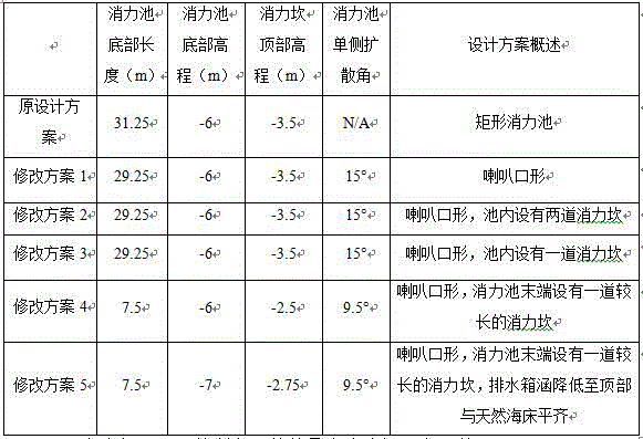
The specific parameters and points of each protocol are shown in table 1 below:
TABLE 1 stilling pool scenarios
The maximum flow rates at the control section under different scenarios and conditions are shown in table 2 below:
TABLE 2 maximum flow Rate at control section under different scenarios and conditions (prototype)

The test results are shown in FIGS. 9 to 30. From the test results of fig. 9 to 12, it can be seen that the absorption basin of the original design scheme has a large size, but the flow rate of the control section still cannot meet the specified requirements.
The modification schemes 4-5 are novel energy dissipater body types provided by the invention, the tail part of the stilling pool is changed into a novel energy dissipation flow guide ridge, the ridge is higher than the side wall of the stilling pool, the volume length of the stilling pool is only 1/3 of other schemes, the engineering quantity is saved, the requirement of flow rate control is met, and the navigation safety can be ensured.
In the modification 4-5, preferably, when the tail energy dissipation flow guide ridge is the riprap, the slope of the upstream side of the energy dissipation flow guide ridge is 1:1.5, so that the stability of the riprap is ensured and the energy dissipation effect is enhanced; when the tail energy dissipation and flow guide ridge is cast by concrete, the upstream side slope of the energy dissipation and flow guide ridge is 1:0.5, and the energy dissipation effect can be enhanced by the steep slope.
In a coastal power plant, because the drainage of the power plant also contains a large amount of plankton organic matters, suspended matters and remains of algae and plants, and carries a large amount of foam, in severe cases, the foam is gathered within a range of several kilometers of a discharge outlet, the accumulation time is long, the foam is not easy to dissipate, and the foam has adverse effects on the sea environment near the power plant. Drainage siphon wells and drainage outlet energetics aeration are the main source of foam. In order to avoid the generation of foam by an energy dissipater, the invention carries out defoaming demonstration on the design scheme, and avoids the generation of foam by water aeration in a gentle slope outflow mode. Preferably, the model test result shows that in order to avoid visual pollution caused by a large amount of foam generated by drop aeration on the side wall (such as the side wall is higher than the river bed or the seabed) of the stilling basin and the back water side of the energy dissipation flow guide ridge for drainage, the slope of the side wall (such as the side wall is higher than the river bed or the seabed) of the stilling basin and the back water side slope of the energy dissipation flow guide ridge on the back water side should be less than or equal to 1: 10.
Based on the test, the invention discloses a thermonuclear power plant water outlet energy dissipater which is suitable for open channel drainage or a lateral drainage mode of a drainage box culvert 1 as shown in figure 31; the energy dissipater comprises a stilling pool 2 and an energy dissipation flow guide ridge 4 blocked on a water outlet in the stilling pool; the energy dissipater is bilaterally symmetrical along the water flow direction, the energy dissipation flow guide ridge 4 is positioned at the outlet of the stilling pool 2 and is perpendicular to the water flow direction of the outlet of the open channel or the drainage box culvert, and the top elevation of the side wall 3 of the stilling pool is lower than that of the energy dissipation flow guide ridge 4. After the water discharged from the open channel or the drainage box culvert 1 is fully dissipated by energy dissipaters, the flow velocity at the downstream side of the energy dissipation flow guide ridge 4 is remarkably reduced under the blocking action of the energy dissipation flow guide ridge 4, the transverse flow velocity of water flow in the water area just facing the water outlet can be reduced, and the navigation safety of ships is facilitated.
Correspondingly, based on the optimization conclusion obtained from the test result, the top elevation of the energy dissipation flow guide ridge 4 is higher than the side wall of the stilling pool by more than 0.3m, and the length of the energy dissipation flow guide ridge 4 is larger than the width of the water outlet of the stilling pool by more than 2 m. Preferably, the two side walls 3 of the stilling pool are arranged in a central symmetry mode, and the single-side diffusion angle of each side wall is 8-10 degrees. Preferably, when the main body of the energy dissipation and flow guiding ridge 4 is made of concrete, the slope of the energy dissipation and flow guiding ridge 4 on the side close to the stilling pool is not less than 1: 0.5. Preferably, when the main body of the energy dissipation and flow guide ridge 4 is made of riprap materials, the slope of the energy dissipation and flow guide ridge on the side close to the stilling pool direction is not more than 1: 1.5. Preferably, the gradient of the stilling pool side wall 3 at the side far away from the pool inner direction is not more than 1: 10; the gradient of the energy dissipation flow guide ridge 4 on the side far away from the stilling pool is not more than 1: 10.
The above description is only for the purpose of illustrating the preferred embodiments of the present invention and is not to be construed as limiting the invention, and any modifications, equivalents and improvements made within the spirit and principle of the present invention are intended to be included within the scope of the present invention.
Claims (6)
Priority Applications (1)
| Application Number | Priority Date | Filing Date | Title |
|---|---|---|---|
| CN202111489515.9A CN113981916A (en) | 2021-12-08 | 2021-12-08 | Energy dissipater for water outlet of thermonuclear power plant |
Applications Claiming Priority (1)
| Application Number | Priority Date | Filing Date | Title |
|---|---|---|---|
| CN202111489515.9A CN113981916A (en) | 2021-12-08 | 2021-12-08 | Energy dissipater for water outlet of thermonuclear power plant |
Publications (1)
| Publication Number | Publication Date |
|---|---|
| CN113981916A true CN113981916A (en) | 2022-01-28 |
Family
ID=79733483
Family Applications (1)
| Application Number | Title | Priority Date | Filing Date |
|---|---|---|---|
| CN202111489515.9A Pending CN113981916A (en) | 2021-12-08 | 2021-12-08 | Energy dissipater for water outlet of thermonuclear power plant |
Country Status (1)
| Country | Link |
|---|---|
| CN (1) | CN113981916A (en) |
Citations (5)
| Publication number | Priority date | Publication date | Assignee | Title |
|---|---|---|---|---|
| US6059490A (en) * | 1998-05-05 | 2000-05-09 | Kauppi; Frederick J. | Hydraulic energy dissipating offset stepped spillway and methods of constructing and using the same |
| US20050111916A1 (en) * | 2001-11-27 | 2005-05-26 | Dusan Ciuha | Spilway with improved dissipation efficiency |
| CN204475477U (en) * | 2015-01-23 | 2015-07-15 | 中水北方勘测设计研究有限责任公司 | A kind of circulating-water in thermal power plant drain structure for water |
| CN207003391U (en) * | 2017-07-17 | 2018-02-13 | 浙江省水利河口研究院 | A kind of water gate energy-dissipating installation |
| CN214738637U (en) * | 2021-02-19 | 2021-11-16 | 山东电力工程咨询院有限公司 | Water outlet structure of power plant |
-
2021
- 2021-12-08 CN CN202111489515.9A patent/CN113981916A/en active Pending
Patent Citations (5)
| Publication number | Priority date | Publication date | Assignee | Title |
|---|---|---|---|---|
| US6059490A (en) * | 1998-05-05 | 2000-05-09 | Kauppi; Frederick J. | Hydraulic energy dissipating offset stepped spillway and methods of constructing and using the same |
| US20050111916A1 (en) * | 2001-11-27 | 2005-05-26 | Dusan Ciuha | Spilway with improved dissipation efficiency |
| CN204475477U (en) * | 2015-01-23 | 2015-07-15 | 中水北方勘测设计研究有限责任公司 | A kind of circulating-water in thermal power plant drain structure for water |
| CN207003391U (en) * | 2017-07-17 | 2018-02-13 | 浙江省水利河口研究院 | A kind of water gate energy-dissipating installation |
| CN214738637U (en) * | 2021-02-19 | 2021-11-16 | 山东电力工程咨询院有限公司 | Water outlet structure of power plant |
Similar Documents
| Publication | Publication Date | Title |
|---|---|---|
| CN104234174B (en) | A kind of combined type froth breaking siphonic water-collecting well and method | |
| CN107190712B (en) | A kind of toe bank falls bank stiling basin formula underflow energy dissipator and design method | |
| CN114319261B (en) | Vertical seam type fishway with H-shaped piers and short baffle plates | |
| CN203188185U (en) | United energy dissipation structure under ultralow Froude number | |
| CN106836117A (en) | A kind of porous floating breakwater | |
| CN103174109B (en) | Rapid-slow flow smooth transition flow diversion system for riverway intersection area | |
| CN106337401B (en) | Flow-guiding type classified energy-dissipation defoaming siphonic water-collecting well and method before a kind of weir flow | |
| CN104563267A (en) | Compound key overflow weir type siphon well and method implemented by same | |
| CN106400753A (en) | Key weir flow-type classified energy dissipation defoaming siphon well and method | |
| CN106013009B (en) | A kind of more counter-slope formula stiling basins | |
| Liu et al. | Optimization schemes to significantly improve the upstream migration of fish: A case study in the lower Yangtze River basin | |
| CN203247560U (en) | Solid float type rubber floating debris obstructing row | |
| CN113981916A (en) | Energy dissipater for water outlet of thermonuclear power plant | |
| CN113109528B (en) | An engineering measure to reduce the supersaturation of dissolved gas in the water body under the dam | |
| CN215562317U (en) | Flow guiding and energy dissipating facility with flow dividing port | |
| CN212294570U (en) | An energy dissipation pool with an inverted triangular wedge tail pier | |
| CN206220066U (en) | Passed the flood period the choosing of the breach flow, down stream energy-dissipating structure for gravity dam bank | |
| Mao et al. | Research on the Protective Effect of Twin-groyne Arrangement on Riverbank | |
| CN204370385U (en) | A kind of shallow top layer submersible submerged jets energy-dissipating structure | |
| Kiraga et al. | Conventional pool fish pass project for small threshold | |
| Feng et al. | Eco-environmentally friendly operational regulation: an effective strategy to diminish the TDG supersaturation of reservoirs. | |
| CN119578119B (en) | A numerical simulation method of wave hydrodynamics in sea areas with bamboo fences and shrub dams | |
| CN103276690A (en) | Method for governing pebble sand wave beaches on upper reaches of Yangtze River | |
| CN117127547A (en) | Fish collecting system based on fish blocking weir | |
| Liu et al. | Study on the influence of different river widening schemes on river |
Legal Events
| Date | Code | Title | Description |
|---|---|---|---|
| PB01 | Publication | ||
| PB01 | Publication | ||
| SE01 | Entry into force of request for substantive examination | ||
| SE01 | Entry into force of request for substantive examination |