CN113950552B - Load handling machine and method for controlling a load handling machine - Google Patents
Load handling machine and method for controlling a load handling machine Download PDFInfo
- Publication number
- CN113950552B CN113950552B CN202080042100.4A CN202080042100A CN113950552B CN 113950552 B CN113950552 B CN 113950552B CN 202080042100 A CN202080042100 A CN 202080042100A CN 113950552 B CN113950552 B CN 113950552B
- Authority
- CN
- China
- Prior art keywords
- machine
- control device
- control
- operator
- operating unit
- Prior art date
- Legal status (The legal status is an assumption and is not a legal conclusion. Google has not performed a legal analysis and makes no representation as to the accuracy of the status listed.)
- Active
Links
Images


Classifications
-
- B—PERFORMING OPERATIONS; TRANSPORTING
- B66—HOISTING; LIFTING; HAULING
- B66F—HOISTING, LIFTING, HAULING OR PUSHING, NOT OTHERWISE PROVIDED FOR, e.g. DEVICES WHICH APPLY A LIFTING OR PUSHING FORCE DIRECTLY TO THE SURFACE OF A LOAD
- B66F9/00—Devices for lifting or lowering bulky or heavy goods for loading or unloading purposes
- B66F9/06—Devices for lifting or lowering bulky or heavy goods for loading or unloading purposes movable, with their loads, on wheels or the like, e.g. fork-lift trucks
- B66F9/065—Devices for lifting or lowering bulky or heavy goods for loading or unloading purposes movable, with their loads, on wheels or the like, e.g. fork-lift trucks non-masted
-
- E—FIXED CONSTRUCTIONS
- E02—HYDRAULIC ENGINEERING; FOUNDATIONS; SOIL SHIFTING
- E02F—DREDGING; SOIL-SHIFTING
- E02F3/00—Dredgers; Soil-shifting machines
- E02F3/04—Dredgers; Soil-shifting machines mechanically-driven
- E02F3/28—Dredgers; Soil-shifting machines mechanically-driven with digging tools mounted on a dipper- or bucket-arm, i.e. there is either one arm or a pair of arms, e.g. dippers, buckets
-
- B—PERFORMING OPERATIONS; TRANSPORTING
- B60—VEHICLES IN GENERAL
- B60K—ARRANGEMENT OR MOUNTING OF PROPULSION UNITS OR OF TRANSMISSIONS IN VEHICLES; ARRANGEMENT OR MOUNTING OF PLURAL DIVERSE PRIME-MOVERS IN VEHICLES; AUXILIARY DRIVES FOR VEHICLES; INSTRUMENTATION OR DASHBOARDS FOR VEHICLES; ARRANGEMENTS IN CONNECTION WITH COOLING, AIR INTAKE, GAS EXHAUST OR FUEL SUPPLY OF PROPULSION UNITS IN VEHICLES
- B60K28/00—Safety devices for propulsion-unit control, specially adapted for, or arranged in, vehicles, e.g. preventing fuel supply or ignition in the event of potentially dangerous conditions
- B60K28/02—Safety devices for propulsion-unit control, specially adapted for, or arranged in, vehicles, e.g. preventing fuel supply or ignition in the event of potentially dangerous conditions responsive to conditions relating to the driver
- B60K28/04—Safety devices for propulsion-unit control, specially adapted for, or arranged in, vehicles, e.g. preventing fuel supply or ignition in the event of potentially dangerous conditions responsive to conditions relating to the driver responsive to presence or absence of the driver, e.g. to weight or lack thereof
-
- B—PERFORMING OPERATIONS; TRANSPORTING
- B66—HOISTING; LIFTING; HAULING
- B66F—HOISTING, LIFTING, HAULING OR PUSHING, NOT OTHERWISE PROVIDED FOR, e.g. DEVICES WHICH APPLY A LIFTING OR PUSHING FORCE DIRECTLY TO THE SURFACE OF A LOAD
- B66F17/00—Safety devices, e.g. for limiting or indicating lifting force
- B66F17/003—Safety devices, e.g. for limiting or indicating lifting force for fork-lift trucks
-
- B—PERFORMING OPERATIONS; TRANSPORTING
- B66—HOISTING; LIFTING; HAULING
- B66F—HOISTING, LIFTING, HAULING OR PUSHING, NOT OTHERWISE PROVIDED FOR, e.g. DEVICES WHICH APPLY A LIFTING OR PUSHING FORCE DIRECTLY TO THE SURFACE OF A LOAD
- B66F9/00—Devices for lifting or lowering bulky or heavy goods for loading or unloading purposes
- B66F9/06—Devices for lifting or lowering bulky or heavy goods for loading or unloading purposes movable, with their loads, on wheels or the like, e.g. fork-lift trucks
- B66F9/065—Devices for lifting or lowering bulky or heavy goods for loading or unloading purposes movable, with their loads, on wheels or the like, e.g. fork-lift trucks non-masted
- B66F9/0655—Devices for lifting or lowering bulky or heavy goods for loading or unloading purposes movable, with their loads, on wheels or the like, e.g. fork-lift trucks non-masted with a telescopic boom
-
- B—PERFORMING OPERATIONS; TRANSPORTING
- B66—HOISTING; LIFTING; HAULING
- B66F—HOISTING, LIFTING, HAULING OR PUSHING, NOT OTHERWISE PROVIDED FOR, e.g. DEVICES WHICH APPLY A LIFTING OR PUSHING FORCE DIRECTLY TO THE SURFACE OF A LOAD
- B66F9/00—Devices for lifting or lowering bulky or heavy goods for loading or unloading purposes
- B66F9/06—Devices for lifting or lowering bulky or heavy goods for loading or unloading purposes movable, with their loads, on wheels or the like, e.g. fork-lift trucks
- B66F9/075—Constructional features or details
- B66F9/0759—Details of operating station, e.g. seats, levers, operator platforms, cabin suspension
-
- E—FIXED CONSTRUCTIONS
- E02—HYDRAULIC ENGINEERING; FOUNDATIONS; SOIL SHIFTING
- E02F—DREDGING; SOIL-SHIFTING
- E02F3/00—Dredgers; Soil-shifting machines
- E02F3/04—Dredgers; Soil-shifting machines mechanically-driven
- E02F3/28—Dredgers; Soil-shifting machines mechanically-driven with digging tools mounted on a dipper- or bucket-arm, i.e. there is either one arm or a pair of arms, e.g. dippers, buckets
- E02F3/36—Component parts
- E02F3/42—Drives for dippers, buckets, dipper-arms or bucket-arms
- E02F3/43—Control of dipper or bucket position; Control of sequence of drive operations
- E02F3/435—Control of dipper or bucket position; Control of sequence of drive operations for dipper-arms, backhoes or the like
-
- B—PERFORMING OPERATIONS; TRANSPORTING
- B66—HOISTING; LIFTING; HAULING
- B66F—HOISTING, LIFTING, HAULING OR PUSHING, NOT OTHERWISE PROVIDED FOR, e.g. DEVICES WHICH APPLY A LIFTING OR PUSHING FORCE DIRECTLY TO THE SURFACE OF A LOAD
- B66F9/00—Devices for lifting or lowering bulky or heavy goods for loading or unloading purposes
- B66F9/06—Devices for lifting or lowering bulky or heavy goods for loading or unloading purposes movable, with their loads, on wheels or the like, e.g. fork-lift trucks
- B66F9/075—Constructional features or details
- B66F9/0755—Position control; Position detectors
-
- B—PERFORMING OPERATIONS; TRANSPORTING
- B66—HOISTING; LIFTING; HAULING
- B66F—HOISTING, LIFTING, HAULING OR PUSHING, NOT OTHERWISE PROVIDED FOR, e.g. DEVICES WHICH APPLY A LIFTING OR PUSHING FORCE DIRECTLY TO THE SURFACE OF A LOAD
- B66F9/00—Devices for lifting or lowering bulky or heavy goods for loading or unloading purposes
- B66F9/06—Devices for lifting or lowering bulky or heavy goods for loading or unloading purposes movable, with their loads, on wheels or the like, e.g. fork-lift trucks
- B66F9/075—Constructional features or details
- B66F9/20—Means for actuating or controlling masts, platforms, or forks
Landscapes
- Engineering & Computer Science (AREA)
- Structural Engineering (AREA)
- Mechanical Engineering (AREA)
- Transportation (AREA)
- Civil Engineering (AREA)
- Life Sciences & Earth Sciences (AREA)
- Geology (AREA)
- Mining & Mineral Resources (AREA)
- General Engineering & Computer Science (AREA)
- Combustion & Propulsion (AREA)
- Chemical & Material Sciences (AREA)
- Forklifts And Lifting Vehicles (AREA)
- Operation Control Of Excavators (AREA)
- Motorcycle And Bicycle Frame (AREA)
- Vehicle Body Suspensions (AREA)
- Component Parts Of Construction Machinery (AREA)
- Control Of Position, Course, Altitude, Or Attitude Of Moving Bodies (AREA)
- Harvester Elements (AREA)
Abstract
Description
技术领域technical field
本发明涉及一种负载操纵机器,诸如具有伸缩或非伸缩提升臂的机器、动力铲、斗式装载机等,并且涉及一种用于控制负载操纵机器的方法。The present invention relates to a load handling machine, such as a machine with a telescoping or non-telescoping lift arm, a power shovel, a bucket loader, etc., and to a method for controlling a load handling machine.
背景技术Background technique
更具体地说,本发明涉及一种负载操纵机器,包括:More specifically, the present invention relates to a load handling machine comprising:
-带有轮的底盘,其装备有驾驶员站,- a chassis with wheels, which is equipped with a driver's station,
-驱动系统,其驱动带有轮的底盘的运动,- drive system, which drives the movement of the chassis with wheels,
-系统,其用于操纵负载并且由底盘承载,- system for handling loads and carried by the chassis,
-控制装置,其用于控制负载操纵系统,该控制装置能够被操作者手动致动,该控制装置包括配置成被手动抓握的手动部分,- a control device for controlling the load handling system, the control device being manually actuatable by an operator, the control device comprising a manual part configured to be manually grasped,
-操作单元,其配置成从所述控制装置接收控制信号,- an operating unit configured to receive control signals from said control device,
-致动构件,其用于能够被手动致动的控制装置,- an actuating member for a control device capable of being manually actuated,
操作单元,其配置成使得当致动构件处于致动状态时,所述操作单元至少根据从控制装置接收的控制信号而允许操作操纵系统。An operating unit configured such that when the actuating member is in an actuated state, the operating unit allows operating the steering system at least in dependence on a control signal received from the control device.
出于安全原因,法规要求采取措施来防止控制装置在负载操纵机器上意外操作。例如,由于操作者的衣服挂在控制装置上,使得操作者无意地或没有意识到地操作控制装置,可能导致意外操作。如专利EP-0.981.078和EP-1.523.704中所示,为了解决这个问题,已经开发了包括致动构件的负载操纵机器,该致动构件致动控制装置以避免使用控制装置的意外操作。文献EP-1.953.027也是这种情况。然而,这种致动构件的存在对操作者施加了限制。因此,寻求允许在不损害操作者的安全的情况下减少对操作者施加的限制的解决方案。For safety reasons, regulations require measures to prevent accidental operation of controls on load handling machines. For example, unintentional or unaware operation of the control by the operator due to the operator's clothing hanging on the control may result in unintentional operation. To solve this problem, as shown in patents EP-0.981.078 and EP-1.523.704, load-handling machines have been developed that include actuating members that actuate the controls to avoid unintentional operation using the controls . This is also the case with document EP-1.953.027. However, the presence of such an actuation member imposes constraints on the operator. Therefore, a solution is sought that allows reducing the constraints imposed on the operator without compromising the safety of the operator.
发明内容Contents of the invention
本发明的目的是提出一种上述类型的负载操纵机器,其设计使得可以在不损害操作者的安全的情况下减少对操作者施加的限制。The object of the present invention is to propose a load-handling machine of the above-mentioned type, designed in such a way that the constraints imposed on the operator can be reduced without compromising the safety of the operator.
为此,本发明的一个主题是一种负载操纵机器,包括:To this end, a subject of the invention is a load handling machine comprising:
-底盘,其装备有驾驶员站,- chassis, which is equipped with a driver's station,
-系统,其用于操纵负载并且由底盘承载,- system for handling loads and carried by the chassis,
控制装置,其用于控制负载操纵系统,该控制装置能够被操作者手动致动,该控制装置包括配置成被手动抓握的手动部分,a control device for controlling the load handling system, the control device being manually actuatable by an operator, the control device comprising a manual portion configured to be manually grasped,
-操作单元,其配置成从所述控制装置接收控制信号,- an operating unit configured to receive control signals from said control device,
-致动构件,其用于致动能够被手动致动的控制装置,操作单元配置成使得在致动构件的致动状态下至少根据从控制装置接收的控制信号而允许操作操纵系统,- an actuating member for actuating a control device that can be manually actuated, the operating unit being configured such that in an actuated state of the actuating member at least in accordance with a control signal received from the control device, the operating system is allowed to be operated,
其中,驾驶员站装备有检测系统,该检测系统能够检测在所述站处操作者的存在或不存在(即是否存在操作者),该检测系统至少包括与控制装置不同的存在传感器,并且操作单元配置成使得,当致动构件处于致动构件已经从致动状态转换到非致动状态之后的所述非致动状态时,所述操作单元至少根据由用于检测在所述站处操作者的存在的检测系统检测到的操作者不存在或操作者存在的状态来阻止或允许使用控制装置操作操纵系统。这种用于检测操作者的存在或不存在的系统的存在使得例如使致动构件能够保持在非致动状态的时间段延长而不损害操作者的安全成为可能。Wherein, the driver's station is equipped with a detection system capable of detecting the presence or absence of an operator at said station (ie whether there is an operator), the detection system comprising at least a presence sensor different from the control device, and operating The unit is configured such that, when the actuation member is in said non-actuated state after the actuation member has transitioned from the actuated state to the non-actuated state, said operating unit operates at said station at least according to detection by a The absence or presence of an operator detected by the operator presence detection system prevents or permits operation of the steering system using the control means. The presence of such a system for detecting the presence or absence of an operator makes it possible, for example, to prolong the period of time for which the actuating member can remain in the non-actuated state without compromising the safety of the operator.
根据本发明的一个实施例,操纵机器包括感测指示机器的运动的参数的传感器(参数传感器),并且操作单元配置成至少根据指示机器的运动的参数而允许使用控制装置操作操纵系统。此外,这种布置使得可以限制对操作者施加的关于致动构件的限制,并且在机器的行驶阶段期间提高驾驶舒适性,而不会损害操作者的安全。According to one embodiment of the invention, the steering machine comprises a sensor (parameter sensor) sensing a parameter indicative of the motion of the machine, and the operating unit is configured to allow the steering system to be operated using the control means at least according to the parameter indicative of the motion of the machine. Furthermore, this arrangement makes it possible to limit the constraints imposed on the operator with respect to the actuation members and to increase the driving comfort during the running phase of the machine without compromising the safety of the operator.
根据本发明的一个实施例,指示机器的运动的参数的传感器是指示机器的行进速度的参数的传感器,机器包括用于存储机器的预定行进速度的存储器,并且操作单元配置成使得,当用于致动控制装置的致动构件处于非致动状态时,所述操作单元在由指示机器的行进速度的参数的传感器提供的机器的行进速度大于存储在存储器中的预定值的情况下允许使用控制装置操作操纵系统。According to one embodiment of the invention, the sensor of the parameter indicative of the movement of the machine is a sensor of the parameter indicative of the travel speed of the machine, the machine comprises a memory for storing a predetermined travel speed of the machine, and the operating unit is configured such that, when used When the actuation member of the actuation control device is in a non-actuated state, said operating unit allows the use of the control in the event that the speed of travel of the machine, provided by a sensor of a parameter indicative of the speed of travel of the machine, is greater than a predetermined value stored in a memory Device operation manipulation system.
根据本发明的一个实施例,操作单元配置成启动至少一个被称为存在计时器的计时器,该存在计时器限定当致动构件从致动状态转换到非致动状态的时间间隔,并且操作单元配置成在由存在计时器限定的时间间隔已经过去时,阻止使用由控制装置提供到操作单元的控制信号操作操纵系统,并且操作单元配置成至少根据由用于检测操作者在所述站处的存在的检测系统检测到的操作者不存在或操作者存在的状态来重置存在计时器。According to one embodiment of the invention, the operating unit is configured to start at least one timer, called a presence timer, which defines a time interval when the actuating member transitions from an actuated state to a non-actuated state, and operates The unit is configured to prevent the manipulation system from being operated using a control signal provided by the control means to the operating unit when a time interval defined by the presence timer has elapsed, and the operating unit is configured to at least depend on the The presence detection system detects the absence of the operator or the presence of the operator to reset the presence timer.
根据本发明的一个实施例,操作单元配置成当用于检测操作者在所述站处的存在的检测系统检测到操作者的不存在时阻止存在计时器的重置。According to one embodiment of the invention, the operating unit is configured to prevent resetting of the presence timer when the detection system for detecting the presence of the operator at said station detects the absence of the operator.
根据本发明的一个实施例,操作单元配置成至少根据从控制装置接收的控制信号来重置存在计时器。According to an embodiment of the invention, the operating unit is configured to reset the presence timer in dependence on at least a control signal received from the control device.
根据本发明的一个实施例,操作单元配置成根据由指示机器的运动的参数的传感器提供的数据来重置存在计时器。According to one embodiment of the invention, the operating unit is configured to reset the presence timer according to the data provided by the sensor indicative of a parameter of the movement of the machine.
根据本发明的一个实施例,操作单元配置成启动至少一个被称为控制计时器的计时器,该控制计时器限定致动构件从致动状态转换到非致动状态的时间间隔,并且操作单元配置成在由控制计时器限定的时间间隔已经过去时阻止使用控制装置操作操纵系统,并且操作单元配置成至少根据由指示机器的运动的参数的传感器提供的数据并且在适当的情况下至少根据从控制装置接收的控制信号来重置控制计时器。According to one embodiment of the invention, the operating unit is configured to start at least one timer, referred to as a control timer, which defines a time interval for the transition of the actuating member from the actuated state to the inactive state, and the operating unit configured to prevent the use of the control device from operating the steering system when a time interval defined by the control timer has elapsed, and the operating unit is configured to rely at least on data provided by a sensor indicative of a parameter of motion of the machine and, where appropriate, at least from The control signal received by the control device resets the control timer.
根据本发明的一个实施例,由控制计时器限定的时间间隔的持续时间大于由存在计时器限定的时间间隔的持续时间。因此,在存在操作者的情况下,可以提供改进的驾驶舒适性而不损害操作者的安全。According to one embodiment of the invention, the duration of the time interval defined by the control timer is greater than the duration of the time interval defined by the presence timer. Thus, in the presence of an operator, improved driving comfort can be provided without compromising the safety of the operator.
根据本发明的一个实施例,控制操纵系统的控制装置是包括至少两个控制元件的控制装置。According to one embodiment of the invention, the control device controlling the maneuvering system is a control device comprising at least two control elements.
根据本发明的一个实施例,机器包括驱动带有轮的底盘的运动的驱动系统,用于控制操纵系统的控制装置是多功能控制装置,并且控制元件中的至少一个配置成控制操纵系统的至少一部分,并且控制元件中的其它控制元件或另一控制元件配置成控制驱动机器的运动的驱动系统的至少一部分。According to one embodiment of the invention, the machine comprises a drive system for driving the movement of the wheeled chassis, the control device for controlling the steering system is a multifunctional control device, and at least one of the control elements is configured to control at least one of the steering system A portion of the control element, and the other of the control elements or another control element is configured to control at least a portion of a drive system that drives the motion of the machine.
根据本发明的一个实施例,致动构件由用于控制操纵系统的控制装置承载。According to one embodiment of the invention, the actuating member is carried by a control device for controlling the steering system.
根据本发明的一个实施例,致动构件是用于检测操作者的手在控制装置的手动部分上的存在的传感器。According to one embodiment of the invention, the actuating member is a sensor for detecting the presence of the operator's hand on the manual part of the control device.
根据本发明的一个实施例,操纵系统包括安装在所述底盘上能围绕水平旋转轴线旋转的至少一个操纵臂和驱动所述操纵臂围绕所述水平旋转轴线运动的至少一个致动器。According to an embodiment of the present invention, the steering system includes at least one steering arm mounted on the chassis and capable of rotating around a horizontal rotation axis, and at least one actuator driving the steering arm to move around the horizontal rotation axis.
根据本发明的一个实施例,驾驶员站采用操作室的形式,在操作室内有至少一个操作者可坐在其上的座椅,所述操作室通过门关闭,并且用于检测在所述站处操作者的存在的检测系统的存在传感器或存在传感器中的至少一个装备于所述座椅。According to one embodiment of the invention, the driver's station takes the form of an operator's compartment in which there is at least one seat on which the operator can sit, said operator's compartment being closed by a door and used for detecting The seat is equipped with a presence sensor or at least one of a presence sensor of the operator's presence detection system.
根据本发明的一个实施例,用于检测在所述站处操作者的存在的系统包括用于检测门的打开和/或关闭的至少一个传感器。According to one embodiment of the invention, the system for detecting the presence of an operator at said station comprises at least one sensor for detecting opening and/or closing of a door.
本发明的另一个主题是一种用于控制负载操纵机器的方法,所述负载操纵机器包括:Another subject of the invention is a method for controlling a load handling machine comprising:
-底盘,其装备有驾驶员站,- chassis, which is equipped with a driver's station,
-系统,其用于操纵负载并且由底盘承载,- system for handling loads and carried by the chassis,
控制装置,其用于控制负载操纵系统,该控制装置能够被操作者手动致动,该控制装置包括配置成被手动抓握的手动部分,a control device for controlling the load handling system, the control device being manually actuatable by an operator, the control device comprising a manual portion configured to be manually grasped,
-操作单元,其配置成从所述控制设备接收控制信号,- an operating unit configured to receive control signals from said control device,
-致动构件,其用于致动能够被手动致动的控制装置,所述方法包括手动致动致动构件以致动控制装置的步骤,从而在致动构件的致动状态下至少根据从控制装置接收的控制信号而允许操作操纵系统,- an actuating member for actuating a control device capable of being manually actuated, the method comprising the step of manually actuating the actuating member to actuate the control device so that in the actuated state of the actuating member at least according to the slave control The control signal received by the device allows the operation of the steering system,
其中,驾驶员站装备有检测系统,检测系统能够检测所述站处操作者的存在或不存在,该检测系统至少包括与控制装置不同的存在传感器,该方法包括当致动构件处于致动构件已经从致动状态转换到非致动状态之后的非致动状态时,至少根据由用于检测所述站处操作者的存在的检测系统检测到的操作者不存在或操作者存在的状态来允许或阻止使用控制装置操作操纵系统的步骤。wherein the driver's station is equipped with a detection system capable of detecting the presence or absence of an operator at said station, the detection system comprising at least a presence sensor distinct from the control device, the method comprising when the actuating member is in the actuating member When a non-actuated state after having transitioned from an actuated state to a non-actuated state, at least based on the absence or presence of an operator detected by the detection system for detecting the presence of an operator at said station The step of allowing or preventing the use of controls to operate a steering system.
附图说明Description of drawings
在参考附图阅读以下示例性实施例的描述时,将清楚地理解本发明,在附图中:The present invention will be clearly understood when reading the following description of exemplary embodiments with reference to the accompanying drawings, in which:
图1描绘了根据本发明的负载操纵机器的示意图,其中提升臂处于升高位置;Figure 1 depicts a schematic view of a load handling machine according to the invention with the lift arm in a raised position;
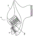
图2描绘了根据本发明的负载操纵机器的透视图,其中提升臂处于降低位置;Figure 2 depicts a perspective view of a load handling machine according to the invention with the lift arm in a lowered position;
图3描绘了从致动构件侧观察的控制装置的局部视图;Figure 3 depicts a partial view of the control device viewed from the side of the actuating member;
图4描绘了从与致动构件侧相反的一侧观察的控制装置的局部视图;Figure 4 depicts a partial view of the control device from the side opposite the actuating member side;
图5是机器的部件的示意图;Figure 5 is a schematic diagram of the components of the machine;
图6是可由图1的操纵机器实施的控制方法的示意图;FIG. 6 is a schematic diagram of a control method that may be implemented by the manipulating machine of FIG. 1;
图7是可由图1的操纵装置实施的控制方法的示意图。FIG. 7 is a schematic diagram of a control method that can be implemented by the manipulator of FIG. 1 .
具体实施方式Detailed ways
下面将参照附图更详细地描述本发明的构思,附图示出了本发明的构思的各实施例。在整个说明书中对“一个实施例”的引用意味着结合一个实施例描述的特定功能、结构或特征被包括在本发明的至少一个实施例中。因此,在整个说明书的各个地方出现的表述“在一个实施例中”不一定是指同一个实施例。此外,特定功能、结构或特征可以以任何合适的方式组合在一个或多个实施例中。The inventive concept will be described in more detail hereinafter with reference to the accompanying drawings, which show various embodiments of the inventive concept. Reference to "one embodiment" throughout the specification means that a specific function, structure, or characteristic described in connection with one embodiment is included in at least one embodiment of the present invention. Thus, appearances of the expression "in one embodiment" in various places throughout the specification are not necessarily referring to the same embodiment. Furthermore, particular functions, structures or characteristics may be combined in any suitable manner in one or more embodiments.
如上所述,本发明涉及一种根据图1所示的负载操纵机器1。该机器1包括底盘2。在所描绘的示例中,该底盘2装备有用于支承在地面上的轮子20,从而形成带有轮的底盘2。该底盘2上安装有驾驶员站15。该驾驶员站15采用操作室151的形式,在该操作室内有操作者可以坐的至少一个座位18。操作室151通过门19关闭。如在描绘的示例中,机器1还可以包括通过驱动机器1的轮子20的旋转运动来驱动带有轮的底盘2的运动的驱动系统3。驱动底盘2的该驱动系统3以本身已知的方式包括通过传动装置连接到轮子20的内燃机。驱动底盘2运动的该驱动系统3尤其使用位于操作室151中的未示出的油门踏板来控制。As already mentioned above, the invention relates to a
操纵机器1还包括用于操纵负载并由底盘2承载的系统4。该操纵系统4包括安装在所述底盘2上可绕水平旋转轴线21旋转的至少一个操纵臂13和驱动所述操纵臂13绕水平旋转轴线21运动的至少一个致动器14。因此,操纵臂13是枢转臂,其被安装成能够绕垂直于臂的纵轴线的水平轴线21枢转,使得臂13可以使用致动器14从降低位置移动到升高位置,反之亦然,所述致动器诸如为通过液压回路连接到液压泵的液压油缸,泵和回路未被示出。臂可以是伸缩臂,其长度可以在臂的缩回位置和伸展位置之间调节。为此,臂13可以由两个臂部分形成,其中一个臂部分被称为第一部分,第一部分能够枢转地联接到底盘10,并且其中另一个臂部分被称为第二部分,第二部分嵌套在第一臂部分中,能够在第一臂部分中滑动。作为替代,臂可以不是可伸缩的。The handling
两个臂部分的嵌套滑动相对运动可以使用机器的第二致动器获得,该第二致动器诸如为双动式油缸,其容纳在第一臂部分中并且通过油缸杆固定到第二臂部分,以允许臂部分在油缸杆缩回或伸展的作用下被驱动相对运动。Nested sliding relative motion of the two arm sections can be obtained using a second actuator of the machine, such as a double acting cylinder housed in the first arm section and secured to the second arm section by a cylinder rod. The arm part is used to allow the arm part to be driven to move relatively under the action of the retraction or extension of the cylinder rod.
负载操纵臂13可在其自由端处装备有通过枢转连接而连接到臂的附件23。该附件23可以通过致动器25而围绕枢转连接的枢轴被驱动,该致动器也可以由双动式液压油缸形成或由平行且依次操作的两个单动式油缸形成。The
在所描绘的示例中,该附件23包括叉配件,并且致动器25通过该附件绕垂直于臂13的纵轴线的被称为水平轴线的轴线枢转而允许叉配件在拾取位置和卸载位置之间移动。该枢转轴线平行于臂13连接到底盘10所绕的枢转轴线21。卸载位置对应于叉配件的朝向地面枢转的极限位置。叉配件的拾取位置对应于叉配件和相关负载24(当存在这种负载时)的向上枢转位置。In the example depicted, the
操纵机器1还包括操作单元5,操作单元5配置成控制致动器14和致动器25的操作,并且在适当的情况下,当存在伸缩装置时,控制伸缩装置的伸展,使得可以引起臂13和附件23的运动。The handling
操作单元5是电子和/或计算机化单元,其例如包括与存储器相关联的微控制器或微处理器。因此,当陈述单元或属于所述单元的装置配置成执行给定操作时,这意味着该单元包括使得可以执行所述操作的计算机指令和相应的执行装置和/或相应的电子部件。The
换言之,所描述的功能和步骤可以以计算机程序的形式或经由硬件组件(例如可编程门阵列)来实现。特别地,由操作单元5执行的功能和步骤可以由在处理器或控制器中实现的指令集或计算机模块来执行,或者由专用电子部件或FPGA或ASIC部件来执行。也可以将计算机部件和电子部件结合。In other words, the described functions and steps can be implemented in the form of computer programs or via hardware components such as programmable gate arrays. In particular, the functions and steps performed by the
因此,操作单元5通过经由液压回路控制相应的致动器14和致动器25来控制操纵系统4,尤其是控制臂13和附件23的运动。Thus, the
由操作单元5提供的控制信号通常作用于设置在泵和致动器14、25之间的连接部中的构件(诸如分配器或阀等),以便允许以本身已知的方式将流体适当地提供给致动器14、25。The control signals provided by the
操纵机器1还包括用于控制负载操纵系统4的控制装置6。该控制装置6是手动致动的并且能够向操作单元5提供控制信号。这些控制信号由操作单元5处理。操作单元5根据这些控制信号产生用于控制至少如上所述的负载操纵系统4的控制信号。The handling
在所描绘的示例中,用于控制负载操纵系统4的控制装置6是多功能控制装置6。具体地说,控制装置6一方面可以用于控制操纵系统4,并且另一方面可以用于控制驱动机器1的运动的系统3。在变型中,控制装置6可以是仅允许控制操纵系统4的控制装置。在下文中,将总是考虑控制装置6是多功能控制装置。因此,用于控制操纵系统4的该控制装置6包括至少两个控制元件。在所描绘的示例中,图中示为10的一个控制元件配置成控制操纵系统4的至少一部分,而图中示为11的另一控制元件配置成控制驱动机器1的运动的系统3的至少一部分。还存在图中示为12a和12b的其它控制元件。该控制装置6可以采用各种形式。In the depicted example, the
在图1、图3和图4所描绘的示例中,用于控制操纵系统4的控制装置6的控制元件10是机器的操作者可以用手操纵的杆或操纵杆,并且其它控制元件11、12a、12b由所述杆承载。这些其它控制元件位于杆的圆头部(pommel)上。该杆的圆头部对应于控制装置6的手动部分61,并且构造成当控制装置根据其目的被抓握在手中时被抓握。In the example depicted in FIGS. 1 , 3 and 4 , the
这种控制装置是本领域技术人员公知的,并且这种控制装置的示例例如在专利FR-2.858.861中描述。Such control means are well known to those skilled in the art and examples of such control means are described, for example, in patent FR-2.858.861.
控制杆或操纵杆以本身已知的方式将位置信号从所述杆传送到操作单元5。这些位置信号可以被操作单元5解释为用于指示臂13和/或附件23的移动的信号。The control lever or joystick transmits position signals from said lever to the
根据一个实施例,控制杆可以因此朝向机器的前部向前移动、朝向机器的后部向后移动、或朝向机器的左部或左部向左或向右移动。在所描绘的示例中,该控制杆至少能够在向前/向后方向上朝向机器的前部/后部移动,以安装成能够向前移动而控制臂13的下降,以及向后移动而控制臂13的上升。控制杆的向前/向后移动因此可以控制第一致动器14在臂13和底盘2之间的操作。该控制杆10还可以安装成能够在横向于向前/向后方向的左/右方向上移动,以便向左移动以控制附件23的拾取位置,并且向右移动以控制附件23的卸载位置。控制杆的左/右移动因此控制在附件23和臂13之间的致动器25的操作。这些向前/向后和左/右方向对应于主方向,并且控制杆可以沿无限多个方向被驱动,控制杆在给定方向上的移动对应于控制杆相对于主方向的位置的成比例的组合动作。如图4所示,控制杆可以装备有控制元件12a(诸如旋钮等),用于控制伸缩致动器,以便在伸缩臂13的情况下向外伸出。因此,由控制杆承载的旋钮沿一个方向的旋转允许臂13通过臂13的第二臂部分在臂13的延伸方向上的滑动运动而伸展,并且由控制杆承载的旋钮沿相反方向的旋转允许臂缩回。According to one embodiment, the control lever may thus be moved forward towards the front of the machine, backward towards the rear of the machine, or left or right towards the left or left of the machine. In the example depicted, the control lever is movable at least in a forward/rearward direction towards the front/rear of the machine, so as to be mounted to be able to move forward to control the lowering of the
可以设置其它按钮、旋钮等(诸如图3中以12b所示的按钮、旋钮等),用于控制附件的某些功能。控制元件中的一个(在图中以11示出)配置成控制驱动机器的运动的系统3的至少一部分。该控制元件11可以由具有三个稳定位置的换向按钮形成,以便使机器以向前行进操作、在空档位置停止、或以反向行进操作。驱动底盘2的运动的系统3的传动装置可以包括变速箱,并且变速箱升档和降档控制可以使用按钮或由杆承载的一些其它控制构件来执行。因此,应当理解,这些控制元件可以非限制性地以旋钮、开关、按钮、转换开关、传感器(特别是霍尔效应传感器)、电位计等形式实现。Other buttons, knobs, etc., such as those shown at 12b in FIG. 3, may be provided for controlling certain functions of the accessory. One of the control elements, shown at 11 in the figure, is configured to control at least a part of the
当操作者的手定位在控制装置6的手动部分61上时,该控制杆和由该控制杆承载的控制元件可以由操作者仅用一只手致动,这里该手动部分由控制杆的圆头部的至少一部分形成。The control lever and the control elements carried by the control lever can be actuated by the operator with only one hand when the operator's hand is positioned on the
操纵机器1还包括用于致动能够被手动致动的控制装置6的致动构件7。该致动构件7由用于控制操纵系统4的控制装置6承载。The handling
致动构件7是存在传感器,其能够在控制装置6根据其目的已经被手抓握的状态下检测操作者的手在所述控制装置6上的存在。特别地,致动构件7是布置在控制装置6的手动部分61上的存在传感器。因此,该手动致动的致动构件7配置成当手存在于控制装置6的手动部分61上时从非致动状态转换到致动状态,并且相反地,当手不存在于控制装置6的手动部分61上时从致动状态转换到非致动状态。应该注意,术语“致动”应该以其最宽泛的意义来理解。使致动构件7致动意味着作用在致动构件7上。因此,在不脱离本发明的范围的情况下,致动构件7的致动可以非限制性地通过简单接触、通过支撑或通过压力、通过手在比预定距离更近的距离处的存在等发生。The
例如,致动构件7可以制造成按钮式按钮或电容传感器式传感器的形式。在电容式传感器的情况下,面向致动构件7的手的存在(包括无接触式存在)可能足以使致动构件7致动。For example, the
以下将描述致动控制装置6的该致动构件7的作用。The function of this
操纵机器1还可以包括指示机器的运动的参数的传感器8。操作单元5配置成接收由该传感器8提供的数据。操作单元配置成至少根据由该传感器8提供的数据而允许使用控制装置操作操纵系统。该传感器8可以采用各种形式。优选地,指示机器1的运动的参数的该传感器8是指示机器1的行进速度的参数的传感器,并且操作单元配置成至少根据指示机器的运动的参数而允许使用控制装置操作操纵系统,操作单元配置成至少根据指示机器的进行速度的参数而允许使用控制装置操作操纵系统。该速度传感器8可以是测量轮子的旋转速度或指示机器的行进速度的任何其它机械构件的速度的传感器。非零速度还可以通过检测与轮子接合的变速器部件的驱动来检测。The manipulating
最后,机器1在驾驶员站15处包括用于检测驾驶员站处的操作者的存在的系统16。该检测系统16能够检测在所述站处的操作者的不存在或存在,该检测系统16包括至少一个存在传感器17。该存在传感器17与控制装置6的手动部分61不同。操作单元5配置成使得当致动构件7处于非致动状态时(致动构件7的非致动状态由致动构件从致动状态转换到非致动状态而产生),所述单元至少根据由用于检测在所述站15处的操作者的存在的检测系统16所检测到的操作者不存在或操作者存在的状态而阻止或允许使用控制装置6操作操纵系统4。Finally, the
在所描绘的示例中,检测系统16的存在传感器17是操作者座椅18所配备的传感器,并且该传感器对由操作者施加在座椅的椅垫上的重量的压力敏感。该传感器在操作者坐在座椅上时处于激活状态并且发出信号。检测系统16还可以包括检测操作室151的门19的打开/关闭的传感器22。该传感器在门处于关闭状态时处于激活状态并且发出信号。检测系统16还包括处理模块161,处理模块161允许处理来自所述传感器17和22的信号,以便检测操作者的存在或不存在。该处理模块161可以结合到操作单元5中。如下所述,操作单元5配置成使得,当致动构件7处于致动构件7从致动状态转换到非致动状态之后的非致动状态时,所述单元在检测到操作者不存在时阻止使用控制装置6操作操纵系统4。应当注意,在以下情况下检测系统16检测到操作者的存在:当位于座椅18中的存在传感器17被激活时;或者当在门已经被检测门19的打开/关闭的传感器22检测为处于关闭状态的情况下,位于座椅中的存在传感器17处于非激活状态并且在门处于关闭状态而没有检测到门的打开的情况下已经从激活状态转换到非激活状态时。来自这些传感器的信号被发送到处理模块161。In the example depicted, the
如下文所解释的,操作单元5配置成允许或阻止通过控制装置6进行机器的操作,特别是进行操纵系统4的操作,以及在适当的情况下,允许或阻止通过控制装置6进行用于驱动带有轮的底盘的运动的系统3的操作。As explained below, the
操作单元5配置成当致动构件7处于致动状态时从致动构件7接收信号。因此,在致动构件7是按钮的情况下,当放置在控制系统6上的操作者的手压下按钮时,致动构件7的致动信号被提供到操作单元5。The
在致动构件7由电容传感器形成的情况下,简单地通过将操作者的手定位在面向所述传感器的控制装置6上,信号被提供到操作单元5。In case the actuating
当致动构件7处于致动状态时,至少根据从控制装置6接收的控制信号,允许操纵系统4的控制,并且在适当的情况下,允许驱动运动的驱动系统3的至少一部分的控制,这些控制信号如上所述是操作者致动控制装置6的结果。When the actuating
由于检测系统16的存在,当检测到操作者不存在的状态时,可以以高度响应的方式禁用特别是控制装置6对操纵系统4的控制。特别地,操作单元5配置成启动至少被称为存在计时器T2的计时器,该存在计时器限定致动构件7从致动状态转换到非致动状态的时间间隔,并且操作单元5配置成当由存在计时器T2限定的时间间隔已经过去时阻止使用控制装置6操作操纵系统4。操作单元5配置成至少根据由用于检测在所述站19处操作者的存在的检测系统16提供的信号来重置存在计时器T2。Due to the presence of the
实际上,操作单元5配置成只要检测到操作者不存在于驾驶员站19,就阻止存在计时器T2被重置。操作者的这种不存在可以对应于:In fact, the
-或者,在操作室151的门19处于打开状态时没有来自驾驶员站15的座椅18所装备的存在检测传感器17的信号;- alternatively, there is no signal from the
-或者,在门19处于关闭状态时没有来自驾驶员站15的座椅18所装备的存在检测传感器17的信号,在门处于打开状态时已开始没有来自存在检测传感器17的信号。- Alternatively, there is no signal from the
机器1包括至少一个被称为控制计时器的计时器T1,计时器T1限定可以是预定的或可调节的时间间隔。与存在计时器T2类似,该控制计时器T1以传统方式由时钟执行,并且时间递增或递减计数,直到由计时器T1或T2限定的时间间隔已经过去。所述时钟优选地结合到操作单元5中。当致动构件7从致动状态转换到非致动状态时,即当按钮被释放或手从面对电容传感器的位置移开时,该控制计时器T1启动。当控制计时器T1限定的时间间隔已过去时,操作单元5阻止使用控制装置6(即从控制装置6操作或通过控制装置操作)操作操纵系统4,并且还可能阻止使用控制装置6操作驱动底盘2运动的系统3的至少一部分。The
为了防止机器1处于行驶阶段时的这种禁用,操作单元5配置成使得在由控制计时器T1限定的时间间隔过去的同时,控制计时器T1可以至少根据由感测机器1的行进速度的传感器8提供的数据而被重置,即,至少根据由感测机器1的行进速度的传感器8提供的数据,对由控制计时器T1限定的时间间隔可以恢复控制计时器T1的计数或相应地恢复控制计时器T1的倒计数。In order to prevent this disabling when the
特别地,机器1包括用于存储机器1的预定行进速度的存储器9,并且操作单元5配置成当由感测机器的行进速度的传感器8提供的机器1的行进速度大于存储在存储器中的预定速度时重置计时器T1。In particular, the
因此,作为示例,操作单元5配置成当机器的速度例如大于1km/h时重置计时器T1。Thus, as an example, the
以相同的方式,为了防止这种控制的禁用,当控制装置6由操作者致动时,操作单元5还配置成至少根据从控制装置6接收的控制信号来重置控制计时器T1。In the same way, in order to prevent such disabling of the control, the
因此,在致动构件7从致动状态转换到非致动状态之后,只要控制装置6被致动,即只要杆或由杆承载的任何一个控制元件在由控制计时器T1限定的时间间隔内被致动,则来自控制装置6的控制就保持可能(possible)。一旦控制装置6保持非致动的持续时间长于计时器T1预定的时间间隔,同时机器的行进速度低于预定速度,则来自控制装置6的该控制停止。需要致动构件7的进一步致动,以便恢复从控制装置6进行这种控制的可能性。Thus, after the transition of the actuating
应当注意,存在计时器T2限定的时间间隔的持续时间短于控制计时器T1的时间间隔的持续时间,以便当检测到操作者不存在时尽可能快地禁用控制装置6的控制。在检测到操作者存在的情况下,如果控制装置6在由存在计时器T2限定的时间间隔内被致动或者如果机器的行进速度大于预定速度,则该存在计时器T2被重置。否则,不重置存在计时器T2。It should be noted that the duration of the time interval defined by the presence timer T2 is shorter than that of the control timer T1 in order to disable the control of the control means 6 as soon as possible when the absence of the operator is detected. The presence timer T2 is reset if the control means 6 is actuated within the time interval defined by the presence timer T2 or if the travel speed of the machine is greater than a predetermined speed, in case the operator's presence is detected. Otherwise, the presence timer T2 is not reset.
控制方法的示例:Example of a control method:
控制单元可以配置成实现用于控制机器的方法,如图6和图7中所描绘的。如下文所解释的,控制方法用于允许或阻止从控制装置6对操纵系统4的控制以及在适当的情况下对驱动机器的运动的系统3的至少一部分的控制,尤其是基于操作者在驾驶员站处的存在。根据一个特定方面,该方法被实时执行。在下文中,认为控制装置6能够产生用于控制操纵系统4和控制驱动机器的运动的驱动系统3的至少一部分的信号。作为变型,在不脱离本发明的范围的情况下,控制装置6可仅能够产生用于控制操纵系统4的信号。The control unit may be configured to implement a method for controlling a machine, as depicted in FIGS. 6 and 7 . As explained below, the control method is used to allow or prevent control from the
在步骤S1中,致动构件7未被致动,并且阻止控制装置6对操纵系统4和运动驱动系统3的至少一部分的控制。In step S1 , the
在步骤S2中,通过按压按钮或通过将手朝向电容传感器定位来使致动构件7致动。因此,向操作单元5提供致动信号。In step S2 the
在步骤S3中,操作单元基于该致动信号允许基于由控制装置6提供的控制信号来控制操纵系统4和驱动系统3的至少一部分。In step S3 , the operating unit allows, on the basis of the actuation signal, to control at least a part of the
在步骤S4中,该控制方法测试致动构件7是否处于非致动状态,即致动构件7是否正在提供致动构件7的非致动的信号。该控制方法循环执行步骤S4,直到致动构件7变为非致动。In step S4, the control method tests whether the
在致动构件7的非致动状态下,控制方法继续进行到步骤S5,在步骤S5处启动限定例如5秒的时间间隔的计时器T2。开始计数5秒截止时间,并且控制方法行进到步骤S6。In the non-actuated state of the actuating
在步骤S6中,检测系统16根据由用于感测操作者在驾驶员站15处存在、特别是驾驶员站15的座位18上存在的传感器17提供的信号,并且可能根据由检测门19的打开/关闭的传感器22提供的信号,并且根据所述信号的处理,来检测操作者在驾驶员站15处的存在或不存在。In step S6, the
当检测系统16包括存在传感器17时,例如如果存在传感器17没有提供信号,则检测到操作者不在驾驶员站,当检测系统16包括存在传感器17和检测门的打开/关闭的传感器22时,例如如果存在传感器17没有提供信号并且如果门被检测为打开,则检测到操作者不在驾驶员站。然后,控制方法进行到步骤S13,其检查由存在计时器T2限定的时间间隔是否已经过去。只要存在计时器T2的时间间隔没有过去,控制方法就循环测试步骤S11和S13。如果由存在计时器T2限定的时间间隔已经过去,则控制方法返回步骤S1。When the
相反,如果在步骤S6中,检测系统16根据由用于检测操作者在驾驶员站15处的存在的传感器17和由检测门的打开/关闭的传感器22提供的信号以及所述信号的处理而检测到操作者在驾驶员站处的存在,例如如果存在信号由存在传感器17提供,则控制方法继续进行到步骤S7。On the contrary, if in step S6 the
在步骤S7中,将机器的速度与存储在存储器中且通常等于1km/h的阈值速度值进行比较。如果速度大于阈值速度,则控制方法返回到步骤S5以再次启动存在计时器T2,这对应于计时器T2的重置。因此,再次开始计数5秒截止时间。在该相同的步骤S7中,如果速度低于阈值,则测试控制装置6的致动。In step S7 the speed of the machine is compared with a threshold speed value stored in memory and typically equal to 1 km/h. If the speed is greater than the threshold speed, the control method returns to step S5 to start the presence timer T2 again, which corresponds to a reset of the timer T2. So start counting the 5 second cutoff time again. In this same step S7, if the speed is below a threshold value, the actuation of the control means 6 is tested.
操作单元5具有用于处理由控制装置6提供的控制信号的模块。在最简单的形式中,操作单元5仅接收由控制装置6提供的与信号类型无关的控制信号可被操作单元5认为表示对控制装置6的致动。如果致动控制装置6,则控制方法返回到步骤S5,在该步骤处,再次重置存在计时器T2。如果控制装置6未被致动,则控制方法行进到步骤S8,在步骤S8处将自从计时器T2被设定以来在由存在计时器T2限定的时间间隔内流逝的时间与计时器的时间间隔的总持续时间进行比较。当该流逝的时间大于由计时器限定的时间间隔的持续时间时,认为存在计时器T2已经超时,并且控制方法然后返回到步骤S1。否则,控制方法回到步骤S5以再次重置计时器T2,并可能重新执行步骤S6和步骤S7。The
总之,在图6的该控制方法中,在致动构件7未被致动且存在计时器T2已经启动的状态下,当使用检测系统16检测到操作者不存在且自从计时器T2启动以来流逝的时间大于由所述计时器T2限定的时间间隔时,阻止使用控制装置6的控制,并且需要致动构件7的进一步致动以便能够从控制装置6至少控制操纵系统4。In summary, in this control method of FIG. 6 , in the state where the actuating
在步骤S4中,控制方法并行地进行到步骤S5和步骤S9,在步骤S9处,启动称为控制计时器的计时器T1。In step S4, the control method proceeds in parallel to steps S5 and S9, at which a timer T1, called a control timer, is started.
在步骤10中,将机器的速度与存储在存储器中的通常等于1km/h的阈值速度值进行比较。如果速度大于阈值速度,则控制方法返回到步骤S9以再次启动控制计时器T1,这对应于计时器T1的重置。因此,再次开始计数10秒截止时间。如果速度低于阈值速度,则控制方法继续进行到步骤S11,步骤S11以与步骤S7类似的方式测试控制设备6的致动。如果控制装置6被致动,则控制方法返回到步骤S9,在步骤S9处,控制计时器T1再次被重置。如果控制装置6未被致动,则控制方法继续到步骤S12,在步骤S12处,将从计时器T1被设定以来在由控制计时器T1限定的时间间隔内流逝的时间与计时器的时间间隔的总持续时间进行比较。当该流逝的时间大于由计时器限定的时间间隔的持续时间时,控制计时器T1被认为已经超时,并且控制方法然后返回到步骤S1。否则,控制方法回到步骤S9以再次重置控制计时器T1,并可能重新执行步骤S10和步骤S11。In
因此,总之,在致动构件7未被致动且计时器T1已经启动的状态下,如果机器的行进速度小于1km/h且如果控制装置6在由计时器T1限定的时间间隔内未被致动,则当时间间隔T1结束时,阻止使用控制装置6的控制且需要致动构件7的进一步致动以便能够从控制装置6至少控制操纵系统4。Thus, in summary, in the state where the actuating
应当注意,由存在计时器T2限定的时间间隔比由控制计时器T1限定的时间间隔短。It should be noted that the time interval defined by the presence timer T2 is shorter than the time interval defined by the control timer T1.
尽管已经结合多个特定实施例描述了本发明,但是很明显,本发明不以任何方式限制于此,并且本发明涵盖所述装置的所有技术等同物及其组合,这些都落入本发明的范围内。Although the invention has been described in connection with a number of specific embodiments, it is clear that the invention is not limited thereto in any way and that it covers all technical equivalents of the devices described and combinations thereof, which fall within the scope of the invention. within range.
动词“具有”、“包括”和“包含”及其变型形式的使用不排除权利要求中列出的那些之外的元件或步骤的存在。Use of the verbs "have", "comprise" and "comprises" and their conjugations does not exclude the presence of elements or steps other than those listed in a claim.
Claims (15)
Applications Claiming Priority (5)
| Application Number | Priority Date | Filing Date | Title |
|---|---|---|---|
| FRFR1906109 | 2019-06-07 | ||
| FRFR1906110 | 2019-06-07 | ||
| FR1906110A FR3096979B1 (en) | 2019-06-07 | 2019-06-07 | Load handling machine, mechanical excavator, bucket loader or the like and method of controlling a load handling machine |
| FR1906109A FR3096978B1 (en) | 2019-06-07 | 2019-06-07 | Load handling machine and method of controlling a load handling machine |
| PCT/FR2020/050931 WO2020245532A1 (en) | 2019-06-07 | 2020-06-02 | Load handling machine, mechanical shovel, bucket loader or the like, and method for controlling a load handling machine |
Publications (2)
| Publication Number | Publication Date |
|---|---|
| CN113950552A CN113950552A (en) | 2022-01-18 |
| CN113950552B true CN113950552B (en) | 2023-04-11 |
Family
ID=71614918
Family Applications (2)
| Application Number | Title | Priority Date | Filing Date |
|---|---|---|---|
| CN202080042175.2A Active CN113924398B (en) | 2019-06-07 | 2020-06-02 | Load handling machine and method of controlling load handling machine |
| CN202080042100.4A Active CN113950552B (en) | 2019-06-07 | 2020-06-02 | Load handling machine and method for controlling a load handling machine |
Family Applications Before (1)
| Application Number | Title | Priority Date | Filing Date |
|---|---|---|---|
| CN202080042175.2A Active CN113924398B (en) | 2019-06-07 | 2020-06-02 | Load handling machine and method of controlling load handling machine |
Country Status (7)
| Country | Link |
|---|---|
| US (2) | US12545564B2 (en) |
| EP (2) | EP3980365B1 (en) |
| CN (2) | CN113924398B (en) |
| AU (2) | AU2020286671B2 (en) |
| BR (1) | BR112021022608A2 (en) |
| CA (2) | CA3137460C (en) |
| WO (2) | WO2020245531A1 (en) |
Families Citing this family (5)
| Publication number | Priority date | Publication date | Assignee | Title |
|---|---|---|---|---|
| US12545564B2 (en) * | 2019-06-07 | 2026-02-10 | Manitou Bf | Load handling machine, mechanical shovel, bucket loader or the like, and method for controlling a load handling machine |
| US12202715B2 (en) * | 2020-01-16 | 2025-01-21 | Xtreme Manufacturing, Llc | Telehandler boom auxiliary control panel |
| US11919756B2 (en) | 2020-02-04 | 2024-03-05 | Xtreme Manufacturing, Llc | Aerial work vehicle boom auxiliary control panel |
| FR3133605B1 (en) | 2022-03-17 | 2024-03-01 | Manitou Bf | HANDLING MACHINE COMPRISING A MANUALLY OPERATING CONTROL DEVICE |
| DE102024110737A1 (en) * | 2024-04-17 | 2025-10-23 | Liebherr-Hydraulikbagger Gmbh | Device for monitoring and assisting an operator of a construction machine |
Citations (6)
| Publication number | Priority date | Publication date | Assignee | Title |
|---|---|---|---|---|
| US5109945A (en) * | 1988-10-07 | 1992-05-05 | Sumitomo Yale Co., Ltd. | Safety device for use when driver leaves a seat of an industrial vehicle |
| EP0981078A2 (en) * | 1998-08-17 | 2000-02-23 | Deere & Company | Manual control device |
| JP2005076321A (en) * | 2003-09-01 | 2005-03-24 | Shin Caterpillar Mitsubishi Ltd | Control device of construction machine |
| EP1953027A1 (en) * | 2007-01-31 | 2008-08-06 | Bf Manitou | Device for controlling a handling appliance |
| EP3431435A1 (en) * | 2017-07-17 | 2019-01-23 | Manitou Bf | Control of a handling machine |
| WO2019039522A1 (en) * | 2017-08-23 | 2019-02-28 | 住友建機株式会社 | Excavator |
Family Cites Families (9)
| Publication number | Priority date | Publication date | Assignee | Title |
|---|---|---|---|---|
| US6609357B1 (en) * | 2002-01-31 | 2003-08-26 | Delta Systems, Inc. | Lawn and garden control module |
| US6948398B2 (en) | 2002-07-22 | 2005-09-27 | Deere & Company | Joystick with enabling sensors |
| GB2404365B (en) * | 2003-07-30 | 2006-03-15 | Bamford Excavators Ltd | Load handling machine |
| FR2858861B1 (en) | 2003-08-11 | 2007-06-22 | Manitou Bf | INTERACTION CONTROL DEVICE WITH THE HAND OF AN OPERATOR |
| US7677401B2 (en) | 2008-07-16 | 2010-03-16 | Manitowoc Crane Companies, Inc. | Load monitoring and control system with selective boom-up lockout |
| ITTO20110399A1 (en) | 2011-05-06 | 2012-11-07 | Merlo Project Srl | LIFTING VEHICLE |
| US9777460B2 (en) * | 2015-10-22 | 2017-10-03 | Deere & Company | Operator control for work vehicles |
| EP3736245B2 (en) * | 2019-05-10 | 2025-02-26 | Manitou Bf | Control of a handling machine |
| US12545564B2 (en) * | 2019-06-07 | 2026-02-10 | Manitou Bf | Load handling machine, mechanical shovel, bucket loader or the like, and method for controlling a load handling machine |
-
2020
- 2020-06-02 US US17/613,704 patent/US12545564B2/en active Active
- 2020-06-02 CN CN202080042175.2A patent/CN113924398B/en active Active
- 2020-06-02 EP EP20740365.0A patent/EP3980365B1/en active Active
- 2020-06-02 CA CA3137460A patent/CA3137460C/en active Active
- 2020-06-02 AU AU2020286671A patent/AU2020286671B2/en active Active
- 2020-06-02 WO PCT/FR2020/050930 patent/WO2020245531A1/en not_active Ceased
- 2020-06-02 CN CN202080042100.4A patent/CN113950552B/en active Active
- 2020-06-02 CA CA3137452A patent/CA3137452C/en active Active
- 2020-06-02 BR BR112021022608A patent/BR112021022608A2/en unknown
- 2020-06-02 AU AU2020286981A patent/AU2020286981B2/en active Active
- 2020-06-02 US US17/613,706 patent/US12180050B2/en active Active
- 2020-06-02 EP EP20740364.3A patent/EP3980364B1/en active Active
- 2020-06-02 WO PCT/FR2020/050931 patent/WO2020245532A1/en not_active Ceased
Patent Citations (6)
| Publication number | Priority date | Publication date | Assignee | Title |
|---|---|---|---|---|
| US5109945A (en) * | 1988-10-07 | 1992-05-05 | Sumitomo Yale Co., Ltd. | Safety device for use when driver leaves a seat of an industrial vehicle |
| EP0981078A2 (en) * | 1998-08-17 | 2000-02-23 | Deere & Company | Manual control device |
| JP2005076321A (en) * | 2003-09-01 | 2005-03-24 | Shin Caterpillar Mitsubishi Ltd | Control device of construction machine |
| EP1953027A1 (en) * | 2007-01-31 | 2008-08-06 | Bf Manitou | Device for controlling a handling appliance |
| EP3431435A1 (en) * | 2017-07-17 | 2019-01-23 | Manitou Bf | Control of a handling machine |
| WO2019039522A1 (en) * | 2017-08-23 | 2019-02-28 | 住友建機株式会社 | Excavator |
Also Published As
| Publication number | Publication date |
|---|---|
| AU2020286671B2 (en) | 2025-09-18 |
| CN113924398A (en) | 2022-01-11 |
| AU2020286981A1 (en) | 2021-12-02 |
| AU2020286981B2 (en) | 2025-11-06 |
| US20220227610A1 (en) | 2022-07-21 |
| US12545564B2 (en) | 2026-02-10 |
| CA3137460A1 (en) | 2020-12-10 |
| CA3137452C (en) | 2025-06-10 |
| WO2020245532A1 (en) | 2020-12-10 |
| CA3137460C (en) | 2025-01-21 |
| US20220227611A1 (en) | 2022-07-21 |
| EP3980364A1 (en) | 2022-04-13 |
| EP3980365B1 (en) | 2023-11-08 |
| CN113924398B (en) | 2023-07-07 |
| BR112021023070A2 (en) | 2022-04-19 |
| WO2020245531A1 (en) | 2020-12-10 |
| CA3137452A1 (en) | 2020-12-10 |
| EP3980364B1 (en) | 2023-11-08 |
| BR112021022608A2 (en) | 2022-01-04 |
| EP3980365A1 (en) | 2022-04-13 |
| US12180050B2 (en) | 2024-12-31 |
| CN113950552A (en) | 2022-01-18 |
| AU2020286671A1 (en) | 2021-12-02 |
Similar Documents
| Publication | Publication Date | Title |
|---|---|---|
| CN113950552B (en) | Load handling machine and method for controlling a load handling machine | |
| US9132855B2 (en) | Electronic tag along | |
| CN207750301U (en) | Dual Mode Control System for Work Vehicles | |
| US20150183482A1 (en) | Mobile body | |
| WO2015132178A1 (en) | Working machine with return-to-dig functionality | |
| US20130158817A1 (en) | Controlling a bowl of a scraper | |
| RU2806702C2 (en) | Loading and unloading machine, excavator, bucket loader or similar and method of controlling the loading and unloading machine | |
| RU2804569C2 (en) | Loading and unloading machine and method for controlling loading and unloading machine | |
| JPH086352B2 (en) | Backhoe backhoe device operation structure | |
| CN112112204A (en) | Industrial machines including automatic dump control | |
| JP3019361B2 (en) | Hydraulic control device | |
| JP3720660B2 (en) | Combine | |
| JP2539036Y2 (en) | Elevation control device for working unit in work vehicle | |
| BR112021023070B1 (en) | Cargo Handling Vehicle and Cargo Handling Vehicle Control Process | |
| JPH0534279B2 (en) | ||
| JP5758271B2 (en) | Horizontal control device | |
| JP3577774B2 (en) | Auto lift equipment | |
| JPH0739701Y2 (en) | Drive control device for PTO shaft in ground work vehicle | |
| CN118007572A (en) | Single switch snowplow and power tool, and method of operating same | |
| JP2023074348A (en) | Combine-harvester | |
| FR3096979A1 (en) | Load handling machine, mechanical excavator, bucket loader or the like and method of controlling a load handling machine | |
| JP2015175157A (en) | Actuator of construction machinery | |
| JPH08154417A (en) | Tractor work implement lift control device | |
| JPH0548085B2 (en) | ||
| JPH0650406U (en) | Automatic storage device for direction sensor in work vehicle |
Legal Events
| Date | Code | Title | Description |
|---|---|---|---|
| PB01 | Publication | ||
| PB01 | Publication | ||
| SE01 | Entry into force of request for substantive examination | ||
| SE01 | Entry into force of request for substantive examination | ||
| GR01 | Patent grant | ||
| GR01 | Patent grant |