CN113944013A - Automatic bag cloth copying machine - Google Patents
Automatic bag cloth copying machine Download PDFInfo
- Publication number
- CN113944013A CN113944013A CN202110519849.XA CN202110519849A CN113944013A CN 113944013 A CN113944013 A CN 113944013A CN 202110519849 A CN202110519849 A CN 202110519849A CN 113944013 A CN113944013 A CN 113944013A
- Authority
- CN
- China
- Prior art keywords
- slide rail
- board
- sewing
- axle
- automatic bag
- Prior art date
- Legal status (The legal status is an assumption and is not a legal conclusion. Google has not performed a legal analysis and makes no representation as to the accuracy of the status listed.)
- Pending
Links
Images


Classifications
-
- D—TEXTILES; PAPER
- D05—SEWING; EMBROIDERING; TUFTING
- D05B—SEWING
- D05B25/00—Sewing units consisting of combinations of several sewing machines
-
- D—TEXTILES; PAPER
- D05—SEWING; EMBROIDERING; TUFTING
- D05B—SEWING
- D05B33/00—Devices incorporated in sewing machines for supplying or removing the work
-
- D—TEXTILES; PAPER
- D05—SEWING; EMBROIDERING; TUFTING
- D05B—SEWING
- D05B35/00—Work-feeding or -handling elements not otherwise provided for
-
- D—TEXTILES; PAPER
- D05—SEWING; EMBROIDERING; TUFTING
- D05B—SEWING
- D05B43/00—Spool-pin assemblies incorporated in sewing machines
-
- D—TEXTILES; PAPER
- D05—SEWING; EMBROIDERING; TUFTING
- D05B—SEWING
- D05B53/00—Thread- or cord-laying mechanisms; Thread fingers
-
- D—TEXTILES; PAPER
- D05—SEWING; EMBROIDERING; TUFTING
- D05B—SEWING
- D05B69/00—Driving-gear; Control devices
-
- D—TEXTILES; PAPER
- D05—SEWING; EMBROIDERING; TUFTING
- D05B—SEWING
- D05B75/00—Frames, stands, tables, or other furniture adapted to carry sewing machines
Landscapes
- Engineering & Computer Science (AREA)
- Textile Engineering (AREA)
- Mechanical Engineering (AREA)
- Sewing Machines And Sewing (AREA)
Abstract
The invention discloses an automatic bag copying machine which comprises a machine table, mounting frames, a material taking mechanism and Y-axis slide rails, wherein two groups of mounting frames are mounted at the front part of the right side of the upper end surface of the machine table, the Y-axis slide rails are mounted between the left ends of the two groups of mounting frames, the Y-axis slide rails are connected with the X-axis slide rails in a sliding mode, the X-axis slide rails are connected with a material moving mechanism in a sliding mode, a second sewing part is mounted at the rear part of the left side of the upper end surface of the machine table, the material taking mechanism is mounted at the front part of the left side of the upper end surface of the machine table, and a first sewing part is mounted in a first groove. This automatic bag cloth machine of copying puts in appointed bag cloth position by hand can to equipment is provided with X, Y axle slide rail structure and vertical direction's telescopic cylinder, in order to reach the displacement of conversion bag package, conveniently accomplishes the copying work of bag package side and bottom, and can take away the bag package of accomplishing copying automatically, accomplishes automatic receipts material, and it is nimble convenient to use, and helps improving whole work efficiency.
Description
Technical Field
The invention relates to the technical field of overlock machines, in particular to an automatic bag overlock machine.
Background
The overlock is also called as overlock, and the term of the clothing industry is that in the process of producing clothing, because the materials used by terylene and the like are generally synthetic fibers, after being cut relatively hard in texture, the threads at the edge seams of cut clothing materials are scattered due to relatively high hardness, the overlock is needed, a special overlock machine is used for overlock at the edge seams to avoid scattering the threads in the cloth, so that the overlock has the effect of beauty, the overlock is a sewing machine which can be used for finishing overlock in the process of producing the clothing, at present, most overlock machines are three-needle five-thread machines and three-needle six-thread overlock machines, and the latter is sometimes called as a universal sewing machine because the quantity of needles and threads can be changed.
At present, the main work flow of bag hemming is that workers need to manually use a overlock machine to hem bag cloth on two sides, the lower end and the side end are divided to operate, a moving platform is used for conveying a material pressing element to drive the bag cloth to enter a sewing part to be sewn, the moving platform is conveyed to a specified position, the moving platform rotates in an angle and then conveys the material pressing element to drive the bag cloth to enter the side edge of the sewing part to be sewn, the moving platform conveys the material pressing element to drive the bag cloth to be conveyed to the specified position, the moving platform conveys the material pressing element to drive the bag cloth to enter the sewing part to be sewn, and a material receiving cylinder clamps the finished cut pieces backwards and receives the materials forwards and backwards.
However, in the prior art, the bag needs to be folded by hand using a overlock machine twice, the lower end and the side end are separated for operation, and the problems of more thread ends, slow manual operation and low efficiency exist.
Disclosure of Invention
The invention aims to provide an automatic bag copying machine, which aims to solve the problems that the bag binding proposed in the background art needs to be copied twice by a manual binding machine, the lower end and the side end are separated for operation, the number of thread ends is large, the manual operation is slow, and the efficiency is low.
In order to achieve the purpose, the invention provides the following technical scheme: the utility model provides an automatic bag cloth copying machine, includes board, mounting bracket, feeding agencies and Y axle slide rail, the up end right side front-mounting of board has two sets of mounting brackets, and installs Y axle slide rail between the left end of two sets of mounting brackets, sliding connection has X axle slide rail on the Y axle slide rail, and sliding connection has material moving mechanism on the X axle slide rail, the second sewing portion is installed at the up end left side rear portion of board, the up end left side front-mounting of board has feeding agencies.
Further, a first groove is formed in the middle of the right side of the upper end face of the machine table, a first sewing portion is installed in the first groove, a third groove is formed in the rear portion of the left side of the upper end face of the machine table, and the second sewing portion is located in the third groove.
Further, the mounting bracket is provided with a first transverse frame plate, and both ends are fixed with left branch fagging and right branch fagging respectively about the lower terminal surface of first transverse frame plate to install first connection fixed plate through fastening bolt between first transverse frame plate and the Y axle slide rail, install the second through fastening bolt between first transverse frame plate and the right branch fagging and connect the fixed plate.
Further, the upper end of the material taking mechanism is provided with a second transverse frame plate, the left end and the right end of the second transverse frame plate are respectively provided with a fixed block, a supporting plate is fixed below each group of fixed blocks, a first sliding block is arranged at the bottom end of the supporting plate, the first sliding blocks of each group are connected to first linear sliding rails in a sliding mode, the two groups of first linear sliding rails below the material taking mechanism are installed on the upper end face of the machine table, and the two groups of first linear sliding rails are located on the left side and the right side of the second groove respectively.
Further, the lower terminal surface left part and the right part of the second cross frame plate are both provided with a second linear slide rail, the second linear slide rail is connected with a third linear slide rail in a sliding mode, the third linear slide rail is connected with an intelligent electronic holder in a sliding mode, a clamping jaw is arranged under the intelligent electronic holder, and an infrared inductor is arranged on the intelligent electronic holder.
Further, sliding connection has Y axle sliding sleeve on the Y axle slide rail, and the lower terminal surface right part at the X axle slide rail is fixed to the upper end of Y axle sliding sleeve, and sliding connection has X axle sliding sleeve on the X axle slide rail, and the upper end of X axle sliding sleeve is fixed under material moving mechanism to install the mounting panel on the leading flank of material moving mechanism, install two sets of telescopic cylinder under the mounting panel, and install moving platform between two sets of telescopic cylinder's the lower extreme.
Furthermore, a overlock needle is installed on the lower portion of the front end of the second sewing part, a control panel is arranged on the rear portion of the upper end of the second sewing part, and the first sewing part and the second sewing part are identical in structure.
Further, a set of line frame structure is all installed to the up end right part front side and the middle part rear side of board, and two sets of line frame structures respectively with first sewing portion, the setting of cooperateing between the second sewing portion, the lower extreme vertical fixation of line frame structure is on the board, the mid-mounting of line frame structure has a line section of thick bamboo mounting panel, install three sets of line bobbin seats on the line section of thick bamboo mounting panel, all overlap on every set of line bobbin seat and have put a set of line section of thick bamboo, and the line section of thick bamboo is for dismantling the structure, the dead lever is installed on the upper portion of line frame structure, is fixed with the connecting rod under the front end of dead lever, the lower extreme of connecting rod is provided with the lead frame.
Further, the lower terminal surface middle part of board is provided with well backing plate, and the lower terminal surface left side and the right side of board all are provided with three group limit backing plates to all install two sets of support columns under every group limit backing plate, the lower extreme of support column is provided with the foot stool, and installs the baffle between the support column of the board below left and right sides.
Compared with the prior art, the invention has the beneficial effects that: this automatic bag cloth machine of copying puts in appointed bag cloth position by hand can to equipment is provided with X, Y axle slide rail structure and vertical direction's telescopic cylinder, in order to reach the displacement of conversion bag package, conveniently accomplishes the copying work of bag package side and bottom, and can take away the bag package of accomplishing copying automatically, accomplishes automatic receipts material, and it is nimble convenient to use, and helps improving whole work efficiency.
1. According to the invention, the first sewing part is arranged in the first groove formed in the middle of the right side of the upper end face of the machine table, the second sewing part is arranged in the third groove formed in the upper end face of the machine table, the first sewing part and the second sewing part are identical in structure arrangement, the first sewing part is arranged for overlocking the side end of the bag, and the second sewing part is arranged for overlocking the bottom end of the bag, so that the overlocking is facilitated, and the use is rapid and convenient.
2. Two groups of mounting frames are mounted on the right side of the upper end face of the machine table, and the mounting frames are mainly used for mounting and stabilizing the Y-axis slide rail, so that the Y-axis slide rail and equipment mounted on the Y-axis slide rail can be safely and stably mounted and operated.
3. The material taking mechanism is arranged for automatically taking off the bag subjected to overlocking, the left side and the right side of the material taking mechanism are symmetrically provided with the fixed blocks, the supporting plate, the first sliding block and the first linear sliding rail, and the first sliding block is connected to the first linear sliding rail in a sliding mode, so that the whole material taking mechanism can conveniently move back and forth, and the bag can be conveyed into the second groove from the material placing table.
4. According to the invention, the left part and the right part of the lower end surface of the second transverse frame plate on the material taking mechanism are symmetrically provided with the second linear slide rail, the third linear slide rail, the intelligent electronic clamp and the clamping jaw, the upper end of the third linear slide rail moves left and right on the second linear slide rail, and the intelligent electronic clamp can move up and down on the third linear slide rail, so that the clamping jaw can conveniently clamp a bag.
5. According to the invention, the X-axis slide rail and the Y-axis slide rail are respectively used as an X-axis slide rail structure and a Y-axis slide rail structure, so that the displacement of the material moving mechanism on the horizontal plane can be conveniently changed, two groups of telescopic cylinders are arranged below the mounting plate arranged on the side surface of the material moving mechanism, the moving platform is arranged between the lower ends of the two groups of telescopic cylinders, the moving platform can be conveniently driven to carry out lifting movement through the telescopic movement of the telescopic cylinders in the vertical direction, and the position of the moving platform in a three-dimensional space can be conveniently changed through the arrangement of the X-axis slide rail, the Y-axis slide rail and the telescopic cylinders, so that bag materials can be conveniently conveyed, the use is more flexible and convenient, and the labor cost is saved.
6. According to the bag overlock sewing machine, the overlock needle is arranged at the front end of the second sewing part, the control panel is arranged at the rear part of the upper end of the second sewing part, the second sewing part can be directly controlled to normally run through the control panel, so that the overlock needle overlock the bottom end of a bag, the first sewing part and the second sewing part are identical in structure, and the first sewing part is arranged for overlock the side end of the bag.
7. The machine table is provided with two groups of thread frame structures, the two groups of thread frame structures are respectively corresponding to the first sewing part and the second sewing part one by one and are mutually matched for use, the middle part and the upper part of the thread frame structures are respectively provided with a thread cylinder mounting plate and a fixed rod, a thread cylinder seat arranged on the thread cylinder mounting plate is used for mounting a thread cylinder, and a connecting rod and a guide frame at the front end of the fixed rod form a binding line guide structure.
8. The bottom surface of the machine table is provided with the middle cushion plate and the side cushion plate, and the two groups of supporting columns are fixed below the side cushion plate, so that the machine table is convenient to support, and the partition plates arranged between the supporting columns on the two sides can reinforce the structures on the two sides.
Drawings
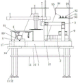
FIG. 1 is a schematic front view of the structure of the present invention;
FIG. 2 is a schematic top view of the structure of the present invention;
FIG. 3 is a schematic view of the first and second sewing portions of the present invention;
FIG. 4 is a schematic view of the X-axis slide rail, the Y-axis slide rail and the material moving mechanism of the present invention;
FIG. 5 is a schematic top view of the X-axis slide rail, the Y-axis slide rail and the material moving mechanism of the present invention;
FIG. 6 is a schematic view of a take-off mechanism of the present invention;
fig. 7 is a schematic view of the structure of the mounting frame of the present invention.
In the figure: 1. a machine platform; 10. a middle liner plate; 11. a partition plate; 12. a foot seat; 13. a support pillar; 14. a side liner plate; 15. a first groove; 16. a second groove; 17. a third groove; 2. a first sewing part; 3. a mounting frame; 30. a first connecting fixing plate; 31. a left support leg; 32. a first cross frame plate; 33. fastening a bolt; 34. a second connecting and fixing plate; 35. a right supporting leg; 4. a material taking mechanism; 40. a first linear slide rail; 41. a first slider; 42. a support plate; 43. a fixed block; 44. a second cross frame plate; 45. a second linear slide rail; 46. a third linear slide rail; 47. an intelligent electronic gripper; 48. a clamping jaw; 5. an X-axis slide rail; 50. an X-axis sliding sleeve; 6. a material moving mechanism; 60. mounting a plate; 61. a telescopic cylinder; 62. a mobile platform; 7. a Y-axis slide rail; 70. a Y-axis sliding sleeve; 8. a second sewing part; 80. overlock needles; 81. a control panel; 9. a wire frame structure; 90. a bobbin mounting plate; 91. a bobbin seat; 92. a bobbin; 93. fixing the rod; 94. a connecting rod; 95. a lead frame.
Detailed Description
The technical solutions in the embodiments of the present invention will be clearly and completely described below with reference to the drawings in the embodiments of the present invention, and it is obvious that the described embodiments are only a part of the embodiments of the present invention, and not all of the embodiments. All other embodiments, which can be derived by a person skilled in the art from the embodiments given herein without making any creative effort, shall fall within the protection scope of the present invention.
In a first embodiment, referring to fig. 1 to 7, the present invention provides a technical solution: the utility model provides an automatic bag cloth machine of copying, which comprises a worktable 1, mounting bracket 3, feeding agencies 4 and Y axle slide rail 7, two sets of mounting bracket 3 are installed to the up end right part of board 1, and install Y axle slide rail 7 between the left end of two sets of mounting bracket 3, sliding connection has X axle slide rail 5 on Y axle slide rail 7, and sliding connection has material moving mechanism 6 on X axle slide rail 5, feeding agencies 4 are installed to the up end front portion of board 1, second recess 16 has been seted up to the up end left side rear portion of board 1, and the up end left side front portion of board 1 installs feeding agencies 4.
When the automatic bag copying machine is used, firstly, a bag is placed in a designated copying area of a first sewing part 2, the bag is tidily flattened, the side end of the bag is copied by the first sewing part 2, after copying of the side end is finished, the bag material is placed on a moving platform 62 at the lower part of a material moving mechanism 6, the moving platform 62 is lifted, at the moment, an X-axis slide rail 5 moves backwards and properly on a Y-axis slide rail 7, the material moving mechanism 6 moves leftwards and properly on the X-axis slide rail 5, when the bag material moves to the front of a second sewing part 8, a telescopic cylinder 61 on the material moving mechanism 6 extends downwards and properly and straightly to drive the moving platform 62 to move downwards, at the moment, the bag material is copied by the second sewing part 8, after copying, first sliding blocks 41 at the bottom ends of supporting plates 42 at the left side and the right side of a material taking mechanism 4 move forwards on a first straight line slide rail 40, and the intelligent electronic gripper 47 starts to move downwards on the third linear sliding rail 46, so that the clamping jaws 48 clamp the bag and clamp the bag into the second groove 16, and the automatic bag taking-away work is completed.
In the invention, the first sewing part 2 is arranged in the first groove 15 formed in the middle of the right side of the upper end face of the machine table 1, the second sewing part 8 is arranged in the third groove 17 on the upper end face of the machine table 1, the first sewing part 2 and the second sewing part 8 are identical in structure arrangement, the first sewing part 2 is arranged for overlocking the side end of the bag, and the second sewing part 8 is arranged for overlocking the bottom end of the bag, so that overlocking is facilitated, and the use is rapid and convenient.
In the invention, two groups of mounting frames 3 are mounted on the right side of the upper end surface of the machine table 1, and the mounting frames 3 are mainly used for mounting and stabilizing the Y-axis slide rail 7, so that the Y-axis slide rail 7 and the equipment mounted on the Y-axis slide rail 7 can be safely and stably mounted and operated.
In a fourth embodiment, the first embodiment is further limited, in the present invention, the material taking mechanism 4 is configured to automatically take off the bag that is finished with the overlock, the left and right sides of the material taking mechanism 4 are symmetrically provided with the fixed blocks 43, the supporting plate 42, the first slider 41 and the first linear slide rail 40, and the first slider 41 is slidably connected to the first linear slide rail 40, so that the material taking mechanism 4 can move back and forth, so as to transport the bag from the material placing table 80 to the second groove 16.
Fifth embodiment, the fourth embodiment is further limited to the fifth embodiment, in the present invention, a second linear slide rail 45, a third linear slide rail 46, an intelligent electronic gripper 47, and a clamping jaw 48 are symmetrically arranged at two left and right sides of the lower end surface of the second cross frame plate 44 on the material taking mechanism 4, the upper end of the third linear slide rail 46 moves left and right on the second linear slide rail 45, and the intelligent electronic gripper 47 can move up and down on the third linear slide rail 46, so as to facilitate the clamping jaw 48 to clamp the bag.
In the invention, an X-axis slide rail 5 and a Y-axis slide rail 7 are respectively used as an X-axis slide rail structure and a Y-axis slide rail structure to facilitate changing the displacement of a material moving mechanism 6 on a horizontal plane, two groups of telescopic cylinders 61 are arranged below an installation plate 60 arranged on the side surface of the material moving mechanism 6, a moving platform 62 is arranged between the lower ends of the two groups of telescopic cylinders 61, the moving platform 62 is conveniently driven to move up and down through the telescopic movement of the telescopic cylinders 61 in the vertical direction, and the position of the moving platform 62 in a three-dimensional space is conveniently changed through the arrangement of the X-axis slide rail 5, the Y-axis slide rail 7 and the telescopic cylinders 61, so that bag materials are conveniently conveyed, the use is more flexible and convenient, and the labor cost is saved.
Seventh embodiment, the second embodiment is further limited to the second embodiment, in the present invention, the front end of the second sewing part 8 is provided with a overlock needle 80, and the rear part of the upper end of the second sewing part 8 is provided with a control panel 81, the second sewing part 8 can be directly controlled to normally operate through the control panel 81, so that the overlock needle 80 overlock the bottom end of the bag, and the first sewing part 2 and the second sewing part 8 are configured in the same structure, and the first sewing part 2 is configured to overlock the side end of the bag.
In an eighth embodiment, the first embodiment is further limited to the first embodiment, in the present invention, two sets of bobbin structures 9 are installed on the machine table 1, the two sets of bobbin structures 9 are respectively corresponding to the first sewing portion 2 and the second sewing portion 8 one by one and are used in cooperation with each other, a bobbin mounting plate 90 and a fixing rod 93 are respectively installed on the middle portion and the upper portion of the bobbin structure 9, a bobbin seat 91 installed on the bobbin mounting plate 90 is used for mounting a bobbin, and a connecting rod 94 and a lead frame 95 at the front end of the fixing rod 93 form a guiding structure of a binding line.
In the ninth embodiment, the first embodiment is further limited, in the invention, a middle pad 10 and a side pad 14 are arranged on the bottom surface of the machine table 1, and two groups of supporting columns 13 are fixed under the side pad 14, so that the machine table 1 can be conveniently supported for use, and the partition 11 arranged between the supporting columns 13 on both sides can reinforce the structures on both sides.
Although embodiments of the present invention have been shown and described, it will be appreciated by those skilled in the art that changes, modifications, substitutions and alterations can be made in these embodiments without departing from the principles and spirit of the invention, the scope of which is defined in the appended claims and their equivalents.
Claims (9)
1. The utility model provides an automatic bag cloth machine of copying, includes board (1), mounting bracket (3), feeding agencies (4) and Y axle slide rail (7), its characterized in that: the utility model discloses a sewing machine, including board (1), upper end face left side front-mounted of board (1) has two sets of mounting bracket (3), and installs Y axle slide rail (7) between the left end of two sets of mounting bracket (3), sliding connection has X axle slide rail (5) on Y axle slide rail (7), and sliding connection has material moving mechanism (6) on X axle slide rail (5), second sewing portion (8) are installed to the upper end face left side rear portion of board (1), the upper end face left side front-mounted of board (1) has feeding agencies (4).
2. The automatic bag copying machine according to claim 1, characterized in that: first recess (15) have been seted up at the up end right side middle part of board (1), and install first sewing portion (2) in first recess (15) to third recess (17) have been seted up at the up end left side rear portion of board (1), and second sewing portion (8) are located third recess (17).
3. The automatic bag copying machine according to claim 1, characterized in that: mounting bracket (3) are provided with first horizontal frame board (32), and both ends are fixed with left branch fagging (31) and right branch fagging (35) respectively about the lower terminal surface of first horizontal frame board (32) to install first connection fixed plate (30) through fastening bolt (33) between first horizontal frame board (32) and Y axle slide rail (7), install second connection fixed plate (34) through fastening bolt (33) between first horizontal frame board (32) and right branch fagging (35).
4. The automatic bag copying machine according to claim 1, characterized in that: the upper end of feeding agencies (4) is provided with second cross slab (44), both ends head all is provided with fixed block (43) about second cross slab (44), and all is fixed with backup pad (42) under every group fixed block (43), and the bottom of backup pad (42) is provided with first slider (41), first slider (41) sliding connection of every group is on first straight line slide rail (40), and two sets of first straight line slide rails (40) of feeding agencies (4) below all install on the up end of board (1), and two sets of first straight line slide rails (40) are located the left and right sides both sides of second recess (16) respectively.
5. The automatic bag copying machine according to claim 4, characterized in that: the lower terminal surface left part and the right part of second horizontal frame plate (44) all are provided with second linear slide rail (45), and sliding connection has third linear slide rail (46) down second linear slide rail (45) to sliding connection has intelligent electron holder (47) on third linear slide rail (46), and is provided with clamping jaw (48) under intelligent electron holder (47), and installs infrared inductor on intelligent electron holder (47).
6. The automatic bag copying machine according to claim 1, characterized in that: sliding connection has Y axle sliding sleeve (70) on Y axle slide rail (7), and the lower terminal surface right part in X axle slide rail (5) is fixed to the upper end of Y axle sliding sleeve (70), and sliding connection has X axle sliding sleeve (50) on X axle slide rail (5), and the upper end of X axle sliding sleeve (50) is fixed under material moving mechanism (6), and install mounting panel (60) on the leading flank of material moving mechanism (6), install two sets of telescopic cylinder (61) under mounting panel (60), and install moving platform (62) between the lower extreme of two sets of telescopic cylinder (61).
7. The automatic bag copying machine according to claim 2, characterized in that: a overlock needle (80) is installed at the lower part of the front end of the second sewing part (8), a control panel (81) is arranged at the rear part of the upper end of the second sewing part (8), and the first sewing part (2) and the second sewing part (8) are identical in structural arrangement.
8. The automatic bag copying machine according to claim 1, characterized in that: a set of line frame structure (9) is all installed to the up end right part front side and the middle part rear side of board (1), and two sets of line frame structure (9) respectively with first sewing portion (2), the setting of cooperateing between second sewing portion (8), the lower extreme vertical fixation of line frame structure (9) is on board (1), the mid-mounting of line frame structure (9) has bobbin mounting panel (90), install three sets of bobbin bases (91) on bobbin mounting panel (90), all overlap on every set of bobbin base (91) and have put a set of bobbin (92), and bobbin (92) are for dismantling the structure, dead lever (93) are installed on the upper portion of line frame structure (9), are fixed with connecting rod (94) under the front end of dead lever (93), the lower extreme of connecting rod (94) is provided with wire frame (95).
9. The automatic bag copying machine according to claim 1, characterized in that: the lower end face middle part of board (1) is provided with well backing plate (10), and the lower end face left side and the right side of board (1) all are provided with three group's limit backing plates (14) to all install two sets of support columns (13) under every group limit backing plate (14), the lower extreme of support column (13) is provided with foot stool (12), and installs baffle (11) between support column (13) of the left and right sides below board (1).
Priority Applications (1)
| Application Number | Priority Date | Filing Date | Title |
|---|---|---|---|
| CN202110519849.XA CN113944013A (en) | 2021-05-13 | 2021-05-13 | Automatic bag cloth copying machine |
Applications Claiming Priority (1)
| Application Number | Priority Date | Filing Date | Title |
|---|---|---|---|
| CN202110519849.XA CN113944013A (en) | 2021-05-13 | 2021-05-13 | Automatic bag cloth copying machine |
Publications (1)
| Publication Number | Publication Date |
|---|---|
| CN113944013A true CN113944013A (en) | 2022-01-18 |
Family
ID=79327336
Family Applications (1)
| Application Number | Title | Priority Date | Filing Date |
|---|---|---|---|
| CN202110519849.XA Pending CN113944013A (en) | 2021-05-13 | 2021-05-13 | Automatic bag cloth copying machine |
Country Status (1)
| Country | Link |
|---|---|
| CN (1) | CN113944013A (en) |
Cited By (1)
| Publication number | Priority date | Publication date | Assignee | Title |
|---|---|---|---|---|
| CN114575046A (en) * | 2022-02-23 | 2022-06-03 | 申洲针织(安徽)有限公司 | Automatic overlock double-needle linear edge sewing auxiliary device and operation method thereof |
-
2021
- 2021-05-13 CN CN202110519849.XA patent/CN113944013A/en active Pending
Cited By (1)
| Publication number | Priority date | Publication date | Assignee | Title |
|---|---|---|---|---|
| CN114575046A (en) * | 2022-02-23 | 2022-06-03 | 申洲针织(安徽)有限公司 | Automatic overlock double-needle linear edge sewing auxiliary device and operation method thereof |
Similar Documents
| Publication | Publication Date | Title |
|---|---|---|
| CN111575926A (en) | Bag opening machine for processing pocket opening of clothes | |
| CN113944013A (en) | Automatic bag cloth copying machine | |
| CN207582082U (en) | A kind of full-automatic sewing machine | |
| CN109440305A (en) | A kind of automatic sewing unit | |
| CN108060508A (en) | A kind of flange fixing installation on sewing machine | |
| CN215103865U (en) | Automatic bag cloth copying machine | |
| CN202671835U (en) | Bra buckle-joining machine | |
| CN107268195A (en) | The automatic feeding method of template automatic positioning mechanism, template machine and template machine | |
| CN110485068A (en) | Shopping bag bracelet tailoring machine | |
| CN112962227B (en) | Automatic cloth guide device for intelligent sewing machine and working method thereof | |
| CN210826688U (en) | Gold sheet, lamination and tube bead integrated device of computer embroidery machine | |
| CN211446134U (en) | Trilateral automatic synchronization sewing equipment | |
| CN113463281A (en) | Overedger for textile fabric processing | |
| CN218711327U (en) | Double-needle flat-seam sewing machine for making non-woven fabric bag | |
| CN213061278U (en) | Computer pattern sewing machine for shoemaking | |
| CN209602754U (en) | A kind of automatic sewing unit | |
| CN217324539U (en) | Edge sewing mechanism for knitted fabric | |
| CN213113809U (en) | Trousers waist noose sewing machine | |
| CN113463282A (en) | Automatic overlock machine for strip-shaped bandage | |
| CN219793369U (en) | Cloth edge bonding machine | |
| JP3568187B2 (en) | Automatic sewing device for sword rags | |
| CN221117867U (en) | Semi-automatic frock suitable for sewing of two needle decorative lines | |
| CN219991880U (en) | Quilt material automatic feeding quilting machine | |
| CN215628959U (en) | Novel folding machine capable of automatically adjusting curtain pleat depth | |
| CN219470394U (en) | Quilting machine |
Legal Events
| Date | Code | Title | Description |
|---|---|---|---|
| PB01 | Publication | ||
| PB01 | Publication | ||
| SE01 | Entry into force of request for substantive examination | ||
| SE01 | Entry into force of request for substantive examination |