CN113846664A - Continuous soil-taking and sinking machine for non-drainage open caisson - Google Patents
Continuous soil-taking and sinking machine for non-drainage open caisson Download PDFInfo
- Publication number
- CN113846664A CN113846664A CN202110895227.7A CN202110895227A CN113846664A CN 113846664 A CN113846664 A CN 113846664A CN 202110895227 A CN202110895227 A CN 202110895227A CN 113846664 A CN113846664 A CN 113846664A
- Authority
- CN
- China
- Prior art keywords
- pressure water
- open caisson
- oil cylinder
- center
- frame
- Prior art date
- Legal status (The legal status is an assumption and is not a legal conclusion. Google has not performed a legal analysis and makes no representation as to the accuracy of the status listed.)
- Granted
Links
Images
Classifications
-
- E—FIXED CONSTRUCTIONS
- E02—HYDRAULIC ENGINEERING; FOUNDATIONS; SOIL SHIFTING
- E02D—FOUNDATIONS; EXCAVATIONS; EMBANKMENTS; UNDERGROUND OR UNDERWATER STRUCTURES
- E02D23/00—Caissons; Construction or placing of caissons
- E02D23/08—Lowering or sinking caissons
Landscapes
- Engineering & Computer Science (AREA)
- Life Sciences & Earth Sciences (AREA)
- General Life Sciences & Earth Sciences (AREA)
- Mining & Mineral Resources (AREA)
- Paleontology (AREA)
- Civil Engineering (AREA)
- General Engineering & Computer Science (AREA)
- Structural Engineering (AREA)
- Earth Drilling (AREA)
Abstract
The invention relates to a machine tool for continuously taking earth and sinking a non-drainage open caisson, which is provided with an H-shaped beam frame arranged on a prefabricated bearing platform on the inner wall of the open caisson; the center of the H-shaped beam frame is provided with a reciprocating rotating assembly, the center of the reciprocating rotating assembly is provided with a rotatable hollow cylinder, the lower end surface of the hollow cylinder is fixedly connected with three uniformly distributed main arm frames through a cylinder frame, the lower part of each main arm frame is provided with a high-pressure water spraying assembly, and the high-pressure water spraying assembly can rotate and translate at the same time and is used for breaking the ground in the central area of the open caisson; the front end of the main arm support is provided with a front arm which can swing up and down, and the foremost end of the front arm is provided with a high-pressure water spraying assembly which can stretch and swing at the same time and is used for breaking soil in an open caisson cutting edge area; a main suction dredge pump is arranged in the center of the circular frame member and is connected with a mud sedimentation tank outside the open caisson through a mud discharge pipe; each high-pressure water spraying assembly is connected with a high-pressure water pump and a clean water tank through a high-pressure water pipe; the soil body is cut and washed by high-pressure water to form slurry, and the slurry is sucked by a mud suction pump and discharged to the outside of a well.
Description
Technical Field
The invention relates to a tool device for continuously taking earth to sink an open caisson in open caisson construction.
Background
The open caisson is a well tubular structure, and the sinking construction is that the open caisson is sunk to the designed elevation after overcoming the frictional resistance between the well wall and the soil body on the outer side by the self gravity through the soil digging in the open caisson, and the open caisson becomes the foundation of the building structure through concrete bottom sealing.
At present, buildings, roads, comprehensive pipelines and underground building structures in cities have strict settlement control, and if a dry open caisson sinking construction method for precipitation outside wells is adopted, the precipitation period is long, and the influence on the stability of peripheral soil bodies is large; and the sinking construction method of the open caisson without drainage is adopted, so that the underwater construction of divers is often adopted, but the efficiency is low, or the grab bucket underwater mud taking is difficult to touch the blade foot area.
Therefore, the settlement is to be solved, and in the sinking construction process of the non-drainage open caisson, the soil can be uniformly and continuously taken from the area including the blade foot inside the open caisson, so that the open caisson sinks stably.
Disclosure of Invention
In order to solve the technical problems, the invention aims to provide a tool for continuously taking out soil and sinking a non-drainage open caisson, which is particularly suitable for uniformly and continuously breaking soil, taking out soil and discharging the soil from the bottom surface of the non-drainage open caisson underwater, wherein the process is carried out in a layered manner, so that the open caisson sinks stably.
In order to achieve the purpose, the technical scheme of the invention is as follows: a continuous soil-taking and sinking machine for a non-drainage open caisson is provided with an H-shaped beam frame arranged on a prefabricated bearing platform on the inner wall of the open caisson; the center of the H-shaped beam frame is provided with a reciprocating rotating assembly, the center of the reciprocating rotating assembly is provided with a rotatable hollow cylinder, the lower end face of the hollow cylinder is fixedly connected with three uniformly distributed main arm frames through a cylindrical frame, the lower part of each main arm frame is provided with a high-pressure water spraying assembly, and the high-pressure water spraying assembly can rotate and translate at the same time and is used for breaking the ground in the central area of the open caisson; the front end of the main arm support is provided with a front arm which can swing up and down, and the foremost end of the front arm is provided with a high-pressure water spraying assembly which can stretch and swing at the same time and is used for breaking the soil in the open caisson cutting edge area; a main suction dredge pump is arranged in the center of the circular frame member and is connected with a mud sedimentation tank outside the open caisson through a mud discharge pipe; each high-pressure water spraying assembly is connected with a high-pressure water pump and a clean water tank through a high-pressure water pipe; the soil body is cut and washed by high-pressure water to form slurry, the slurry is sucked by a mud suction pump and discharged to the outside of the well, the reciprocating swing of the main arm support is combined with the motion of each high-pressure water spraying assembly, so that the high-pressure water spraying area can be moved to any area in the well, the effect of uniformly taking soil in a layered mode is achieved, and the open caisson can sink stably.
Furthermore, the H-shaped beam frame consists of beam arms and a central seat and is spliced by bolts; the beam arm is in a box beam structure, an oil cylinder is arranged in the beam arm, and a piston rod of the oil cylinder extends outwards to be capable of propping against a well wall, so that the H-shaped beam frame is stable.
Furthermore, the center seat is composed of a center cylinder, a conical copper sleeve, a center seat body, an end cover and a sealing element, the outer cylindrical surface of the center cylinder is provided with a conical surface structure matched with the conical copper sleeve, the center cylinder and the conical copper sleeve are combined and then installed at the matched conical surface of the center seat body, and the center cylinder can automatically center when rotating in a reciprocating mode through sliding fit of the conical surfaces, so that the center cylinder moves stably.
Further, a cylindrical frame is arranged on the end face of the lower flange of the central cylinder and is of a circular pipe truss structure, a main dredge pump is arranged at the center of the cylindrical frame, and an auxiliary dredge pump is arranged on the outer side of the cylindrical frame; the central cylinder is of a hollow steel pipe structure, the lower end face of the central cylinder is provided with a connecting flange, and the outer cylindrical surface at the upper part of the central cylinder is symmetrically provided with an extending arm; the inside is the passageway of mud pipe, high pressure water pipe and cable, arranges corresponding mounting.
Further, the main arm frame is installed on the outer side of the cylindrical frame, and the finished product is arranged in a triangular mode and is of a circular tube truss structure.
Further, a swing oil cylinder of a high-pressure water spraying assembly of the main arm frame is arranged at the central axis, a pair of double-acting double-piston-rod oil cylinders is arranged on a rotary flange plate of the main arm frame, a high-pressure water spraying rod is arranged at the lower part of each piston rod, a plurality of high-pressure water spraying nozzles are arranged at the lower part of each high-pressure water spraying rod and form an inclined angle with the ground, and the preferred 45-degree angle is towards the center; when the piston rod moves, the water spray nozzle group is driven to move, and the water spray nozzle group can move in the same direction or move in opposite directions; the swinging oil cylinder rotates to drive the oil cylinder to rotate so as to drive the water spray nozzle group to rotate, and soil in the central area can be washed.
Furthermore, the reciprocating rotation assembly is composed of an oil cylinder and push rods, the oil cylinder and the push rods are symmetrically arranged on two sides of the central column in groups, one end of each push rod is hinged with a piston rod of the oil cylinder, and the other end of each push rod is hinged with an extending arm of the central column; when the piston rod on one side extends out, the push rod is pushed to move towards the direction of the central column, and the push rod pushes the central column to rotate around the axis of the central column in the anticlockwise direction; and when the stroke is finished, the piston rod retracts, the push rod is pulled to move away from the central column, and the push rod pulls the central column to rotate clockwise around the axis of the central column.
Furthermore, the front arm is positioned at the front end of the main arm frame and is arranged on a rotary flange plate of a swing oil cylinder at the front end of the main arm frame, and the swing oil cylinder rotates to drive the front arm to swing up and down; the front end of the front arm is provided with a swing oil cylinder, and a rotary flange of the swing oil cylinder is provided with a high-pressure water nozzle; the swing oil cylinder rotates to drive the high-pressure water spray nozzle to swing, so that soil bodies in the blade foot area are washed.
Furthermore, the high-pressure nozzle is provided with a bypass mud suction port, and the high-pressure nozzle sucks and sprays out the mixed external soil particles under the siphon effect of high-pressure water of the main pipeline, so that the kinetic energy of water spraying is improved, the soil breaking effect is improved, and the efficiency is improved.
Furthermore, each telescopic oil cylinder is provided with a stroke sensor, each swing oil cylinder is provided with an angle sensor, attitude data can be transmitted in a control console in real time during work, and constructors can monitor or move a water spraying area according to the attitude data.
The invention has the beneficial effects that:
(1) the device is arranged on the open caisson and sinks along with the open caisson, so that underwater construction by divers is not needed, and danger of constructors is avoided.
(2) The invention adopts high-pressure water to break soil, the mud is discharged by the mud suction pump, the construction efficiency is high, the soil taking is uniform, and the problem that the grab bucket is difficult to grab soil underwater is avoided.
(3) The invention is suitable for the construction of the open caisson without water drainage, has little influence on the stability of the surrounding soil body and reduces the sedimentation risk of the surrounding buildings.
Drawings
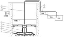
FIG. 1 is a schematic view of the general layout of the continuous earth-taking and sinking implement of the invention for a non-draining open caisson;
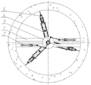
FIG. 2 is a horizontal schematic diagram of the overall arrangement of the continuous earth-taking and sinking implement of the non-draining open caisson of the present invention;
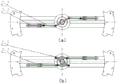
FIG. 3 is a schematic view of the motion of the reciprocating pivoting assembly of the present invention;
wherein: (a) retracting the oil cylinder, (b) retracting the oil cylinder;
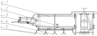
FIG. 4 is a schematic structural diagram of the main boom of the present invention;
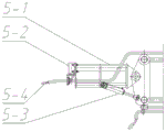
fig. 5 is a schematic view of the structure of the forearm of the invention.
Detailed Description
The following describes embodiments of the present invention with reference to the drawings and examples.
As shown in fig. 1 and 2, the continuous soil-taking and sinking implement of the non-drainage open caisson of the invention mainly comprises: the device comprises an H-shaped beam frame 1, a reciprocating rotation assembly 2, a cylindrical frame 3, a main arm frame 4, a front arm 5, a main suction dredge pump 6, a high-pressure water pump 7, a hydraulic pump station 8, a console 9, a mud discharge pipe 10, a high-pressure water pipe 11 and a cable 12.
The H-shaped beam frame 1 is arranged on a prefabricated bearing platform on the inner wall of the open caisson; the center of the H-shaped beam frame 1 is provided with a reciprocating rotation assembly 2, the center of the reciprocating rotation assembly 2 is provided with a rotatable hollow cylinder, the lower end face of the cylinder is fixedly connected with a cylinder frame 3, and the outer ring of the cylinder frame 3 is provided with three main arm supports 4 which are arranged in an equal distribution manner and are of a truss structure; the lower part of each main arm support 4 is provided with a high-pressure water spraying assembly which can rotate and translate at the same time and is used for breaking the ground in the central area of the open caisson; the front end of the main arm support 4 is provided with a front arm 5 which can swing up and down, and the foremost end of the front arm 5 is provided with a high-pressure water spraying component which can extend and swing at the same time. The main suction dredge pump 6 is arranged in the center of the circular frame member, and the main suction dredge pump 6 is connected with a mud sedimentation tank outside the open caisson through a mud discharge pipe 10. Each high-pressure water spraying assembly is connected with a high-pressure water pump 7 through a high-pressure water pipe 11. The high-pressure water pipe 11, the sludge discharge pipe 10, the hydraulic pipeline and the control cable penetrate out of the hollow cylinder. The cable 12 is respectively connected with each pump body, the hydraulic pump station 8 and the console 9. The soil body is cut, washed and the like by using high-pressure water to form slurry, then the slurry is sucked by the mud suction pump 6 and discharged to the outside of the well, the reciprocating swing of the main arm frame is combined with the motion of each water spraying assembly, so that the high-pressure water spraying area can be moved to any area in the well, the effect of uniformly taking soil in a layered mode is achieved, and the open caisson can sink stably.
The H-shaped beam frame 1 comprises beam arms, a center seat and a center column. The beam arm is in a box beam structure, an oil cylinder is arranged in the beam arm, and a piston rod of the oil cylinder extends outwards to be capable of propping against a well wall, so that the H-shaped beam frame is stable. The central seat consists of a central cylinder, a conical copper sleeve, a central seat body, an end cover and a sealing element, wherein the outer cylindrical surface of the central cylinder is provided with a conical surface structure matched with the conical copper sleeve, the central cylinder and the conical copper sleeve are combined and then installed at the matched conical surface of the central seat body, and the central cylinder can automatically center and stably move when rotating in a reciprocating manner through the sliding fit of the conical surfaces. The end face of the flange below the central column is provided with a cylindrical frame which is of a circular tube truss structure, the center of the cylindrical frame is provided with a main dredge pump 6, and the outer side of the cylindrical frame is provided with an auxiliary dredge pump. The central column is of a hollow steel pipe structure, the lower end face of the central column is provided with a connecting flange, and the outer cylindrical surface at the upper part of the central column is symmetrically provided with extending arms; the inside is a passage of a mud discharging pipe 10, a high-pressure water pipe 11 and a cable 12, and corresponding fixing pieces are arranged.
As shown in fig. 3 (a) and (b), the reciprocating rotary assembly 2 includes a cylinder 2-1 and a push rod 2-2. The push rods 2-2 are symmetrically arranged at two sides of the central column in groups, one end of each push rod 2-2 is hinged with a piston rod of the oil cylinder 2-1, and the other end of each push rod is hinged with an extending arm of the central column; when the piston rod on one side extends out, the push rod 2-2 is pushed to move towards the central column, and the push rod 2-2 pushes the central column to rotate around the axis of the central column in the anticlockwise direction; and when the stroke is finished, the piston rod retracts, the push rod 2-2 is pulled to move away from the central column, and the push rod 2-2 pulls the central column to rotate clockwise around the axis of the central column.
As shown in fig. 4, the main arm frame 4 comprises a main arm truss 4-1, a swing oil cylinder 4-2, a telescopic oil cylinder 4-3, a water spray rod 4-4 and a water spray nozzle 4-5. The main arm support 4 is arranged on the outer side of the cylindrical frame, and the finished product is in a shape of a Chinese character 'sanqu' and is in a circular tube truss structure. A swing oil cylinder 4-2 of a high-pressure water spraying assembly of the main arm frame is arranged at the central axis, a pair of double-acting double-piston-rod oil cylinders 4-3 is arranged on a rotary flange plate of the main arm frame, a high-pressure water spraying rod 4-4 is arranged at the lower part of each piston rod, a plurality of high-pressure water spraying nozzles 4-5 are arranged at the lower part of the high-pressure water spraying rod 4-4 and form an inclined angle with the ground, preferably a 45-degree angle, and face the center; when the piston rod moves, the 4-5 groups of the water nozzles are driven to move, and the water nozzles can move in the same direction or move in opposite directions; the swinging oil cylinder 4-2 rotates to drive the oil cylinder 4-3 to rotate so as to drive the water spray rod 4-4 and the water spray nozzle 4-5 group to rotate, and soil in the central area can be washed.
As shown in figure 5, the front arm 5 comprises a front arm truss 5-1, a swing oil cylinder 5-2, a telescopic oil cylinder 5-3 and a high-pressure water nozzle 5-4. The front arm 5 is positioned at the front end of the main arm support 4, is arranged on a rotary flange of a swing oil cylinder 5-2 at the front end of the main arm support 4, and drives the front arm 5 to swing up and down through the rotation of the swing oil cylinder 5-2; the front end of the front arm 5 is provided with a swing oil cylinder 5-2, and a rotary flange of the swing oil cylinder 5-2 is provided with a high-pressure water nozzle 5-4; the swing oil cylinder 5-2 rotates to drive the high-pressure water nozzle 5-4 to swing, and soil bodies in the blade foot area are washed. The high-pressure nozzles 5-4 are provided with bypass mud suction ports, and suck and mix external soil particles under the siphon effect of high-pressure water of the main pipeline and then spray the mixture, so that the kinetic energy of water spraying is improved, the soil breaking effect is improved, and the efficiency is improved.
Each telescopic oil cylinder is provided with a stroke sensor, each swing oil cylinder is provided with an angle sensor, attitude data can be transmitted in a control console in real time during work, and constructors can monitor or move a water spraying area according to the attitude data.
And (5) performing test operation, wherein each high-pressure water nozzle sprays water normally, and the standard pressure value is qualified. Each oil cylinder stretches normally and rotates and swings normally. At this time, the device is normally operated, water injection is started to the elevation in the well, the high-pressure water pump 7 supplies water to each nozzle, and the device sequentially operates under the program control of the console 9:
1) the swing oil cylinder 4-2 of the main arm support 4 rotates to drive the pair of telescopic oil cylinders 4-3 to swing forward and backward by 180 degrees, and the water spray rod 4-4 and the water spray nozzle 4-5 are driven to swing forward and backward by 180 degrees. Meanwhile, the telescopic oil cylinder 4-3 is telescopic to drive the water spray rod, and the water spray nozzle moves to wash the soil body in the central area.
2) The swing oil cylinder 5-2 of the front arm 5 rotates to drive the water spray nozzle to swing up and down by 30 degrees, so as to scour soil bodies in the blade foot area.
3) When a piston rod of an oil cylinder of the reciprocating rotation assembly 2 extends out, the push rod 2-2 is pushed to move towards the direction of the central column, the push rod 2-2 pushes the extending arm of the central column to rotate around the axis of the extending arm in the anticlockwise direction, and the central column drives the main arm support 4 to rotate in the anticlockwise direction; and when the stroke is finished, the piston rod of the oil cylinder retracts, the push rod 2-2 is pulled to move away from the central column, the push rod 2-2 pulls the central column to rotate clockwise around the axis of the central column, and the central column drives the main arm support 4 to rotate anticlockwise. The process is circulated to drive all the water nozzles to wash any area in the sinking well, and the layered soil breaking process is completed.
4) The main suction dredge 6 discharges the slurry out of the open caisson into a slurry tank in the process, and the slurry discharge amount is determined according to the sinking speed of the open caisson.
Claims (10)
1. The utility model provides a continuous geotome that fetches earth of open caisson does not drain sinks which characterized in that: the H-shaped beam frame is arranged on a prefabricated bearing platform on the inner wall of the open caisson; the center of the H-shaped beam frame is provided with a reciprocating rotating assembly, the center of the reciprocating rotating assembly is provided with a rotatable hollow cylinder, the lower end face of the hollow cylinder is fixedly connected with three uniformly distributed main arm frames through a cylindrical frame, the lower part of each main arm frame is provided with a high-pressure water spraying assembly, and the high-pressure water spraying assembly can rotate and translate at the same time and is used for breaking the ground in the central area of the open caisson; the front end of the main arm support is provided with a front arm which can swing up and down, and the foremost end of the front arm is provided with a high-pressure water spraying assembly which can stretch and swing at the same time and is used for breaking the soil in the open caisson cutting edge area; a main suction dredge pump is arranged in the center of the circular frame member and is connected with a mud sedimentation tank outside the open caisson through a mud discharge pipe; each high-pressure water spraying assembly is connected with a high-pressure water pump and a clean water tank through a high-pressure water pipe; the soil body is cut and washed by high-pressure water to form slurry, the slurry is sucked by a mud suction pump and discharged to the outside of the well, the reciprocating swing of the main arm support is combined with the motion of each high-pressure water spraying assembly, so that the high-pressure water spraying area can be moved to any area in the well, the effect of uniformly taking soil in a layered mode is achieved, and the open caisson can sink stably.
2. The tool for continuous earth taking and sinking of the undrained open caisson according to claim 1, wherein: the H-shaped beam frame consists of beam arms and a central seat and is spliced by bolts; the beam arm is of a box beam structure, an oil cylinder is arranged in the beam arm, and a piston rod of the oil cylinder extends outwards to be capable of propping against a well wall, so that the H-shaped beam frame is stable.
3. The tool for continuous earth taking and sinking of the undrained open caisson according to claim 2, wherein: the center seat is composed of a center cylinder, a conical copper sleeve, a center seat body, an end cover and a sealing element, the outer cylindrical surface of the center cylinder is provided with a conical surface structure matched with the conical copper sleeve, the center cylinder and the conical copper sleeve are combined and then installed on the matched conical surface of the center seat body, and the center cylinder can automatically center and stably move when rotating in a reciprocating mode through sliding fit of the conical surfaces.
4. A tool for continuous earth extraction and sinking of a non-draining open caisson according to claim 3, wherein: a cylindrical frame is arranged on the end face of the lower flange of the central cylinder, a main dredge pump is arranged in the center of the cylindrical frame, and an auxiliary dredge pump is arranged on the outer side of the cylindrical frame; the central cylinder is of a hollow steel pipe structure, the lower end face of the central cylinder is provided with a connecting flange, and the outer cylindrical surface at the upper part of the central cylinder is symmetrically provided with an extending arm; the inside is the passageway of mud pipe, high pressure water pipe and cable, arranges corresponding mounting.
5. The tool for continuous earth taking and sinking of the undrained open caisson according to claim 4, wherein: the main arm support is arranged on the outer side of the cylindrical frame, and the finished product is in a shape of a Chinese character 'sanqu' and is of a circular tube truss structure.
6. The tool for continuous earth taking and sinking of the undrained open caisson according to claim 1, wherein: the swing oil cylinder of the high-pressure water spraying assembly of the main arm frame is arranged at the central axis, a pair of double-acting double-piston-rod oil cylinders is arranged on a rotary flange plate of the main arm frame, a high-pressure water spraying rod piece is arranged at the lower part of each piston rod, a plurality of high-pressure water spraying nozzles are arranged at the lower part of each high-pressure water spraying rod piece and form an inclined angle with the ground, and the preferred 45-degree angle is towards the center; when the piston rod moves, the water spray nozzle group is driven to move, and the water spray nozzle group can move in the same direction or move in opposite directions; the swinging oil cylinder rotates to drive the oil cylinder to rotate so as to drive the water spray nozzle group to rotate, and soil in the central area can be washed.
7. The tool for continuous earth taking and sinking of the undrained open caisson according to claim 1, wherein: the reciprocating rotation assembly is composed of an oil cylinder and push rods, the reciprocating rotation assembly is symmetrically arranged on two sides of the central column in groups, one end of each push rod is hinged with a piston rod of the oil cylinder, and the other end of each push rod is hinged with an extending arm of the central column; when the piston rod on one side extends out, the push rod is pushed to move towards the direction of the central column, and the push rod pushes the central column to rotate around the axis of the central column in the anticlockwise direction; and when the stroke is finished, the piston rod retracts, the push rod is pulled to move away from the central column, and the push rod pulls the central column to rotate clockwise around the axis of the central column.
8. The tool for continuous earth taking and sinking of the undrained open caisson according to claim 1, wherein: the front arm is positioned at the front end of the main arm frame, is arranged on a rotary flange of a swing oil cylinder at the front end of the main arm frame, and is driven to swing up and down through the rotation of the swing oil cylinder; the front end of the front arm is provided with a swing oil cylinder, and a rotary flange of the swing oil cylinder is provided with a high-pressure water nozzle; the swing oil cylinder rotates to drive the high-pressure water spray nozzle to swing, so that soil bodies in the blade foot area are washed.
9. The tool for continuous earth taking and sinking of the undrained open caisson according to claim 1, wherein: high pressure nozzle among the high pressure water spray subassembly has the bypass and inhales mud mouth, inhales under the siphon effect of its main line high pressure water and gets outside earth particle and mix the back blowout, improves the kinetic energy of water spray to promote the effect of breaking ground, raise the efficiency.
10. The tool for continuous earth taking and sinking of the undrained open caisson according to any one of claims 2 to 8, wherein: the telescopic oil cylinder is provided with a stroke sensor, the swing oil cylinder is provided with an angle sensor, attitude data can be transmitted in a control console in real time during work, and constructors can monitor or move a water spraying area accordingly.
Priority Applications (1)
| Application Number | Priority Date | Filing Date | Title |
|---|---|---|---|
| CN202110895227.7A CN113846664B (en) | 2021-08-05 | 2021-08-05 | Continuous soil-taking and sinking machine for non-drainage open caisson |
Applications Claiming Priority (1)
| Application Number | Priority Date | Filing Date | Title |
|---|---|---|---|
| CN202110895227.7A CN113846664B (en) | 2021-08-05 | 2021-08-05 | Continuous soil-taking and sinking machine for non-drainage open caisson |
Publications (2)
| Publication Number | Publication Date |
|---|---|
| CN113846664A true CN113846664A (en) | 2021-12-28 |
| CN113846664B CN113846664B (en) | 2023-03-10 |
Family
ID=78975463
Family Applications (1)
| Application Number | Title | Priority Date | Filing Date |
|---|---|---|---|
| CN202110895227.7A Active CN113846664B (en) | 2021-08-05 | 2021-08-05 | Continuous soil-taking and sinking machine for non-drainage open caisson |
Country Status (1)
| Country | Link |
|---|---|
| CN (1) | CN113846664B (en) |
Cited By (1)
| Publication number | Priority date | Publication date | Assignee | Title |
|---|---|---|---|---|
| CN114737591A (en) * | 2022-04-12 | 2022-07-12 | 交通运输部上海打捞局 | Cutter-suction type end plate auxiliary sinking system suitable for box-type end plate |
Citations (10)
| Publication number | Priority date | Publication date | Assignee | Title |
|---|---|---|---|---|
| JPS55152221A (en) * | 1979-05-17 | 1980-11-27 | Taiho Kensetsu Kk | Sinking method of caisson |
| CN1150210A (en) * | 1995-11-15 | 1997-05-21 | 阎林森 | Sealing shaft sinking method |
| JP2001020655A (en) * | 1999-07-09 | 2001-01-23 | Hitachi Constr Mach Co Ltd | Shaft excavating method and shaft excavator |
| CN201896317U (en) * | 2010-12-23 | 2011-07-13 | 浙江环宇建设集团有限公司 | Construction device for complex soil sinking open caisson by undrained dredging |
| CN106168033A (en) * | 2016-08-09 | 2016-11-30 | 岩土科技股份有限公司 | A kind of vertical mud and water balance constructing device |
| CN108360544A (en) * | 2018-03-10 | 2018-08-03 | 杨素钦 | A kind of automatic sinking device of open caisson and construction method |
| CN212223929U (en) * | 2020-05-09 | 2020-12-25 | 核工业井巷建设集团有限公司 | Flushing and sucking device for non-drainage sinking construction process of open caisson |
| CN112252349A (en) * | 2020-09-11 | 2021-01-22 | 北京市市政二建设工程有限责任公司 | Sinking construction method without drainage for open caisson |
| CN112983429A (en) * | 2021-04-15 | 2021-06-18 | 北京中岩智泊科技有限公司 | Open caisson heading machine |
| CN113047328A (en) * | 2021-03-31 | 2021-06-29 | 广州市如云网络科技有限公司 | Water conservancy is towards sinking open caisson construction equipment |
-
2021
- 2021-08-05 CN CN202110895227.7A patent/CN113846664B/en active Active
Patent Citations (10)
| Publication number | Priority date | Publication date | Assignee | Title |
|---|---|---|---|---|
| JPS55152221A (en) * | 1979-05-17 | 1980-11-27 | Taiho Kensetsu Kk | Sinking method of caisson |
| CN1150210A (en) * | 1995-11-15 | 1997-05-21 | 阎林森 | Sealing shaft sinking method |
| JP2001020655A (en) * | 1999-07-09 | 2001-01-23 | Hitachi Constr Mach Co Ltd | Shaft excavating method and shaft excavator |
| CN201896317U (en) * | 2010-12-23 | 2011-07-13 | 浙江环宇建设集团有限公司 | Construction device for complex soil sinking open caisson by undrained dredging |
| CN106168033A (en) * | 2016-08-09 | 2016-11-30 | 岩土科技股份有限公司 | A kind of vertical mud and water balance constructing device |
| CN108360544A (en) * | 2018-03-10 | 2018-08-03 | 杨素钦 | A kind of automatic sinking device of open caisson and construction method |
| CN212223929U (en) * | 2020-05-09 | 2020-12-25 | 核工业井巷建设集团有限公司 | Flushing and sucking device for non-drainage sinking construction process of open caisson |
| CN112252349A (en) * | 2020-09-11 | 2021-01-22 | 北京市市政二建设工程有限责任公司 | Sinking construction method without drainage for open caisson |
| CN113047328A (en) * | 2021-03-31 | 2021-06-29 | 广州市如云网络科技有限公司 | Water conservancy is towards sinking open caisson construction equipment |
| CN112983429A (en) * | 2021-04-15 | 2021-06-18 | 北京中岩智泊科技有限公司 | Open caisson heading machine |
Cited By (1)
| Publication number | Priority date | Publication date | Assignee | Title |
|---|---|---|---|---|
| CN114737591A (en) * | 2022-04-12 | 2022-07-12 | 交通运输部上海打捞局 | Cutter-suction type end plate auxiliary sinking system suitable for box-type end plate |
Also Published As
| Publication number | Publication date |
|---|---|
| CN113846664B (en) | 2023-03-10 |
Similar Documents
| Publication | Publication Date | Title |
|---|---|---|
| CN212223929U (en) | Flushing and sucking device for non-drainage sinking construction process of open caisson | |
| CN106168033B (en) | A kind of vertical mud and water balance constructing device | |
| CN109653682A (en) | Bore the adjustable drill bit of diameter and hole digging machine | |
| CN109183803A (en) | A kind of deep basal pit adverse construction method device and construction method | |
| CN113846664B (en) | Continuous soil-taking and sinking machine for non-drainage open caisson | |
| CN113482140B (en) | Municipal works sewer desilting device | |
| CN112177081B (en) | Scouring device with anti-subsidence structure arranged on river channel sludge and implementation method thereof | |
| CN206374947U (en) | A kind of dredger device for high-efficiency cleaning | |
| CN202926230U (en) | A rotary drilling rig drill rod provided with a self-extension concrete conveying pipe | |
| CN117145383A (en) | Rectangular slide-resistant pile mechanical hole forming method capable of reaming and synchronously drilling horizontal cantilever | |
| CN207905710U (en) | A kind of fast pore-creating device of sandy soil dewatering well | |
| CN106592514A (en) | Construction method of old city riverway piling wall integrated vertical type retaining wall | |
| CN115961646A (en) | Foundation pit water stopping method in pebble stratum | |
| CN209128999U (en) | A kind of deep basal pit adverse construction method device | |
| CN108035353A (en) | A kind of prestressed concrete pipe pile stake core hole cleaning device | |
| CN210766939U (en) | Hydraulic flushing, digging, reaming and sucking equipment for inner support foundation pit engineering | |
| CN206736940U (en) | A kind of water conservancy rushes heavy well construction equipment | |
| CN220599717U (en) | Rectangular slide-resistant pile drilling machine with variable-size asynchronous type horizontal cantilever with armpit | |
| CN220599716U (en) | Rectangular slide-resistant pile drilling machine with armpit horizontal cantilever and step-by-step type size variable | |
| CN220599718U (en) | Rectangular slide-resistant pile drilling machine with step-by-step type size variable and horizontal cantilever | |
| CN109235438B (en) | Rapid hole cleaning method for prestressed concrete hollow pile | |
| CN218465662U (en) | Silt normal position solidification equipment | |
| CN220580951U (en) | Rectangular slide-resistant pile drilling machine with size-variable synchronous horizontal cantilever | |
| CN220621751U (en) | Asynchronous rectangular shallow hole drill with haunched horizontal cantilever and suitable for soil stratum | |
| CN220580952U (en) | Synchronous flexible and diversion rectangular shallow hole drill machine of drill bit of adaptation soil stratum |
Legal Events
| Date | Code | Title | Description |
|---|---|---|---|
| PB01 | Publication | ||
| PB01 | Publication | ||
| SE01 | Entry into force of request for substantive examination | ||
| SE01 | Entry into force of request for substantive examination | ||
| GR01 | Patent grant | ||
| GR01 | Patent grant |