CN113783074A - Full-automatic double-end welding machine of skinning of data line - Google Patents
Full-automatic double-end welding machine of skinning of data line Download PDFInfo
- Publication number
- CN113783074A CN113783074A CN202111005444.0A CN202111005444A CN113783074A CN 113783074 A CN113783074 A CN 113783074A CN 202111005444 A CN202111005444 A CN 202111005444A CN 113783074 A CN113783074 A CN 113783074A
- Authority
- CN
- China
- Prior art keywords
- data line
- conveying
- welding
- positioning
- peeling
- Prior art date
- Legal status (The legal status is an assumption and is not a legal conclusion. Google has not performed a legal analysis and makes no representation as to the accuracy of the status listed.)
- Granted
Links
- 238000003466 welding Methods 0.000 title claims abstract description 87
- 230000007246 mechanism Effects 0.000 claims abstract description 179
- 238000005520 cutting process Methods 0.000 claims abstract description 27
- 238000006073 displacement reaction Methods 0.000 claims abstract description 19
- 238000003825 pressing Methods 0.000 claims description 41
- 238000007599 discharging Methods 0.000 claims description 10
- 230000009471 action Effects 0.000 claims description 6
- 238000003892 spreading Methods 0.000 claims description 3
- 230000007480 spreading Effects 0.000 claims description 3
- 238000004519 manufacturing process Methods 0.000 abstract description 23
- 238000000034 method Methods 0.000 description 10
- 230000008569 process Effects 0.000 description 6
- 239000000463 material Substances 0.000 description 3
- 230000002349 favourable effect Effects 0.000 description 2
- 238000012986 modification Methods 0.000 description 2
- 230000004048 modification Effects 0.000 description 2
- 238000009966 trimming Methods 0.000 description 2
- 230000009286 beneficial effect Effects 0.000 description 1
- 230000000694 effects Effects 0.000 description 1
- 229910052755 nonmetal Inorganic materials 0.000 description 1
- 238000007781 pre-processing Methods 0.000 description 1
Images


Classifications
-
- H—ELECTRICITY
- H01—ELECTRIC ELEMENTS
- H01R—ELECTRICALLY-CONDUCTIVE CONNECTIONS; STRUCTURAL ASSOCIATIONS OF A PLURALITY OF MUTUALLY-INSULATED ELECTRICAL CONNECTING ELEMENTS; COUPLING DEVICES; CURRENT COLLECTORS
- H01R43/00—Apparatus or processes specially adapted for manufacturing, assembling, maintaining, or repairing of line connectors or current collectors or for joining electric conductors
- H01R43/28—Apparatus or processes specially adapted for manufacturing, assembling, maintaining, or repairing of line connectors or current collectors or for joining electric conductors for wire processing before connecting to contact members, not provided for in groups H01R43/02 - H01R43/26
-
- B—PERFORMING OPERATIONS; TRANSPORTING
- B21—MECHANICAL METAL-WORKING WITHOUT ESSENTIALLY REMOVING MATERIAL; PUNCHING METAL
- B21F—WORKING OR PROCESSING OF METAL WIRE
- B21F1/00—Bending wire other than coiling; Straightening wire
- B21F1/02—Straightening
-
- H—ELECTRICITY
- H01—ELECTRIC ELEMENTS
- H01R—ELECTRICALLY-CONDUCTIVE CONNECTIONS; STRUCTURAL ASSOCIATIONS OF A PLURALITY OF MUTUALLY-INSULATED ELECTRICAL CONNECTING ELEMENTS; COUPLING DEVICES; CURRENT COLLECTORS
- H01R43/00—Apparatus or processes specially adapted for manufacturing, assembling, maintaining, or repairing of line connectors or current collectors or for joining electric conductors
- H01R43/02—Apparatus or processes specially adapted for manufacturing, assembling, maintaining, or repairing of line connectors or current collectors or for joining electric conductors for soldered or welded connections
- H01R43/0263—Apparatus or processes specially adapted for manufacturing, assembling, maintaining, or repairing of line connectors or current collectors or for joining electric conductors for soldered or welded connections for positioning or holding parts during soldering or welding process
Abstract
The invention discloses a full-automatic double-head peeling and welding machine for a data line, which comprises a left machine body, a right machine body, a first feeding mechanism for conveying and cutting the data line, a first peeling mechanism for peeling a quilt on the data line, a line arranging mechanism for flattening and adjusting the relative positions of two core lines, a positioning clamp for clamping and positioning the data line, a conveying mechanism for conveying the displacement of the positioning clamp, a second peeling mechanism for peeling the quilt on the core lines, a second feeding mechanism for conveying a joint and a welding mechanism for welding the joint and the core lines, wherein the left machine body is connected with the right machine body through a first feeding mechanism; a first grabbing mechanism is arranged between the left machine body and the right machine body; the conveying mechanism comprises a first conveying device and a second conveying device, and a second grabbing mechanism is arranged between the first conveying device and the second conveying device; therefore, through the design of each mechanism, the automatic production of the data line and the joint is realized, the production efficiency of the data line is improved, the processing quality is stable and consistent, and the production cost of the data line is reduced.
Description
Technical Field
The invention relates to the technical field of data line processing equipment, in particular to a full-automatic double-end peeling welding machine for a data line.
Background
At present, in the processing process of a data line, the non-metal outer layer of each branching body connecting end is usually required to be stripped, cut flat, butted with an interface and welded after being butted, and the like.
Later, an apparatus for automatically peeling and welding a data line was invented, which works by fixing one end of the data line positioned to a jig and placing it on each process; however, the structure design is complex, the automation degree is low, manual intervention is needed in the pre-processing of the data line, the quality of processed products is not high, the processing of the data line is completed through a plurality of devices, the line transferring time among the devices is long, the processing efficiency is reduced, and the production cost is increased.
Therefore, a new technical solution is needed to solve the above problems.
Disclosure of Invention
In view of the above, the present invention provides a full-automatic double-head peeling welding machine for a data line, which realizes the automatic production of the data line and the connector, improves the production efficiency of the data line, has stable and consistent processing quality, and reduces the production cost of the data line.
In order to achieve the purpose, the invention adopts the following technical scheme: a full-automatic double-end peeling and welding machine for a data line comprises a left machine body, a right machine body, a first feeding mechanism for conveying and cutting the data line, a first peeling mechanism for peeling a quilt on the data line, a line arranging mechanism for flattening and adjusting the relative positions of two core lines, a positioning clamp for clamping and positioning the data line, a conveying mechanism for conveying the displacement of the positioning clamp, a second peeling mechanism for peeling the quilt on the core lines, a second feeding mechanism for conveying a joint and a welding mechanism for welding the joint and the core lines; wherein: the first peeling mechanism, the wire arranging mechanism, the positioning fixture, the conveying mechanism, the second peeling mechanism, the second feeding mechanism and the welding mechanism are respectively arranged on the left machine body and the right machine body and are symmetrically arranged, the first feeding mechanism is arranged on any one machine body, a first grabbing mechanism used for grabbing and transferring one end of a data wire to the corresponding machine body is arranged between the left machine body and the right machine body, and the first grabbing mechanism is positioned beside the first feeding mechanism; the conveying mechanism comprises a first conveying device and a second conveying device which are arranged at intervals front and back, the first conveying device is located between a first grabbing mechanism and a first feeding mechanism, the positioning clamps are respectively arranged on the first conveying device and the second conveying device, the first peeling mechanism and the line arranging mechanism are arranged at intervals along the conveying direction of the first conveying device, the second peeling mechanism, the second feeding mechanism and the welding mechanism are arranged at intervals along the conveying direction of the second conveying device, and a second grabbing mechanism used for transferring the data line of the first conveying device to the second conveying device is arranged between the first conveying device and the second conveying device.
As a preferred scheme, first feeding mechanism sets up on right organism, first feeding mechanism is including the conveying wheelset that is used for carrying the data line, the centre gripping subassembly that is used for centre gripping location data line, the first drive arrangement that is used for controlling centre gripping subassembly displacement from top to bottom, the second drive arrangement that is used for controlling centre gripping subassembly and controls the displacement about and the first cutting device that is used for cutting the data line, first cutting device is located between centre gripping subassembly, the conveying wheelset, the centre gripping subassembly is located first conveying device's top.
As a preferred scheme, the first grabbing mechanism comprises a mounting seat, a first moving seat and a first grabbing head, two ends of the mounting seat are fixed on the left machine body and the right machine body, a first slide rail extending left and right is arranged at the upper end of the mounting seat, the first moving seat is arranged on the first slide rail and movably arranged, the first moving seat is connected with a third driving device, the first moving seat reciprocates left and right on the first slide rail along with the control of the third driving device, the first grabbing head is arranged on the first moving seat, a sliding block is arranged on the first grabbing head, the sliding block can be arranged on the first moving seat in a vertically moving mode, the sliding block is connected with a fourth driving device for driving the sliding block to move, and the first grabbing head is located on the left side of the clamping assembly;
when the data line clamping device is used, the data line sequentially passes through the first cutting device and the clamping component along with the control of the conveying wheel set and is exposed on the left side of the clamping component, the first grabbing head grabs the data line, the third driving device drives the first movable seat to move to the position above the positioning jig of the first conveying device of the left machine body, the conveying wheel set and the third driving device stop running, the clamping component clamps the data line, the first cutting device cuts the data line, the first driving device and the fourth driving device run synchronously, so that the two ends of the data line are placed on the positioning jig along with the control of the clamping component and the first grabbing head, and then the first driving device and the fourth driving device run synchronously and control the clamping component and the first grabbing head to reset respectively.
As a preferred scheme, the wire arrangement mechanism comprises a first base, and a pressing and holding assembly and a wire spreading assembly which are arranged on the first base, wherein the pressing and holding assembly comprises an upper pressing and holding part, a lower pressing and holding part and a fifth driving device for controlling the upper pressing and holding part and the lower pressing and holding part to perform pressing actions; the wire unfolding component is provided with two wires which are respectively arranged at the front side and the rear side of the pressing component, and comprises an upper positioning head, a lower positioning head and a sixth driving device for controlling the upper positioning head and the lower positioning head to position and unfold the core wires, so that the two core wires are unfolded to be splayed.
Preferably, the rear side of the wire straightening mechanism is provided with an auxiliary wire straightening mechanism for positioning and straightening the unfolded core wire.
As a preferred scheme, the device is further provided with an identification module for identifying whether the positions of the two core wires are correct and a rotating mechanism for rotating the two core wires, wherein the rotating mechanism comprises an upper rotating and clamping head, a lower rotating and clamping head, a first clamping device for controlling the upper rotating and clamping head and the lower rotating and clamping head to perform clamping actions and a rotating device for controlling the first clamping device to rotate, and the identification module is arranged on one side of the rotating mechanism; when the device is used, the identification module identifies the two core wires, when the positions of the two core wires are not aligned, the identification module feeds information back to the rotating mechanism, the rotating mechanism clamps the data wire by using the upper rotating clamping head and the lower rotating clamping head, and then the rotating device rotates the two core wires so as to exchange the positions of the two core wires.
As a preferred scheme, a positioning plate for positioning the two core wires is arranged on the second conveying device, two positioning grooves arranged at intervals are arranged on the positioning plate, and the two core wires are respectively positioned in the two corresponding positioning grooves.
Preferably, a straightening device for straightening the two core wires is further arranged, and the straightening device is arranged beside the second conveying device and in front of the second peeling mechanism.
Preferably, the second peeling mechanism comprises a second cutting device for cutting the core wire and a peeling device for peeling the core wire, and the second cutting device is located between the straightening device and the peeling device so that the core wire is cut to a required length and then peeled.
As a preferred scheme, the second feeding mechanism comprises a second base, a welding seat, a feeding pipeline and a push rod, the welding seat is movably arranged on the second base through a seventh driving device, a feeding channel is arranged in the welding seat, a feeding hole and a discharging hole are formed in the welding seat, the feeding pipeline is communicated with the feeding hole of the welding seat, the discharging hole is arranged towards the second conveying device, one end of the push rod extends into the feeding channel, and the other end of the push rod is connected with an eighth driving device; the welding mechanism comprises a welding head and a ninth driving device for controlling the welding head to move up and down, and the welding head is positioned above the welding seat; when the welding head is used, the core wires are moved to the position of the second feeding mechanism through the second conveying device, the joint of the feeding pipeline enters the feeding channel through the feeding hole, the push rod pushes the joint to the discharging hole along with the control of the eighth driving device, the welding position of the joint is exposed out of the discharging hole, the seventh driving device controls the welding seat to move to the position of the two core wires, the two core wires are respectively abutted to the welding positions corresponding to the joints, and the welding head is controlled by the ninth driving device to move downwards so that the welding head can perform welding operation on the core wires and the joint.
Compared with the prior art, the automatic production line has the obvious advantages and beneficial effects, and particularly, according to the technical scheme, the automatic production line is mainly characterized in that through the design of each mechanism, the first feeding mechanism and the first grabbing mechanism are utilized to convey, grab and cut the data line, the two ends of the data line are respectively limited on the positioning jigs of the corresponding machine bodies, and then the data line is moved to each procedure by the conveying mechanism for processing, so that the automatic production of the data line and the joints is realized, the production efficiency of the data line is improved, the processing quality is stable and consistent, the structural design is ingenious and reasonable, the automatic production line is simple to operate and convenient to use, the processing time is short, and the production cost of the data line is reduced; secondly, the arrangement of the wire arrangement mechanism enables the core wires to be flattened and straightened, and then two core wires are unfolded and positioned, so that the subsequent welding positioning of the core wires and the joints is facilitated, the production efficiency of the data wire is effectively improved, meanwhile, the arrangement of the wire arrangement mechanism is assisted, the stability of the core wires after being unfolded is facilitated, and the arrangement of the identification module and the rotating mechanism avoids the phenomenon that the positions of the core wires and the joints are incorrect in the subsequent welding process, so that the data wire cannot be used, the correct positions of the core wires are ensured, and the stable and consistent processing quality of the data wire is ensured; moreover, the positioning plate and the positioning groove are arranged, so that the expanded core wire is positioned when being moved to the positioning jig of the second conveying device, the phenomenon that the subsequently expanded core wire deviates in the moving process of the positioning jig is avoided, the subsequent core wire and the joint are correctly welded, and meanwhile, the arrangement of the straightening device is favorable for the stable positioning of the core wire on the positioning groove, so that the subsequent working procedure can be conveniently processed; and the welding seat, the feeding pipeline and the push rod are arranged, so that automatic feeding of the joint is realized, and the joint and the core wire are positioned and welded, so that automatic production of the data wire is realized, the automation degree is high, and the application range is wide.
To more clearly illustrate the structural features and effects of the present invention, the present invention will be described in detail below with reference to the accompanying drawings and specific embodiments.
Drawings
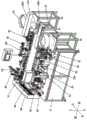
FIG. 1 is a first perspective view of an embodiment of the present invention;
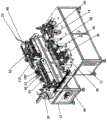
FIG. 2 is a second perspective view of the embodiment of the present invention;
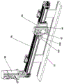
FIG. 3 is a schematic view of a first grasping mechanism according to an embodiment of the present invention;
FIG. 4 is a schematic view of a first feed mechanism of an embodiment of the present invention;
FIG. 5 is a schematic view of a thread trimming mechanism according to an embodiment of the present invention;
FIG. 6 is a schematic view of a rotary mechanism according to an embodiment of the present invention;
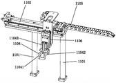
FIG. 7 is a schematic view of a second gripper mechanism according to an embodiment of the invention;
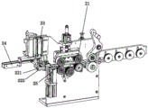
fig. 8 is a schematic view of a second feeding mechanism and a welding mechanism according to an embodiment of the present invention.
The attached drawings indicate the following:
11. left body 12, right body
13. Positioning jig 131 and placing groove
132. Briquetting 14, straightening device
15. First cover body
20. First feeding mechanism 21 and conveying wheel set
221. First clamping head 222 and second clamping head
23. First and second driving devices 24 and 24
25. First cutting device 30 and first peeling mechanism
40. Wire arrangement mechanism 41 and first base
421. Upper press holding part 422 and lower press holding part
423. Fifth drive device 431 and upper positioning head
432. Lower positioning head 433 and sixth driving device
44. First displacement device 45 and auxiliary thread trimming mechanism
50. Conveying mechanism 51 and first conveying device
52. Second conveying device 53 and positioning plate
531. Positioning groove 532, guide slope
60. Second peeling mechanism 70 and second feeding mechanism
71. Second base 72, welding seat
721. Feeding channel 722 and feeding hole
723. Discharge port 73 and feeding pipeline
74. Push rod 741 and eighth driving device
75. Seventh driving device 80 and welding mechanism
81. Welding head 90 and first grabbing mechanism
91. Mounting seat 92 and first movable seat
93. First grabbing head 931 and first clamping head
932. Second gripping head 94, third driving device
95. First slide rail 96 and fourth driving device
97. First grabbing driving device 98 and second cover body
100. Rotating mechanism
1001. Upper rotary clamping head 1002 and lower rotary clamping head
1003. First clamping device 1004 and rotating device
110. Second grasping mechanism 1101, fixing lever
1102. Second slide rail 1103 and second movable seat
1104. A second gripper head 11041 and a third gripper portion
11042. Fourth gripper 11043, second gripper driving device
11044. Grabbing end 1105 and first displacement driving device
1106. Second displacement driving device 120 and material receiving module
121. And a third grabbing mechanism.
Detailed Description
Referring to fig. 1 to 8, specific structures of the embodiments of the present invention are shown.
A full-automatic double-head peeling and welding machine for data wires comprises a left machine body 11, a right machine body 12, a first feeding mechanism 20 for conveying and cutting the data wires, a first peeling mechanism 30 for peeling the outer cover of the data wires, a wire straightening mechanism 40 for flattening and adjusting the relative positions of two core wires, a positioning clamp 13 for clamping and positioning the data wires, a conveying mechanism 50 for conveying the displacement of the positioning clamp, a second peeling mechanism 60 for peeling the outer cover of the core wires, a second feeding mechanism 70 for conveying joints and a welding mechanism 80 for welding the joints and the core wires; wherein: the first peeling mechanism 30, the wire arranging mechanism 40, the positioning fixture 13, the conveying mechanism 50, the second peeling mechanism 60, the second feeding mechanism 70 and the welding mechanism 80 are respectively arranged on the left machine body 11 and the right machine body 12 and are symmetrically arranged, the first feeding mechanism 20 is arranged on any one machine body, a first grabbing mechanism 90 for grabbing and transferring one end of a data wire to the corresponding machine body is arranged between the left machine body 11 and the right machine body 12, and the first grabbing mechanism 90 is positioned beside the first feeding mechanism 20; the conveying mechanism 50 comprises a first conveying device 51 and a second conveying device 52 which are arranged in a front-back spacing manner, the first conveying device 51 is positioned between the first grabbing mechanism 90 and the first feeding mechanism 20, the positioning clamps 13 are respectively arranged on the first conveying device 51 and the second conveying device 52, the first peeling mechanism 30 and the wire arranging mechanism 40 are arranged in a spacing manner along the conveying direction of the first conveying device 51, the second peeling mechanism 60, the second feeding mechanism 70 and the welding mechanism 80 are arranged in a spacing manner along the conveying direction of the second conveying device 52, and a second grabbing mechanism 110 for transferring the data wire of the first conveying device 51 to the second conveying device 52 is arranged between the first conveying device 51 and the second conveying device 52; preferably, the first conveying device 51 and the second conveying device 52 are both chain conveying devices, and the left body 11 and the right body 12 are both provided with first covers 15, and the first covers 15 are arranged on opposite sides between the left body 11 and the right body 12 corresponding to the conveying mechanism 50; therefore, through the design of each mechanism, the automatic production of the data line and the joint is realized, the production efficiency of the data line is improved, the processing quality is stable and consistent, and the production cost of the data line is reduced.
As shown in fig. 1, fig. 2, and fig. 4, in this embodiment, the first feeding mechanism 20 is disposed on the right body 12, the first feeding mechanism 20 includes a conveying wheel set 21 for conveying a data line, a clamping assembly for clamping and positioning the data line, a first driving device 23 for controlling the clamping assembly to move up and down, a second driving device 24 for controlling the clamping assembly to move left and right, and a first cutting device 25 for cutting the data line, the first cutting device 25 is located between the clamping assembly and the conveying wheel set 21, and the clamping assembly is located above the first conveying device 50.
As shown in fig. 3, the first grabbing mechanism 90 includes a mounting base 91, a first moving base 92 and a first grabbing head, two ends of the mounting base 91 are fixed on the left body 11 and the right body 12, a first slide rail 95 extending left and right is disposed at an upper end of the mounting base 91, the first moving base 92 is disposed on the first slide rail 95 and movably disposed, the first moving base 92 is connected with a third driving device 94, the first moving base 92 reciprocates left and right on the first slide rail 95 under the control of the third driving device 94, the first grabbing head is disposed on the first moving base 92, the first grabbing head is provided with a slider, the slider is disposed on the first moving base 92 in a vertically movable manner, the slider is connected with a fourth driving device 96 for driving the slider to displace, and the first grabbing head is located at the left side of the clamping assembly; preferably, a second cover 98 is arranged on the mounting seat 91, the second cover 98 is arranged at the upper end of the mounting seat 91 and forms a mounting area with an open rear end with the mounting seat 91, the first moving seat 92, the first sliding rail 95, the third driving device 94 and the fourth driving device 96 are all arranged in the mounting area, and the first grabbing head is exposed outside the mounting area; when the data line clamping device is used, the data line sequentially passes through the first cutting device 25 and the clamping component along with the control of the conveying wheel set 21 and is exposed on the left side of the clamping component, the first grabbing head grabs the data line, the third driving device 94 drives the first moving seat 92 to move to the position above the positioning jig 13 of the first conveying device 51 of the left machine body 11, the conveying wheel set 21 and the third driving device 94 stop running, the clamping component clamps the data line, the first cutting device 25 cuts the data line, the first driving device 23 and the fourth driving device 96 run synchronously, so that the two ends of the data line are placed on the positioning jig 13 along with the control of the clamping component and the first grabbing head, and then the first driving device 23 and the fourth driving device 96 run synchronously and control the clamping component and the first grabbing head to reset respectively.
Here, the clamping assembly includes a first clamping head 221, a second clamping head 222, and a first clamping driving device for controlling the first clamping head 221 and the second clamping head 222 to perform clamping operation; the first gripper head comprises a first gripper portion 931, a second gripper portion 932 and a first gripper driving device 97 for controlling the first gripper portion 931 and the second gripper portion 932 to perform gripping; in addition, be provided with the standing groove 131 that is used for placing the data line on the positioning jig 13, be provided with the briquetting 132 on the standing groove 131, briquetting 132 movable formula sets up on positioning jig 13, and during the use, the data line is placed in the standing groove, and the briquetting moves towards the data line so that the briquetting pressure is held on the data line.
As shown in fig. 5, the wire straightening mechanism 40 includes a first base 41, and a pressing component and a wire spreading component which are disposed on the first base 41, the pressing component includes an upper pressing portion 421, a lower pressing portion 422, and a fifth driving device 423 for controlling the upper pressing portion 421 and the lower pressing portion 422 to perform a pressing operation, the upper pressing portion 421 and the lower pressing portion 422 are disposed at a middle position of the first base 41 and are located beside the first conveying device 51, the fifth driving device 423 is connected to a first displacement device 44 for controlling the upper pressing portion 421 and the lower pressing portion 422 to perform a left-right displacement operation, so that the upper pressing portion 421 and the lower pressing portion 422 perform a straightening operation after the core wire pressing operation; exhibition line subassembly is provided with two and sets up respectively in the preceding, the rear side of pressing and holding the subassembly, exhibition line subassembly is including last positioning head 431, lower positioning head 432 and control go up positioning head 431, lower positioning head 432 and fix a position the sixth drive arrangement 433 of operation with the expansion to the heart yearn to make two heart yearns expand and be the splayed.
Preferably, an auxiliary wire straightening mechanism 45 for positioning and straightening the unfolded core wires is arranged at the rear side of the wire straightening mechanism 40, the auxiliary wire straightening mechanism comprises an upper auxiliary pressing part, a lower auxiliary pressing part, a first auxiliary driving device for controlling the upper auxiliary pressing part and the lower auxiliary pressing part to perform the up-and-down pressing action, and a second auxiliary driving device for controlling the first auxiliary driving device to perform the left-and-right reciprocating displacement, first grooves matched with the two core wires are respectively arranged at the opposite sides of the upper auxiliary pressing part and the lower auxiliary pressing part, and the upper auxiliary pressing part and the lower auxiliary pressing part are vertically pressed together along with the control of the first auxiliary driving device so that the two core wires are limited in the grooves and are straightened by the control of the second auxiliary driving device.
The first conveying device 51 is provided with a first positioning assembly and a second positioning assembly corresponding to the wire arranging mechanism 40 and the auxiliary wire arranging mechanism 45 respectively, the first positioning assembly comprises a first positioning part, a first positioning plate and a first positioning driving device for driving the first positioning plate to move, the first positioning part is provided with a first yielding port, the lower end of the first positioning plate is provided with a second groove, the data wire moves to the upper end of the first positioning part, the first positioning driving device controls the first positioning plate to move downwards and extend into the first yielding port, and the periphery of the data wire is limited in the second groove so as to realize the positioning of the data wire; the second positioning assembly comprises a second positioning part, a second positioning plate and a second positioning driving device for driving the second positioning plate to move, a third groove is formed in the second positioning part, the lower end of the second positioning plate is arranged in an arrow shape, the expanded core wire is moved to the upper end of the second positioning part, the second positioning driving device controls the second positioning plate to move towards the third groove, so that the inner side between the two core wires is limited by the two sides of the lower end of the second positioning plate, and the expanded core wire is positioned and straightened by the aid of the auxiliary wire straightening mechanism.
The device is further provided with an identification module for identifying whether the positions of the two core wires are correct or not and a rotating mechanism 100 for rotating the two core wires, wherein the rotating mechanism 100 comprises an upper rotating and clamping head 1001, a lower rotating and clamping head 1002, a first clamping device 1003 for controlling the upper rotating and clamping head 1001 and the lower rotating and clamping head 1002 to perform clamping actions and a rotating device 1004 for controlling the first clamping device 1003 to rotate, and the identification module is arranged on one side of the rotating mechanism; when the device is used, the identification module identifies two core wires, when the positions of the two core wires are not aligned, the identification module feeds information back to the rotating mechanism 100, the rotating mechanism 100 clamps the data wire by using the upper rotating clamping head 1001 and the lower rotating clamping head 1002, and then the rotating device 1004 rotates the two core wires so as to exchange the positions of the two core wires.
As shown in fig. 8, the second conveying device 52 is provided with a positioning plate 53 for positioning two core wires, the positioning plate 53 is provided with two positioning grooves 531 arranged at intervals, and the two core wires are respectively positioned in the two corresponding positioning grooves 531; here, the upper end of the positioning groove 531 is provided with a guide slope 532.
The straightening device is characterized in that a straightening device 14 used for straightening two core wires is further arranged, the straightening device is arranged beside the side of the second conveying device 52 and located on the front side of the second peeling mechanism 60, the straightening device comprises a third clamping head, a fourth clamping head, a second clamping driving device used for controlling the third clamping head and the fourth clamping head to perform pressing operation and a straightening driving device used for controlling the second clamping driving device to perform left-right reciprocating displacement, two fourth grooves matched with the two core wires are arranged on the opposite sides of the third clamping head and the fourth clamping head, and the two core wires are respectively limited in the corresponding fourth grooves and are straightened by the straightening driving device.
The second peeling mechanism 60 includes a second cutting device for cutting the core wire and a peeling device for peeling the core wire, and the second cutting device is located between the straightening device 14 and the peeling device, so that the core wire is peeled after being cut to a required length.
The second feeding mechanism 70 comprises a second base 71, a welding seat 72, a feeding pipeline 73 and a push rod 74, wherein the welding seat 72 is movably arranged on the second base 71 through a seventh driving device 75, a feeding channel 721 is arranged in the welding seat 72, a feeding port 722 and a discharging port 723 are arranged on the welding seat 72, the feeding pipeline 73 is communicated with the feeding port 722 of the welding seat 72, the discharging port 723 is arranged towards the second conveying device 52, one end of the push rod 74 extends into the feeding channel 721, and the other end of the push rod 74 is connected with an eighth driving device 741; the welding mechanism 80 comprises a welding head 81 and a ninth driving device for controlling the welding head to move up and down, and the welding head 81 is positioned above the welding seat 72; when the welding device is used, the core wires are moved to the position of the second feeding mechanism 70 through the second conveying device 52, the joint of the feeding pipeline 73 enters the feeding channel 721 through the feeding hole 722, the push rod 74 pushes the joint to the discharging hole 723 along with the control of the eighth driving device 741, the welding position of the joint is exposed out of the discharging hole 723, the seventh driving device controls the welding seat 75 to move to the position of two core wires, the two core wires are respectively abutted to the welding positions corresponding to the joints, and the welding head 81 is controlled by the ninth driving device to move downwards so that the welding head 81 performs welding operation on the core wires and the joint.
And the second grabbing mechanism 110 comprises a fixing rod 1101, a second sliding rail 1102, a second moving seat 1103 and a second grabbing head 1104, the fixing rods 1101 are provided in two and arranged in a front-to-back spaced manner between the first and second conveyors 51 and 52, the second slide rail 1102 extends back and forth, two ends of the second slide rail 1102 are respectively fixed on the two fixing rods 1101, the second moving seat 1103 is movably disposed on the second sliding rail 1102, the second moving seat 1103 is connected to a first displacement driving device 1105, the second gripper head 1104 is disposed on the second movable base 1103, a second displacement driving device 1106 for driving the second gripper head 1104 to displace up and down is disposed on the second movable base 1103, the second gripper head 1104 includes a third gripper portion 11041, a fourth gripper portion 11042, and a second gripper driving device 11043 for controlling the third gripper portion and the fourth gripper portion to perform the gripping operation; preferably, the third grabbing portion 11041 and the fourth grabbing portion 11042 are provided with two grabbing ends arranged in a left-right spacing manner, an avoiding region is formed between the two grabbing ends, when the device is used, the second grabbing head 1104 moves to the positioning jig 13, the two grabbing ends of the third grabbing portion 11041 and the two grabbing ends of the fourth grabbing portion 11042 are respectively located on the left side and the right side of the positioning jig 13, and the second grabbing driving device 11043 controls the grabbing ends to grab and move the data lines.
The material collecting module 120 is used for capturing and storing the welded data lines, and the material collecting module 120 comprises two third capturing mechanisms 1201, wherein the two third capturing mechanisms 1201 are respectively arranged on the left machine body 11 and the right machine body 12 and are positioned at the rear sides of the corresponding welding mechanisms 80.
The design of the invention is characterized in that the data wire is conveyed, grabbed and cut by utilizing the first feeding mechanism and the first grabbing mechanism through the design of each mechanism, the two ends of the data wire are respectively limited on the positioning jigs of the corresponding machine bodies, and the data wire is moved to each procedure for processing by utilizing the conveying mechanism, so that the automatic production of the data wire and the joint is realized, the production efficiency of the data wire is improved, the processing quality is stable and consistent, the structural design is ingenious and reasonable, the operation is simple, the use is convenient, the processing time is short, and the production cost of the data wire is reduced; secondly, the arrangement of the wire arrangement mechanism enables the core wires to be flattened and straightened, and then two core wires are unfolded and positioned, so that the subsequent welding positioning of the core wires and the joints is facilitated, the production efficiency of the data wire is effectively improved, meanwhile, the arrangement of the wire arrangement mechanism is assisted, the stability of the core wires after being unfolded is facilitated, and the arrangement of the identification module and the rotating mechanism avoids the phenomenon that the positions of the core wires and the joints are incorrect in the subsequent welding process, so that the data wire cannot be used, the correct positions of the core wires are ensured, and the stable and consistent processing quality of the data wire is ensured; moreover, the positioning plate and the positioning groove are arranged, so that the expanded core wire is positioned when being moved to the positioning jig of the second conveying device, the phenomenon that the subsequently expanded core wire deviates in the moving process of the positioning jig is avoided, the subsequent core wire and the joint are correctly welded, and meanwhile, the arrangement of the straightening device is favorable for the stable positioning of the core wire on the positioning groove, so that the subsequent working procedure can be conveniently processed; and the welding seat, the feeding pipeline and the push rod are arranged, so that automatic feeding of the joint is realized, and the joint and the core wire are positioned and welded, so that automatic production of the data wire is realized, the automation degree is high, and the application range is wide.
The above description is only a preferred embodiment of the present invention, and is not intended to limit the technical scope of the present invention, so that any minor modifications, equivalent changes and modifications made to the above embodiment according to the technical spirit of the present invention are within the technical scope of the present invention.
Claims (10)
1. The utility model provides a full-automatic double-end welding machine of skinning of data line which characterized in that: the device comprises a left machine body, a right machine body, a first feeding mechanism for conveying and cutting a data line, a first peeling mechanism for peeling a quilt from the data line, a line straightening mechanism for flattening and adjusting the relative positions of two core lines, a positioning clamp for clamping and positioning the data line, a conveying mechanism for conveying the displacement of the positioning clamp, a second peeling mechanism for peeling the quilt from the core lines, a second feeding mechanism for conveying a joint and a welding mechanism for welding the joint and the core lines; wherein: the first peeling mechanism, the wire arranging mechanism, the positioning fixture, the conveying mechanism, the second peeling mechanism, the second feeding mechanism and the welding mechanism are respectively arranged on the left machine body and the right machine body and are symmetrically arranged, the first feeding mechanism is arranged on any one machine body, a first grabbing mechanism used for grabbing and transferring one end of a data wire to the corresponding machine body is arranged between the left machine body and the right machine body, and the first grabbing mechanism is positioned beside the first feeding mechanism; the conveying mechanism comprises a first conveying device and a second conveying device which are arranged at intervals front and back, the first conveying device is located between a first grabbing mechanism and a first feeding mechanism, the positioning clamps are respectively arranged on the first conveying device and the second conveying device, the first peeling mechanism and the line arranging mechanism are arranged at intervals along the conveying direction of the first conveying device, the second peeling mechanism, the second feeding mechanism and the welding mechanism are arranged at intervals along the conveying direction of the second conveying device, and a second grabbing mechanism used for transferring the data line of the first conveying device to the second conveying device is arranged between the first conveying device and the second conveying device.
2. The full-automatic double-end of data line welding machine of skinning of claim 1 characterized in that: first feeding mechanism sets up on right organism, first feeding mechanism is including the conveying wheelset that is used for carrying the data line, the centre gripping subassembly that is used for centre gripping location data line, the first drive arrangement who is used for controlling centre gripping subassembly displacement from top to bottom, the second drive arrangement who is used for controlling centre gripping subassembly and controls the displacement and the first cutting device who is used for cutting the data line, first cutting device is located between centre gripping subassembly, the conveying wheelset, the centre gripping subassembly is located first conveyor's top.
3. The full-automatic double-end of data line welding machine of skinning of claim 2 characterized in that: first mechanism of snatching is including mount pad, first removal seat and the first head of snatching, the both ends of mount pad are fixed in on left organism, the right organism, the upper end of mount pad is provided with the first slide rail of extending about, first removal seat sets up on first slide rail and movable setting, first removal seat is connected with third drive arrangement, first removal seat is along with third drive arrangement's control on first slide rail reciprocating displacement about, first head of snatching sets up on first removal seat, first overhead slider that is provided with of snatching, slider movable from top to bottom sets up on first removal seat, the slider is connected with the fourth drive arrangement who is used for driving the slider displacement, first head of snatching is located the left side of centre gripping subassembly.
4. The full-automatic double-end of data line welding machine of skinning of claim 1 characterized in that: the wire straightening mechanism comprises a first base, a pressing and holding assembly and a wire spreading assembly, wherein the pressing and holding assembly is arranged on the first base and comprises an upper pressing and holding part, a lower pressing and holding part and a fifth driving device for controlling the upper pressing and holding part and the lower pressing and holding part to perform pressing actions; the wire unfolding component is provided with two wires which are respectively arranged at the front side and the rear side of the pressing component, and comprises an upper positioning head, a lower positioning head and a sixth driving device for controlling the upper positioning head and the lower positioning head to position and unfold the core wires, so that the two core wires are unfolded to be splayed.
5. The full-automatic double-end peeling and welding machine of data line of claim 4, characterized in that: and an auxiliary wire straightening mechanism for positioning and straightening the unfolded core wire is arranged at the rear side of the wire straightening mechanism.
6. The full-automatic double-end peeling and welding machine for data lines according to claim 5, is characterized in that: the core wire clamping device is characterized by further comprising an identification module and a rotating mechanism, wherein the identification module is used for identifying whether the positions of the two core wires are correct, the rotating mechanism is used for rotating the two core wires, the rotating mechanism comprises an upper rotating clamping head, a lower rotating clamping head, a first clamping device and a rotating device, the first clamping device is used for controlling the upper rotating clamping head and the lower rotating clamping head to perform clamping actions, the rotating device is used for controlling the first clamping device to rotate, and the identification module is arranged on one side of the rotating mechanism.
7. The full-automatic double-end of data line welding machine of skinning of claim 1 characterized in that: the second conveying device is provided with a positioning plate for positioning two core wires, the positioning plate is provided with two positioning grooves which are arranged at intervals, and the two core wires are positioned in the two corresponding positioning grooves respectively.
8. The full-automatic double-end of data line welding machine of skinning of claim 1 characterized in that: and the straightening device is used for straightening the two core wires and is arranged beside the second conveying device and positioned at the front side of the second peeling mechanism.
9. The full-automatic double-end of data line welding machine of skinning of claim 8 characterized in that: the second peeling mechanism comprises a second cutting device for cutting the core wire and a peeling device for peeling the core wire, and the second cutting device is located between the straightening device and the peeling device so that the core wire is peeled after being cut to the required length.
10. The full-automatic double-end of data line welding machine of skinning of claim 1 characterized in that: the second feeding mechanism comprises a second base, a welding seat, a feeding pipeline and a push rod, the welding seat is movably arranged on the second base through a seventh driving device, a feeding channel is arranged in the welding seat, a feeding hole and a discharging hole are formed in the welding seat, the feeding pipeline is communicated with the feeding hole of the welding seat, the discharging hole is arranged towards the second conveying device, one end of the push rod extends into the feeding channel, and the other end of the push rod is connected with an eighth driving device; and the welding mechanism comprises a welding head and a ninth driving device for controlling the welding head to move up and down, and the welding head is positioned above the welding seat.
Priority Applications (1)
| Application Number | Priority Date | Filing Date | Title |
|---|---|---|---|
| CN202111005444.0A CN113783074B (en) | 2021-08-30 | 2021-08-30 | Full-automatic double-end peeling welding machine for data lines |
Applications Claiming Priority (1)
| Application Number | Priority Date | Filing Date | Title |
|---|---|---|---|
| CN202111005444.0A CN113783074B (en) | 2021-08-30 | 2021-08-30 | Full-automatic double-end peeling welding machine for data lines |
Publications (2)
| Publication Number | Publication Date |
|---|---|
| CN113783074A true CN113783074A (en) | 2021-12-10 |
| CN113783074B CN113783074B (en) | 2023-12-26 |
Family
ID=78840172
Family Applications (1)
| Application Number | Title | Priority Date | Filing Date |
|---|---|---|---|
| CN202111005444.0A Active CN113783074B (en) | 2021-08-30 | 2021-08-30 | Full-automatic double-end peeling welding machine for data lines |
Country Status (1)
| Country | Link |
|---|---|
| CN (1) | CN113783074B (en) |
Cited By (2)
| Publication number | Priority date | Publication date | Assignee | Title |
|---|---|---|---|---|
| CN114498238A (en) * | 2022-02-26 | 2022-05-13 | 无锡市鸿翔电子有限公司 | Data line welding process and welding device |
| CN114709700A (en) * | 2022-04-26 | 2022-07-05 | 武汉浅小黑百货有限公司 | Data line production and processing system and production and processing technology |
Citations (4)
| Publication number | Priority date | Publication date | Assignee | Title |
|---|---|---|---|---|
| US8011557B1 (en) * | 2010-08-04 | 2011-09-06 | Cheng Uei Precision Industry Co., Ltd. | Automatic soldering machine |
| CN102637988A (en) * | 2012-04-05 | 2012-08-15 | 东莞市三信精密机械有限公司 | Automatic cable and connector processing, welding and assembling machine |
| CN102931565A (en) * | 2012-10-19 | 2013-02-13 | 东莞市三信精密机械有限公司 | Fully-automatic cable processing equipment |
| CN216750630U (en) * | 2021-08-30 | 2022-06-14 | 深圳市帆与航电子科技有限公司 | Full-automatic double-end welding machine of skinning of data line |
-
2021
- 2021-08-30 CN CN202111005444.0A patent/CN113783074B/en active Active
Patent Citations (4)
| Publication number | Priority date | Publication date | Assignee | Title |
|---|---|---|---|---|
| US8011557B1 (en) * | 2010-08-04 | 2011-09-06 | Cheng Uei Precision Industry Co., Ltd. | Automatic soldering machine |
| CN102637988A (en) * | 2012-04-05 | 2012-08-15 | 东莞市三信精密机械有限公司 | Automatic cable and connector processing, welding and assembling machine |
| CN102931565A (en) * | 2012-10-19 | 2013-02-13 | 东莞市三信精密机械有限公司 | Fully-automatic cable processing equipment |
| CN216750630U (en) * | 2021-08-30 | 2022-06-14 | 深圳市帆与航电子科技有限公司 | Full-automatic double-end welding machine of skinning of data line |
Cited By (4)
| Publication number | Priority date | Publication date | Assignee | Title |
|---|---|---|---|---|
| CN114498238A (en) * | 2022-02-26 | 2022-05-13 | 无锡市鸿翔电子有限公司 | Data line welding process and welding device |
| CN114498238B (en) * | 2022-02-26 | 2022-12-13 | 无锡市鸿翔电子有限公司 | Data line welding process and welding device |
| CN114709700A (en) * | 2022-04-26 | 2022-07-05 | 武汉浅小黑百货有限公司 | Data line production and processing system and production and processing technology |
| CN114709700B (en) * | 2022-04-26 | 2023-10-13 | 东莞市鑫赣辉电子科技有限公司 | Data line production and processing system and production and processing technology |
Also Published As
| Publication number | Publication date |
|---|---|
| CN113783074B (en) | 2023-12-26 |
Similar Documents
| Publication | Publication Date | Title |
|---|---|---|
| CN104028904B (en) | Bimetal element automatic welding machine | |
| CN109994908A (en) | A kind of automatic bonding equipment of DC charging terminal | |
| CN113783074A (en) | Full-automatic double-end welding machine of skinning of data line | |
| CN110718829B (en) | Production line of electron pencil | |
| CN107394275B (en) | Battery cell transfer piece welding machine | |
| CN112621148B (en) | Automatic assembly process for automobile parts | |
| CN111531238A (en) | Transformer welding and assembling integrated production line | |
| CN216750630U (en) | Full-automatic double-end welding machine of skinning of data line | |
| CN112186455A (en) | Circuit board lead welding equipment and welding method | |
| CN110744825A (en) | Pin inserting device for plastic parts | |
| CN209896414U (en) | Automatic wire welding machine for DC charging terminal | |
| CN218549041U (en) | Automatic wire welding machine | |
| CN110112871B (en) | Automatic production line of motor stator | |
| CN208571200U (en) | A kind of full-automatic single-head wears protective pipe sleeve terminal machine | |
| CN106514353A (en) | Shifting and clamping tool for pipe bend | |
| CN218069643U (en) | Multi-lead capacitor welding assembly machine | |
| CN215645400U (en) | Branching and twisting device for double-core wire | |
| CN210041596U (en) | Winding device of motor stator | |
| CN217545208U (en) | Stable welding machine of skinning is transferred to wire rod | |
| CN112218445A (en) | Wire bending device of circuit board welding machine | |
| CN216055655U (en) | Full-automatic double-end processing equipment of data line | |
| CN214444003U (en) | Automatic spot welding machine | |
| CN216706234U (en) | Accurate material feeding unit and system of full-automatic soldering of connector | |
| CN211194978U (en) | Pin inserting device for plastic parts | |
| CN216528752U (en) | Cutting device and battery string production equipment |
Legal Events
| Date | Code | Title | Description |
|---|---|---|---|
| PB01 | Publication | ||
| PB01 | Publication | ||
| SE01 | Entry into force of request for substantive examination | ||
| SE01 | Entry into force of request for substantive examination | ||
| GR01 | Patent grant | ||
| GR01 | Patent grant |