Disclosure of Invention
The technical problem to be solved by the invention is as follows: before the manipulator picks, the anti-side-rolling torsion bar shaft needs to be manually put on the corresponding position of the material frame one by one, so that the problems of high labor intensity and low working efficiency are caused.
Aiming at the problems, the technical scheme provided by the invention is as follows:
an automatic feeding device in a torsion bar shaft upsetting process flow comprises a main frame and a distribution mechanism; the front part and the rear part of the main frame are respectively provided with a material taking frame and a material stacking frame, the distribution mechanism is arranged on the main frame between the material taking frame and the material stacking frame, the torsion bar shafts on the material stacking frame can be distributed to the material taking frame, and only one torsion bar shaft is distributed to the material taking frame each time; the material taking frame is provided with only one torsion bar shaft to be grabbed.
Further, a material preparing frame is arranged on the main frame between the material taking frame and the material stacking frame.
Furthermore, the stacking frame comprises a left placing beam I and a right placing beam I which are arranged in a bilateral symmetry mode, the left placing beam I and the right placing beam I are arranged in a forward and downward inclined mode, and a left blocking column I and a right blocking column I are arranged at the front ends of the left placing beam I and the right placing beam I in a vertical and upward symmetry mode.
The material preparation frame comprises a left placing beam II and a right placing beam II which are arranged in a bilateral symmetry manner, the left placing beam II and the right placing beam II are arranged forwards and downwards in a downward inclined manner, a left blocking column II and a right blocking column II are vertically and upwards symmetrically arranged at the front ends of the left placing beam II and the right placing beam II, the rear ends of the left placing beam II and the right placing beam II are respectively fixedly connected with the upper ends of the left blocking column I and the right blocking column I, and the upper surfaces of the left placing beam II and the right placing beam II are respectively arranged on an inclined surface with the upper end surfaces of the left blocking column I and the right blocking column I;
a plurality of torsion bar shafts can be placed on the material preparing frame, and two ends of the plurality of torsion bar shafts are placed on the left placing beam II and the right placing beam II respectively.
Furthermore, the material taking frame comprises a left placing beam III and a right placing beam III which are arranged in a bilateral symmetry manner, the left placing beam III and the right placing beam III are arranged in a forward and downward inclined manner, a left blocking column III and a right blocking column III are symmetrically arranged at the front ends of the left placing beam III and the right placing beam III in a vertical and upward manner, the rear ends of the left placing beam III and the right placing beam III are fixedly connected with the upper ends of the left blocking column II and the right blocking column II respectively, and the upper surfaces of the left placing beam III and the right placing beam III are respectively arranged on an inclined plane together with the upper end surfaces of the left blocking column II and the right blocking column II.
Further, the distributing mechanism comprises a primary distributing mechanism positioned below the front end of the stacking frame;
the primary distributing mechanism comprises a primary left jacking component and a primary right jacking component which are arranged below the front end of the stacking frame in a bilateral symmetry manner; the primary left jacking component comprises a primary left lifter with a lifting piece and a primary left supporting block fixed on the lifting piece, and the primary right jacking component comprises a primary right lifter with a lifting piece and a primary right supporting block fixed on the lifting piece; the top surfaces of the first-stage left supporting block and the first-stage right supporting block are inclined forwards and downwards; the first-stage left supporting block and the first-stage right supporting block can ascend and descend along with respective lifting pieces; the first-level left supporting block and the first-level right supporting block synchronously ascend and can jack up at least one torsion bar shaft.
Further, the distributing mechanism also comprises a secondary distributing mechanism positioned below the front end of the material preparing frame;
the secondary distributing mechanism comprises a secondary left jacking component and a secondary right jacking component which are arranged below the front end of the stacking frame in a bilateral symmetry manner; the second-stage left jacking assembly comprises a second-stage left lifter with a lifting piece and a second-stage left supporting block fixed on the lifting piece, and the second-stage right jacking assembly comprises a second-stage right lifter with a lifting piece and a second-stage right supporting block fixed on the lifting piece; the top surfaces of the secondary left supporting block and the secondary right supporting block are inclined forwards and downwards; the secondary left supporting block and the secondary right supporting block can ascend and descend along with respective lifting pieces; the second-stage left supporting block and the second-stage right supporting block can synchronously ascend and only jack up one torsion bar shaft.
Furthermore, a first-stage left lifter and a first-stage right lifter of the first-stage distributing mechanism are both electric lifters, and a first hair loosening type power switch is shared; the first loosening type power switch is arranged on one side of the second left rest beam or one side of the second right rest beam and can be pressed to be closed by any one torsion bar shaft; when the pressure of the torsion bar shaft is lost when the hair loosening type power switch, the primary left lifter and the primary right lifter can be synchronously started, and the primary left supporting block and the primary right supporting block are synchronously pushed to finish one ascending-pausing-descending action.
Furthermore, the first loose power switch is provided with a first press arm for controlling the power switch; the rear end of the first pressure arm is arranged on one side of the second left rest beam or one side of the second right rest beam through a rotating shaft, the rear end of the first pressure arm is lower than the upper surfaces of the second left rest beam and/or the second right rest beam, the front end of the first pressure arm can automatically bounce upwards to a height higher than the height of the second left rest beam and/or the height of the second right rest beam, and the front part of the first pressure arm can be pressed down by a torsion bar shaft rolling forwards on the second left rest beam and the second right rest beam; the first pressing arm can be pressed by two adjacent torsion bar shafts at least at the same time.
Furthermore, a secondary left lifter and a secondary right lifter of the secondary distribution mechanism are both electric lifters, and a first hair loosening type power switch is shared; the first loose power switch is arranged on one side of the left joist III or one side of the right joist III, and can be pressed to a closed position by only one torsion bar shaft; when the loose type power switch loses the torsion bar shaft pressing, the secondary left lifter and the secondary right lifter can be synchronously started, and the secondary left supporting block and the secondary right supporting block are synchronously pushed to finish one-time ascending-pause-descending action.
A method for automatically feeding materials in a torsion bar shaft upsetting process flow is characterized in that a feeding device is arranged in a grabbing area of a manipulator, at least one stacking frame and one material taking frame are arranged on the feeding device, a distribution mechanism is arranged on the feeding device, a plurality of torsion bar shafts are stacked on the stacking frame during material taking, the torsion bar shafts are distributed to the material taking frame from the stacking frame by the distribution mechanism, only one torsion bar shaft is distributed to the material taking frame each time, and when one torsion bar shaft on the material taking frame is taken away, the torsion bar shafts are distributed to the material taking frame by the distribution mechanism.
The manipulator grabbing device is characterized in that a feeding device is arranged in a grabbing area of the manipulator, a feeding general frame is arranged in the grabbing area, the front portion of the general frame is arranged on one side convenient for the manipulator to grab, a material taking frame is arranged on the front portion of the general frame, and a material stacking frame is arranged on the rear portion of the general frame.
And adding an equipment rack on a main rack between the material taking rack and the material stacking rack, wherein only one torsion bar shaft is distributed to the material taking rack each time, more than one torsion bar shaft is distributed to the material preparing rack from the torsion bar shafts stacked on the material stacking rack by a distribution mechanism at one time, and then one torsion bar shaft is distributed to the material taking rack from the material preparing rack each time.
Has the advantages that: under the condition that does not need the manual work to put, just can make convenient, quick, the accurate torsion bar axle that snatchs of manipulator, can not only avoid the human participation of high strength, also show and improve production efficiency.
Detailed Description
The invention is further described with reference to the following examples and figures:
example one
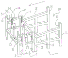
As shown in fig. 1-3, an automatic feeding device in the torsion bar shaft upsetting process is arranged in an area convenient for a manipulator to grab nearby, and comprises a general frame 100 and a distribution mechanism. The front part and the rear part of the general frame 100 are respectively provided with a material taking frame 3 and a material stacking frame 1. The stacker 1 is used for tens of torsion bar shafts 6 stacked in a basket or bundle at a time. The dispensing mechanism is arranged on the general frame 100 between the material taking frame 3 and the material stacking frame 1. Because the manipulator is thick, can't snatch one alone from the torsion bar shaft 6 that a plurality of pile up or arrange together, consequently need the distribution mechanism to distribute the torsion bar shaft on the stacker 1 to the work or material taking frame 3, and only distribute a torsion bar shaft 6 to the work or material taking frame 3 at every turn, deposit the torsion bar shaft 6 that a standby manipulator snatched on the work or material taking frame 3. There are various ways to dispense one torsion bar shaft 6 to the material taking rack 3, for example, the dispensing mechanism may take several torsion bar shafts 6 at a time from one stack of torsion bar shafts 6 of the material stacking rack 1, but only one torsion bar shaft 6 may be dispensed to the material taking rack 3, or one torsion bar shaft 6 may be dispensed directly to the material taking rack 3 at a time from one stack of torsion bar shafts 6 of the material stacking rack 1. Like this, under the condition that does not need the manual work to put, just can make convenient, quick, the accurate torsion bar axle 6 that snatchs of manipulator, can not only avoid the manpower of high strength to participate in, still show to improve production efficiency.
A stock shelf 2 is arranged on the general shelf 100 between the material taking shelf 3 and the material stacking shelf 1 and is used for firstly placing a small number of torsion bar shafts 6 which are taken out at a time from dozens of torsion bar shafts stacked on the material stacking shelf 1 so as to adopt further measures and then distribute one torsion bar shaft from the stock shelf 2 to the material taking shelf 3 at a time
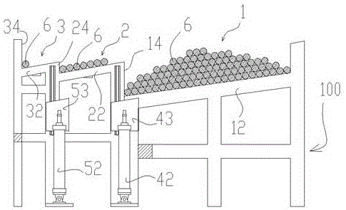
The stacking frame 1 comprises a left placing beam I11 and a right placing beam I12 which are arranged in a bilateral symmetry mode, the left placing beam I11 and the right placing beam I12 are arranged in a forward and downward inclined mode, a left retaining column I13 and a right retaining column I14 are symmetrically arranged at the front ends of the left placing beam I11 and the right placing beam I12 in a vertical and upward mode, and a left rear retaining column I15 and a right rear retaining column I16 are symmetrically arranged at the rear ends of the left placing beam I11 and the right placing beam I12 in a vertical and upward mode. Among dozens of torsion bar shafts 6 stacked on the stacking rack 1, two ends of a layer of torsion bar shafts 6 at the bottom are respectively placed on the left joist I11 and the right joist I12, and more torsion bar shafts 6 are stacked above the layer of torsion bar shafts 6 at the bottom due to the fact that the number of the torsion bar shafts 6 is large. Because the left joist I11 and the right joist I12 are inclined forwards and downwards, dozens of torsion bar shafts 6 stacked on the stacking rack 1 have a general forward rolling tendency under the action of gravity, but the general forward rolling tendency is blocked by the left blocking column I13 and the right blocking column I14.
The material preparing frame 2 comprises a left placing beam II 21 and a right placing beam II 22 which are arranged in a bilateral symmetry manner, the left placing beam II 21 and the right placing beam II 22 are arranged forwards and downwards in a downward inclination manner, the front ends of the left placing beam II 21 and the right placing beam II 22 are respectively and vertically and upwards provided with a left blocking column II 23 and a right blocking column II 24 in a symmetrical manner, the rear ends of the left placing beam II 21 and the right placing beam II 22 are respectively and fixedly connected with the upper ends of the left blocking column I13 and the right blocking column I14, and the upper surfaces of the left placing beam II 21 and the right placing beam II 22 are respectively and respectively arranged on an inclined surface with the upper end surfaces of the left blocking column I13 and the right blocking column I14;
a plurality of torsion bar shafts 6 (generally not more than 10) can be placed on the material preparing frame 2, and two ends of the placed torsion bar shafts 6 are respectively placed on the left shelf beam II 21 and the right shelf beam II 22. Because the left rest beam II 21 and the right rest beam II 22 are both inclined forwards and downwards, the plurality of torsion bar shafts 6 resting on the left rest beam II 21 and the right rest beam II 22 have a tendency of rolling forwards under the action of gravity, but the tendency is blocked by the left blocking column II 23 and the right blocking column II 24, so that a layer of discharge with adjacent torsion bar shafts 6 close together is formed on the left rest beam II 21 and the right rest beam II 22.
The material taking frame 3 comprises a left shelf beam III 31 and a right shelf beam III 32 which are arranged in a bilateral symmetry manner, the left shelf beam III 31 and the right shelf beam III 32 are arranged in a forward and downward inclined manner, a left blocking column III 33 and a right blocking column III 34 are arranged at the front ends of the left shelf beam III 31 and the right shelf beam III 32 in a vertical and upward symmetry manner, the rear ends of the left shelf beam III 31 and the right shelf beam III 32 are respectively fixedly connected with the upper ends of a left blocking column II 23 and a right blocking column II 24, and the upper surfaces of the left shelf beam III 31 and the right shelf beam III 32 are respectively arranged on an inclined surface with the upper end surfaces of the left blocking column II 23 and the right blocking column II 24. Because the distributing mechanism only distributes one torsion bar shaft 6 to the material taking frame 3 at each time, only one torsion bar shaft 6 can be stored on the material taking frame 3, and simultaneously, because the left shelf beam III 31 and the right shelf beam III 32 are both inclined forwards and downwards, the distributed torsion bar shaft 6 can automatically roll forwards under the action of gravity until being blocked by the left bumping post III 33 and the right bumping post III 34, and becomes the torsion bar shaft 6 to be grabbed.
The distributing mechanism comprises a primary distributing mechanism 4 positioned below the front end of the stacking frame 1;
the primary distributing mechanism 4 comprises a primary left jacking component and a primary right jacking component which are arranged below the front end of the stacking frame 1 in a bilateral symmetry manner; the primary left jacking component comprises a primary left lifter with a lifting piece and a primary left supporting block 41 fixed on the lifting piece, and the primary right jacking component comprises a primary right lifter 42 with a lifting piece and a primary right supporting block 43 fixed on the lifting piece; the top surfaces of the first-stage left supporting block 41 and the first-stage right supporting block 43 are both inclined forwards and downwards; the first-stage left supporting block 41 and the first-stage right supporting block 43 can ascend and descend along with respective lifting pieces; the synchronous ascending of the primary left supporting block 41 and the primary right supporting block 43 can jack up at least one torsion bar shaft 6.
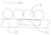
As shown in fig. 3-5, the primary left lifter and the primary right lifter 42 of the primary dispensing mechanism 4 are both electric lifters, and share a first loose power switch; the first loosening type power switch is arranged on one side of the second left rest beam 21 or one side of the second right rest beam 22 and can be pressed to a closed position by any one torsion bar shaft 6; when the pressure of the torsion bar shaft 6 is lost, the primary left lifter and the primary right lifter 42 can be synchronously started, and the primary left supporting block 41 and the primary right supporting block 43 are synchronously pushed to complete one ascending-pausing-descending action.
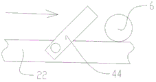
The hair-loosening power switch comprises a first pressure arm 44 for controlling the power switch; the rear end of the first pressure arm 44 is mounted on one side of the second left rest beam 21 or one side of the second right rest beam 22 through a rotating shaft, the rear end of the first pressure arm 44 is lower than the upper surfaces of the second left rest beam 21 and/or the second right rest beam 22, the front end of the first pressure arm 44 can automatically bounce upwards to a height higher than the height of the second left rest beam 21 and/or the second right rest beam 22, an acute angle is formed between the first pressure arm 44 and the upper surfaces of the second left rest beam 21 and/or the second right rest beam 22, and the front part of the first pressure arm 44 can be pressed down to be flush with the upper surfaces of the second left rest beam 21 and/or the second right rest beam 22 through the torsion rod shaft 6 rolling forwards on the second left rest beam 21 and the second right rest beam 22. When the first pressure arm 44 is pressed by the torsion bar shaft 6 and cannot be bounced, the pressing is performed, and when the first pressure arm 44 is pressed, the power supply of the first left lifter and the first right lifter 42 is disconnected; the first pressing arm 44 can be pressed by two adjacent torsion bar shafts 6 at least at the same time.
The primary distributing mechanism 4 has the working principle that the primary left lifter and the primary right lifter 42 synchronously push the primary left support block 41 and the primary right support block 43 to ascend, at least one or more (generally 3 to 5) torsion bar shafts 6 are jacked upwards at the front part of the material stacking frame 1, when the top surfaces of the primary left support block 41 and the primary right support block 43 rise to be flush with the top surfaces of the left baffle column I13 and the right baffle column I14, the torsion bar shafts 6 pause, the jacked torsion bar shafts 6 lose the blocking of the left baffle column I13 and the right baffle column I14, roll to the left placing beam II 21 and the right placing beam II 22 under the action of gravity, and then synchronously retract through the primary left lifter and the primary right lifter 42 to enable the primary left support block 41 and the primary right support block 43 to synchronously descend below the left placing beam I11 and the right placing beam I12, so that the action flow of the torsion bar shafts 6 from the material stacking frame 1 to the material preparing frame 2 is completed at one time.
As shown in fig. 4-5, when the torsion bar shafts 6 at the front of the stock shelf 2 are removed one by one and none of the torsion bar shafts 6 are pressed on the pressing arms 44 of the first release power switch, the pressing arms 44 are bounced, the circuit is closed, and the primary dispensing mechanism 4 starts a flow of dispensing the torsion bar shafts 6 from the stock shelf 1 to the stock shelf 2.
The first pressure arm 44 can be pressed by two adjacent torsion bar shafts 6 at least at the same time, that is, when the first pressure arm 44 is located at the front position of the stock rack 2, and it is to be ensured that when the previous torsion bar shaft 6 rolls away from the front end of the first pressure arm 44, the next adjacent pressure arm 44 should already press on the first pressure arm 44, so as to avoid the first pressure arm 44 bouncing up and starting the primary dispensing mechanism 4, because in the case that the stock rack 2 behind the first pressure arm 44 still contains the torsion bar shafts 6 to roll forward for replenishment, it is preferable not to start the primary dispensing mechanism 4 to replenish the stock rack 2 with the torsion bar shafts 6.
In principle, the further forward the pressure arm 44 is located on the stock preparation rack 2, the less frequent the primary dispensing mechanism 4 can be activated, as long as at least one torsion bar shaft 6 is ensured at the front end of the stock preparation rack 2. Therefore, the front end of the first pressing arm is preferably located at a position where the first torsion bar shaft 6 at the front end of the stock preparation rack 2 can press the front end of the first pressing arm.
As shown in fig. 1-3, the dispensing mechanism further includes a secondary dispensing mechanism 5 located below the front end of the stock frame 2;
the secondary distributing mechanism 5 comprises a secondary left jacking component and a secondary right jacking component which are arranged below the front end of the stacking frame 1 in a bilateral symmetry manner; the second-level left jacking component comprises a second-level left lifter with a lifting piece and a second-level left supporting block 51 fixed on the lifting piece, and the second-level right jacking component comprises a second-level right lifter 52 with a lifting piece and a second-level right supporting block 53 fixed on the lifting piece; the top surfaces of the secondary left supporting block 51 and the secondary right supporting block 53 are both inclined forwards and downwards; the secondary left supporting block 51 and the secondary right supporting block 53 can ascend and descend along with respective lifting pieces; the secondary left supporting block 51 and the secondary right supporting block 53 can synchronously ascend and only jack up one torsion bar shaft 6.
The second-stage left lifter and the second-stage right lifter 52 of the second-stage distributing mechanism 5 are both electric lifters and share a first hair loosening type power switch; the first loose power switch is arranged on one side of the third left joist 31 or one side of the third right joist 32 and can be pressed to a closed position by only one torsion bar shaft 6; when the pressure of the torsion bar shaft 6 is lost, the secondary left lifter and the secondary right lifter 52 can be synchronously started, and the secondary left supporting block 51 and the secondary right supporting block 53 are synchronously pushed to complete one ascending-pause-descending action.
The second pressure arm 54 of the first loose power switch with a control power switch; the rear end of the second pressure arm 54 is mounted on one side of the third left rest beam 31 or one side of the third right rest beam 32 through a rotating shaft, the rear end of the second pressure arm 54 is lower than the upper surfaces of the third left rest beam 31 and/or the third right rest beam 32, the front end of the second pressure arm 54 can automatically bounce upwards to a height higher than the height of the third left rest beam 31 and/or the third right rest beam 32, so that the second pressure arm 54 and the upper surfaces of the third left rest beam 31 and/or the third right rest beam 32 form an acute angle, and the front part of the second pressure arm 54 can be pressed down to be flush with the upper surfaces of the third left rest beam 31 and/or the third right rest beam 32 by the torsion rod shaft 6 rolling forwards on the third left rest beam 31 and the third right rest beam 32. The second pressing arm 54 is pressed by the torsion bar shaft 6, namely pressing is performed as described herein, and the power supply of the second-stage left lifter and the second-stage right lifter 52 is disconnected when the second pressing arm 54 is pressed; the second pressing arm 54 can be pressed by only one torsion bar shaft 6 on the material taking frame 3.
The working principle of the secondary distributing mechanism 5 is that the secondary left support block 51 and the secondary right support block 53 are synchronously pushed to ascend through the secondary left lifter and the secondary right lifter 52, the front part of the material preparing frame 2 is upwards jacked up and only one torsion bar shaft 6 can be jacked up, when the top surfaces of the secondary left support block 51 and the secondary right support block 53 ascend to be flush with the top surfaces of the left stop pillar II 23 and the right stop pillar II 24, the torsion bar shaft 6 is stopped, the jacked torsion bar shaft 6 loses the blocking of the left stop pillar II 23 and the right stop pillar II 24, the left shelf beam III 31 and the right shelf beam III 32 roll under the action of gravity, then the secondary left support block 51 and the secondary right support block 53 synchronously descend to be lower than the left shelf beam II 21 and the right shelf beam II 22 through the synchronous retraction of the secondary left lifter and the secondary right lifter 52, and the action flow of distributing one torsion bar shaft 6 from the material preparing frame 2 to the material taking frame 3 is completed.
When one torsion bar shaft 6 in the front of the material preparing rack 2 is taken away and no torsion bar shaft 6 is pressed on the pressing arm II 54 of the first release type power switch, the pressing arm II 54 bounces, the circuit is closed, and the secondary distributing mechanism 5 starts an action flow of distributing the torsion bar shaft 6 from the material preparing rack 2 to the material taking rack 3 once.
Example two
As shown in fig. 1-3, an automatic feeding method in torsion bar shaft upsetting process flow is to arrange a feeding device in a grabbing area of a manipulator, at least one stacker 1 and one material taking rack 3 are arranged on the feeding device, a distribution mechanism is arranged on the feeding device, when material is taken, a plurality of torsion bar shafts 6 are stacked on the stacker 1, then the torsion bar shafts 6 are distributed to the material taking rack 3 by the distribution mechanism from the stacker 1, and only one torsion bar shaft 6 is distributed to the material taking rack 3 at each time, and when one torsion bar shaft 6 on the material taking rack 3 is taken away, the torsion bar shafts 6 are distributed to the material taking rack 3 by the distribution mechanism.
The manipulator grabbing area is provided with a feeding device, a feeding general frame 100 is arranged in the area, the front portion of the general frame 100 is arranged on one side convenient for the manipulator to grab, the material taking frame 3 is arranged on the front portion of the general frame 100, and the material stacking frame 1 is arranged on the rear portion of the general frame 100.
The material preparing frame 2 is additionally arranged on a general frame 100 between the material taking frame 3 and the material stacking frame 1, wherein only one torsion bar shaft 6 is distributed to the material taking frame 3 each time, a distribution mechanism firstly distributes more than one torsion bar shaft 6 to the material preparing frame 2 from the torsion bar shafts 6 stacked on the material stacking frame 1 at one time, and then distributes one torsion bar shaft 6 to the material taking frame 3 from the material preparing frame 2 at one time.
The above-described embodiments are intended to illustrate the invention more clearly and should not be construed as limiting the scope of the invention covered thereby, any modification of the equivalent should be considered as falling within the scope of the invention covered thereby.