CN210312414U - Automatic push plate mechanism and plate feeding machine thereof - Google Patents
Automatic push plate mechanism and plate feeding machine thereof Download PDFInfo
- Publication number
- CN210312414U CN210312414U CN201921030516.5U CN201921030516U CN210312414U CN 210312414 U CN210312414 U CN 210312414U CN 201921030516 U CN201921030516 U CN 201921030516U CN 210312414 U CN210312414 U CN 210312414U
- Authority
- CN
- China
- Prior art keywords
- plate
- automatic
- rod
- push plate
- telescopic cylinder
- Prior art date
- Legal status (The legal status is an assumption and is not a legal conclusion. Google has not performed a legal analysis and makes no representation as to the accuracy of the status listed.)
- Active
Links
Images


Landscapes
- De-Stacking Of Articles (AREA)
Abstract
An automatic push plate mechanism comprises a bracket, a movable rod which is arranged on the bracket and can horizontally move relative to the bracket, and a plurality of push plate parts which are arranged on the movable rod; the push plate component comprises a mounting seat fixed on the moving rod, a plurality of guide rods arranged on the mounting seat and capable of moving up and down relative to the mounting seat, and a pressing block fixed at the bottom ends of the guide rods; the briquetting is equipped with a plurality of rotatable and with panel surface contact's gyro wheels along the moving direction of carriage release lever, and the briquetting rear end is equipped with the ejector pad that is used for the push pedal. The automatic push plate mechanism is ingenious in design, reliable and stable, high in automation degree and capable of efficiently completing push plate work. In addition, the plate feeding machine is also disclosed, and comprises the plate lifting platform and the material preparing platform of the automatic plate pushing mechanism; the plate lifting platform is arranged on the rear side of the material preparation platform; the support of the automatic push plate mechanism is arranged on the rear side of the plate lifting platform, and each plate stacked on the plate lifting platform is pushed to the next process by the automatic push plate mechanism, so that an automatic assembly line for plate production is formed.
Description
Technical Field
The utility model belongs to the technical field of panel production, concretely relates to automatic push pedal mechanism and panel feeder thereof.
Background
At present, the material loading machine has widely been applied to the production water line, changes artifical pay-off mode in the past, alleviates staff's intensity of labour and reduces the human input to raise the efficiency, reduce manufacturing cost. However, some manufacturers use vacuum chucks to pick up and move the plates to the corresponding equipment by converting them with compressed air, which results in high energy consumption. For a production enterprise, the production line of the enterprise is generally optimized to seek the maximum benefit, so as to seek better development in the industry, and the efficient and stable feeding machine is beneficial to forming an efficient production line.
It is seen that improvements and enhancements to the prior art are needed.
SUMMERY OF THE UTILITY MODEL
In view of the foregoing prior art's weak point, one of the purposes of the utility model is to provide an automatic push pedal mechanism, its structural design is ingenious, and is reliable stable, and degree of automation is high, can accomplish the push pedal work high-efficiently.
In order to achieve the purpose, the utility model adopts the following technical proposal:
an automatic push plate mechanism comprises a bracket, a movable rod which is arranged on the bracket and can horizontally move relative to the bracket, and a plurality of push plate parts which are arranged on the movable rod; the push plate component comprises a mounting seat fixed on the moving rod, a plurality of guide rods arranged on the mounting seat and capable of moving up and down relative to the mounting seat, and a pressing block fixed at the bottom ends of the guide rods; the briquetting is equipped with a plurality of rotatable and with panel surface contact's gyro wheels along the moving direction of carriage release lever, and the rear end of briquetting is equipped with the ejector pad that is used for the push pedal.
In the automatic push plate mechanism, the front end of the pressing block is provided with a chamfer.
In the automatic push plate mechanism, a first telescopic cylinder is fixed on the support, and a piston rod of the first telescopic cylinder drives the moving rod to move horizontally.
In the automatic push plate mechanism, a piston rod of the first telescopic cylinder is fixedly connected with a sliding seat, and the sliding seat is connected with a support in a sliding manner; the movable rod is arranged on the sliding seat.
In the automatic push plate mechanism, the sliding seat is provided with a vertical rod, the vertical rod is provided with a second telescopic cylinder hinged with the vertical rod, and a piston rod of the second telescopic cylinder is hinged with the moving rod; the moving rod is hinged to the sliding seat.
In the automatic push plate mechanism, the support comprises two support rods and a cross rod, two ends of the cross rod are respectively fixed at the top ends of the two support rods, the cross rod is sleeved with the sliding seat, and the first telescopic cylinder is fixed on the cross rod.
In the automatic push plate mechanism, four side surfaces at two ends of the sliding seat are respectively provided with an opening, and the sliding seat is provided with a pulley which is contacted with the side surface of the cross rod corresponding to each opening.
Additionally, the second objective of the present invention is to provide a sheet feeding machine, which can be used in conjunction with sheet production equipment to automatically feed the sheet.
In order to achieve the purpose, the utility model adopts the following technical proposal:
a sheet feeder comprises the automatic push plate mechanism, a sheet lifting platform and a material preparing platform; the plate lifting platform is arranged on the rear side of the material preparation platform; the support of the automatic plate pushing mechanism is arranged on the rear side of the plate lifting platform.
In the plate feeder, the plate lifting platform comprises a plate carrying platform and a lifting mechanism which is arranged below the plate carrying platform and drives the plate carrying platform to lift; the plate carrying platform comprises a frame, a plurality of groups of first rollers which are rotatably arranged on the frame and used for conveying plates, a first motor which is arranged below the frame and used for driving the first rollers to rotate, a baffle which is fixed at the rear side of the frame and used for positioning the plates, a proximity switch which is arranged at the rear side of the frame, and a control device which is respectively electrically connected with the first motor, the proximity switch, a first telescopic cylinder and a second telescopic cylinder of an automatic push plate mechanism and a lifting mechanism.
In the plate feeder, the material preparation platform comprises a bottom frame, a plurality of heavy guide wheels respectively arranged on the left side and the right side of the bottom frame, three rows of short roller sets and one row of long roller sets which are arranged on the bottom frame, two forklift grooves which are arranged on the bottom frame and positioned between the adjacent short roller sets, guide blocks which are arranged on the front side of the bottom frame and positioned on two sides of the forklift grooves, and a second motor which is arranged below the bottom frame and used for driving the three rows of short roller sets to rotate; each row of short roller group comprises a plurality of short rollers arranged in parallel, and adjacent short rollers are connected through a chain; the long roller group comprises a plurality of long rollers arranged in parallel, the adjacent long rollers are connected through a chain, and the long roller at the forefront side is connected with the short roller at the rearmost side through a chain; the second motor is electrically connected with the control device.
Has the advantages that:
the utility model provides an automatic push pedal mechanism and panel feeder thereof, structural design is ingenious, and is reliable stable, and degree of automation is high, can high-efficiently accomplish the push pedal work. This automatic push pedal mechanism adopts first telescopic cylinder to drive the horizontal round trip movement of carriage release lever, and the push pedal part of locating the carriage release lever is along with the removal of carriage release lever and propelling movement panel, the mount pad vertical migration of push pedal part can be relative to the briquetting of push pedal part, when the push pedal part carries out the push pedal during operation, along with the removal of carriage release lever, the gyro wheel of locating the briquetting below contacts and takes place the roll with the panel top surface, then the ejector pad contacts with the panel side to promote panel next process.
The staff adopts fork truck to send panel to the platform of prepareeing material, carries panel to the panel elevating platform when the panel elevating platform is in the vacancy, sets up the flexible cylinder of second and drives the carriage release lever and rotate, raises the briquetting, and the preparation platform of being convenient for sends panel to the panel elevating platform on, avoids hindering the removal of panel so that cause the influence to the platform work of prepareeing material. And, after automatic push pedal mechanism propelling movement panel, the flexible cylinder work of second overturns the carriage release lever up, and the panel elevating platform simultaneous working of being convenient for lifts panel, and then shortens the time that the push pedal consumed, raises the efficiency.
In addition, the pressing block is arranged at the bottom end of the guide rod capable of sliding relative to the mounting seat, when the moving rod in an inclined state is adjusted to be in a horizontal state under the working of the second telescopic cylinder, the roller is pressed on the top surface of the plate, meanwhile, the guide rod can move upwards relatively to automatically adjust the height distance of the pressing block relative to the moving rod so as to deal with the situation that the thicknesses of the plates are different and the top surfaces of the plates are not horizontal, so that the roller of each pressing block can contact with the top surface of the plate, better contact between the pushing block and the plate is ensured, the contact area between the pushing block and the plate is increased, the pressure generated by the pushing block to the side surface of the plate is reduced, and the side surface of the plate is.
Drawings
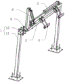
Fig. 1 is a perspective view of the automatic pushing plate mechanism of the present invention.
Fig. 2 is a perspective view of the structure of the sliding seat connected to the moving rod in the automatic push plate mechanism of the present invention.
Fig. 3 is a perspective view of the structure of the push plate component in the automatic push plate mechanism provided by the present invention.
Fig. 4 is the utility model provides a sheet material feeder's schematic structure diagram.
Fig. 5 is a perspective view of a structure of the pallet loading platform in the board feeding machine provided by the present invention.
Fig. 6 is a first perspective view of a material preparation table in the plate feeding machine provided by the present invention.
Fig. 7 is a perspective view of a material preparing platform in the plate feeding machine provided by the present invention.
Detailed Description
The utility model provides an automatic push pedal mechanism and panel feeder thereof, for making the utility model discloses a purpose, technical scheme and effect are clearer, clear and definite, and it is right that the following refers to the drawing and the embodiment of lifting is the utility model discloses further detailed description. It should be understood that the specific embodiments described herein are for purposes of illustration only and are not intended to limit the invention.
Referring to fig. 1 and 3, the present invention provides an automatic push plate mechanism, which includes a support 1, a moving rod 2 disposed on the support 1 and capable of moving horizontally relative to the support 1, and a plurality of push plate members 4 disposed on the moving rod 2; the push plate component 4 comprises a mounting seat 41 fixed on the moving rod 2, a plurality of guide rods 42 arranged on the mounting seat 41 and capable of moving up and down relative to the mounting seat 41, and a pressing block 43 fixed at the bottom ends of the guide rods 42; the pressing block 43 is provided with a plurality of rollers 44 which can rotate and contact with the surface of the plate along the moving direction of the moving rod 2, and the rear end of the pressing block 43 is provided with a pushing block 45 for pushing the plate. In this embodiment, two push plate members 4 are provided on the moving rod 2, and more than two push plate members may be provided according to actual requirements. The two pusher members may be symmetrically disposed about the sheet centerline. Two mounting seats 41 are respectively fixed on two sides of the moving rod 2, the mounting seats can be fixedly connected to the moving rod through bolts, a guide rod 42 is slidably connected to each mounting seat, and more than one guide rod can be arranged on the mounting seats according to requirements. The top end of the guide rod is fixed with a limiting block 47 which can be a nut connected with the guide rod in a threaded mode or a metal block welded to the top end of the guide rod. Of course, it is also possible that both guide rods are mounted to the same mounting, which is fixed to the moving rod. The pushing block 45 is fixedly connected to the rear end of the pressing block 43 through bolts or welding. The pressing block 43 is in a cuboid shape, the top of the pressing block 43 is provided with an inverted T-shaped groove 46, the guide rod 42 slides into the groove from the front end of the pressing block, and the guide rod and the pressing block are tightly fixed by adopting a nut. Of course, the guide bar may also be welded to the press block.
Specifically, as shown in fig. 3, the front end of the pressing block 43 is provided with a chamfer. After the front end of briquetting and the trailing flank of panel contacted, because the design of chamfer, at the in-process that the carriage release lever removed, the briquetting moved up because of the guide effect of chamfer for the briquetting, the gyro wheel contacts with the panel top surface, and the briquetting continues to move forward along with the carriage release lever, and the gyro wheel rolls at the panel top surface, and the ejector pad of briquetting rear end contacts with the trailing flank of panel, and the ejector pad is followed and is removed along with the carriage release lever and promote panel.
Specifically, the support 1 is fixed with a first telescopic cylinder 3, and a piston rod of the first telescopic cylinder 3 drives the moving rod 2 to move horizontally. Of course, except using telescopic cylinder, can also use positive and negative motor and belt or chain to replace, let the carriage release lever be fixed in belt or chain, positive and negative motor work drives belt or chain and makes a round trip to rotate, realizes the round trip horizontal migration of carriage release lever.
Specifically, a piston rod of the first telescopic cylinder 3 is fixedly connected with a sliding seat 5, and the sliding seat 5 is slidably connected with the bracket 1; the movable rod 2 is arranged on the sliding seat 5.
Further, as shown in fig. 1 and 2, the sliding seat 5 is provided with a vertical rod 51, the vertical rod 51 is provided with a second telescopic cylinder 6 hinged thereto, and a piston rod of the second telescopic cylinder 6 is hinged to the moving rod 2; the moving rod 2 is hinged with the sliding seat 5. The vertical rod and the sliding seat are integrally formed or connected through bolts. Under the telescopic action of the second telescopic cylinder, the moving rod can be kept in a horizontal state or an inclined upward state, in the plate pushing process, a piston rod of the second telescopic cylinder extends to enable the moving rod to be kept horizontal, and then the moving rod moves horizontally along with the retraction action of a piston rod of the first telescopic cylinder to push a plate; after the plate pushing is finished, the next plate starts to be lifted to wait for being pushed; simultaneously, the piston rod retraction of the second telescopic cylinder orders about the movable rod to rotate around the hinged position of the movable rod and the sliding seat, so that the movable rod keeps inclining upwards, and then the piston rod of the first telescopic cylinder extends to enable the movable rod to reset quickly, and the pressing block cannot obstruct the rising plate in the resetting process, so that the process of the work of the pushing plate is accelerated.
Specifically, the support 1 includes two support rods 11 and a cross rod 12 with two ends fixed to the top ends of the two support rods 11 respectively, the cross rod 12 is sleeved with the sliding seat 5, and the first telescopic cylinder 3 is fixed on the cross rod 12. The rear end of the first telescopic cylinder is installed on the cross rod through a bolt.
Specifically, as shown in fig. 2, four sides of both ends of the sliding seat 5 are respectively provided with openings 52, and the sliding seat 5 is provided with a pulley 53 contacting with a side of the crossbar 12 corresponding to each opening 52. The sliding seat is hollow and sleeved on the cross rod, a pulley 53 is arranged on the sliding seat corresponding to each opening by arranging eight openings 52, and when the sliding seat slides back and forth relative to the cross rod, the eight pulleys are all contacted with the side surface of the cross rod, so that the sliding seat can slide stably and smoothly.
The automatic plate pushing mechanism can be used for pushing flat-plate-shaped substances such as plates, glass, ceramic tiles and the like, and is mainly used for pushing a base material of a melamine plate (also called a double-veneer) to a hot press or the next procedure in the production line of the melamine plate in the embodiment.
In addition, the utility model also provides a plate feeder, as shown in fig. 4, which comprises the automatic push plate mechanism 9, the plate lifting platform 7 and the material preparing platform 8; the plate lifting platform 7 is arranged at the rear side of the material preparing platform 8, and the material preparing platform conveys the piled plates 10 to the plate lifting platform; the bracket 1 of the automatic plate pushing mechanism 9 is arranged at the rear side of the plate lifting platform 7, and the moving rod 2 of the automatic plate pushing mechanism 9 is positioned at the left side of the plate 10.
The working process of the plate feeder comprises the following steps: a worker uses a forklift to place a plate 10 on the material preparation table 8, and when the plate lifting table 7 is in an idle and non-working state, a piston rod of a second telescopic cylinder of the automatic plate pushing mechanism 9 works to turn over the moving rod upwards so that the moving rod keeps an inclined and upward state; however, the plate is conveyed to the plate lifting platform in an empty state by the backup material platform, and the moving rod cannot block the plate in the conveying process. After panel is stably placed at the panel elevating platform, the carriage release lever overturns downwards under the work of second telescopic cylinder, keep the horizontality, and the gyro wheel under the briquetting contacts with the top surface of panel after the carriage release lever upset, the guide arm shifts up the height of adjusting the relative carriage release lever of gyro wheel by oneself, the piston rod withdrawal of first telescopic cylinder afterwards, drive carriage release lever horizontal migration, the gyro wheel rolls at the panel top surface along with the removal of carriage release lever, after the ejector pad of briquetting rear end contacts with the left surface of panel, the ejector pad promotes panel and moves to the right along with the removal of carriage release lever, with panel propelling movement to next process. After the push pedal work was accomplished to the ejector pad, the carriage release lever turned up under the drive of the flexible cylinder of second, then moved left under the drive of first flexible cylinder, and panel elevating platform work, lifting panel simultaneously to a panel under the automatic pushing mechanism propelling movement. Drive the carriage release lever through setting up the flexible cylinder of second and overturn up to make the lifting work of panel and the resetting of ejector pad can go on simultaneously, need not wait for and just carry out the panel lifting after the ejector pad resets, reduce the push pedal time that consumes greatly, promote work efficiency.
Specifically, as shown in fig. 5, the plate lifting platform includes a plate carrying platform and a lifting mechanism (not shown in the figure) disposed below the plate carrying platform and driving the plate carrying platform to lift; the plate loading platform comprises a frame 71, a plurality of groups of first rollers 72 which are rotatably arranged on the frame 71 and used for conveying plates, a first motor 74 which is arranged below the frame 71 and used for driving the first rollers 72 to rotate, a baffle 73 which is fixed at the rear side of the frame 71 and used for positioning the plates, a proximity switch (not shown in the figure) which is arranged at the rear side of the frame, and a control device (not shown in the figure) which is respectively electrically connected with the first motor, the proximity switch, a first telescopic cylinder and a second telescopic cylinder of the automatic plate pushing mechanism and a lifting mechanism. The bottom surface of the plate carrying table is fixedly connected with the top of the lifting mechanism, and the lifting mechanism works to drive the plate carrying table to move in the vertical direction, so that the lifting of the plates is realized.
In the process that the material preparation table conveys the plates to the plate lifting table, a first motor of the plate lifting table is in a working state and drives the roller to rotate; the proximity switch detects the position of the plate in real time, when the plate is detected to be in contact with the baffle, the proximity switch sends a signal to the control device, the control device controls the first motor to stop working, then controls the second telescopic cylinder to work, and places the moving rod horizontally so that the roller is in contact with the plate; and then, the first telescopic cylinder works to drive the movable rod to move rightwards. When the first telescopic cylinder moves in place, the control device sequentially controls the second telescopic cylinder and the first telescopic cylinder to work, the movable rod is turned upwards by the control device, and then the movable rod is reset; and then, the control device controls the lifting mechanism to work to lift the plate, and after the plate is lifted, the second telescopic cylinder works under the control of the control device to continuously push the next plate. In this embodiment, a lifting mechanism such as a hydraulic rod may be used to drive the support plate table to move up and down, so as to lift the plate.
It should be noted that three groups of rollers can be arranged on the plate loading table, each group of rollers is correspondingly driven to rotate by one first motor, and certainly, one motor can also be adopted, a transmission shaft is driven to rotate by the motor, and the three groups of rollers are driven to work by three chains. The rollers of each group are driven by chains. It should be understood that one or more sets of rollers may be provided to convey the sheet material, depending on the actual requirements. The baffle is designed to block the plate in the process of conveying the plate by the roller, so that the plate is prevented from falling off from the plate loading table or being positioned improperly, and a positioning effect is achieved. The height of the baffle can be designed according to the actual situation.
In addition, can set up pressure sensor at baffle department and replace proximity switch, touch pressure sensor when panel, let pressure sensor produce the signal to order about motor stop work, let the roller stop to roll, after having sent the bottommost panel, pressure sensor produces the signal again, orders about elevating system and descends, is convenient for place the panel that has piled up toward carrying the board bench, then orders about motor work, lets the roller rotatory. Except this, can also adopt limit switch to replace proximity switch, play the same effect, after panel touched limit switch, first roller stop work.
Specifically, as shown in fig. 6 and 7, the material preparing platform 8 includes a bottom frame 81, a plurality of heavy guide wheels 84 respectively disposed on the left and right sides of the bottom frame 81, three rows of short roller sets and one row of long roller sets disposed on the bottom frame 81, two forklift slots 82 disposed on the bottom frame 81 and between adjacent short roller sets, guide blocks 83 disposed on the front side of the bottom frame 81 and on both sides of the forklift slots 82, and a second motor 87 disposed below the bottom frame 81 and used for driving the three rows of short roller sets to rotate; each row of short roller group comprises a plurality of short rollers 85 arranged in parallel, and the adjacent short rollers 85 are connected through a chain; the long roller group comprises a plurality of long rollers 86 which are arranged in parallel, the adjacent long rollers 86 are connected through a chain, and the long roller at the forefront side is connected with the short roller at the rearmost side through a chain; the second motor 87 is electrically connected to the control device. The power shaft 88 is arranged below the bottom frame 81 in a rotating mode, the second motor 87 works to drive the power shaft 88 to rotate, the power shaft is installed on the bottom frame 81 through a bearing, the power shaft is respectively connected with the short roller chain on the foremost side of each row, the power shaft rotates to drive the short rollers to rotate at the same time, and the short rollers are used for conveying plates. The guide block is the metal block that is the V-arrangement, can be the iron plate, and when the staff drove fork truck and place panel on the material preparation bench, two forks of fork truck inserted the fork truck inslot via the guide block accuracy without mistake, then the fork slowly descends, made panel steadily fall on the material preparation bench, then can drive fork truck, take out the fork from the fork truck inslot. Underframe both sides are provided with rotatable heavy leading wheel, and heavy leading wheel, short roller and long roller support the panel that piles up jointly, have increased the lifting surface area of panel, slow down the pressure of panel to short roller and long roller, help the transport of panel.
To sum up, the utility model provides an automatic push pedal mechanism and panel feeder thereof, structural design is ingenious, and reliable stable, degree of automation is high, can high-efficiently accomplish the push pedal work. This automatic push pedal mechanism adopts first telescopic cylinder to drive the horizontal round trip movement of carriage release lever, and the push pedal part of locating the carriage release lever is along with the removal of carriage release lever and propelling movement panel, the mount pad vertical migration of push pedal part can be relative to the briquetting of push pedal part, when the push pedal part carries out the push pedal during operation, along with the removal of carriage release lever, the gyro wheel of locating the briquetting below contacts and takes place the roll with the panel top surface, then the ejector pad contacts with the panel side to promote panel next process. The staff adopts fork truck to send panel to the platform of prepareeing material, carries panel to the panel elevating platform when the panel elevating platform is in the vacancy, sets up the flexible cylinder of second and drives the carriage release lever and rotate, raises the briquetting, and the preparation platform of being convenient for sends panel to the panel elevating platform on, avoids hindering the removal of panel so that cause the influence to the platform work of prepareeing material. And, after automatic push pedal mechanism propelling movement panel, the flexible cylinder work of second overturns the carriage release lever up, and the panel elevating platform simultaneous working of being convenient for lifts panel, and then shortens the time that the push pedal consumed, raises the efficiency. In addition, the pressing block is arranged at the bottom end of the guide rod capable of sliding relative to the mounting seat, when the moving rod in an inclined state is adjusted to be in a horizontal state under the working of the second telescopic cylinder, the roller is pressed on the top surface of the plate, meanwhile, the guide rod can move upwards relatively to automatically adjust the height distance of the pressing block relative to the moving rod so as to deal with the situation that the thicknesses of the plates are different and the top surfaces of the plates are not horizontal, so that the roller of each pressing block can contact with the top surface of the plate, better contact between the pushing block and the plate is ensured, the contact area between the pushing block and the plate is increased, the pressure generated by the pushing block to the side surface of the plate is reduced, and the side surface of the plate is.
It should be understood that equivalent alterations and modifications can be made by those skilled in the art according to the technical solution of the present invention and the inventive concept thereof, and all such alterations and modifications should fall within the scope of the appended claims.
Claims (10)
1. An automatic push plate mechanism is characterized by comprising a bracket, a movable rod which is arranged on the bracket and can horizontally move relative to the bracket, and a plurality of push plate parts which are arranged on the movable rod; the push plate component comprises a mounting seat fixed on the moving rod, a plurality of guide rods arranged on the mounting seat and capable of moving up and down relative to the mounting seat, and a pressing block fixed at the bottom ends of the guide rods; the briquetting is equipped with a plurality of rotatable and with panel surface contact's gyro wheels along the moving direction of carriage release lever, and the rear end of briquetting is equipped with the ejector pad that is used for the push pedal.
2. The automatic push plate mechanism according to claim 1, wherein the front end of the press block is chamfered.
3. The automatic plate pushing mechanism according to claim 2, wherein the bracket is fixed with a first telescopic cylinder, and a piston rod of the first telescopic cylinder drives the movable rod to move horizontally.
4. The automatic push plate mechanism according to claim 3, wherein a sliding seat is fixedly connected to the piston rod of the first telescopic cylinder, and the sliding seat is slidably connected to the bracket; the movable rod is arranged on the sliding seat.
5. The automatic push plate mechanism according to claim 4, wherein the sliding seat is provided with a vertical rod, the vertical rod is provided with a second telescopic cylinder hinged with the vertical rod, and a piston rod of the second telescopic cylinder is hinged with the moving rod; the moving rod is hinged to the sliding seat.
6. The automatic plate pushing mechanism according to claim 5, wherein the support comprises two support rods and a cross rod having two ends fixed to the top ends of the two support rods, the sliding seat is sleeved on the cross rod, and the first telescopic cylinder is fixed to the cross rod.
7. The automatic plate pushing mechanism according to claim 6, wherein the sliding seat has openings on four sides of both ends thereof, and the sliding seat has a pulley contacting with a side of the cross bar corresponding to each opening.
8. A sheet feeder comprising the automatic pushing plate mechanism, a sheet lifting table and a stock preparation table according to any one of claims 1 to 7; the plate lifting platform is arranged on the rear side of the material preparation platform; the support of the automatic plate pushing mechanism is arranged on the rear side of the plate lifting platform.
9. The board feeding machine according to claim 8, wherein the board lifting platform comprises a board carrying platform and a lifting mechanism which is arranged below the board carrying platform and drives the board carrying platform to lift; the plate carrying platform comprises a frame, a plurality of groups of first rollers which are rotatably arranged on the frame and used for conveying plates, a first motor which is arranged below the frame and used for driving the first rollers to rotate, a baffle which is fixed at the rear side of the frame and used for positioning the plates, a proximity switch which is arranged at the rear side of the frame, and a control device which is respectively electrically connected with the first motor, the proximity switch, a first telescopic cylinder and a second telescopic cylinder of an automatic push plate mechanism and a lifting mechanism.
10. The sheet feeding machine according to claim 9, wherein the material preparing table comprises a bottom frame, a plurality of heavy guide wheels respectively arranged on the left and right sides of the bottom frame, three rows of short roller sets and one row of long roller sets arranged on the bottom frame, two forklift slots arranged on the bottom frame and positioned between the adjacent short roller sets, guide blocks arranged on the front side of the bottom frame and positioned on two sides of the forklift slots, and a second motor arranged below the bottom frame and used for driving the three rows of short roller sets to rotate; each row of short roller group comprises a plurality of short rollers arranged in parallel, and adjacent short rollers are connected through a chain; the long roller group comprises a plurality of long rollers arranged in parallel, the adjacent long rollers are connected through a chain, and the long roller at the forefront side is connected with the short roller at the rearmost side through a chain; the second motor is electrically connected with the control device.
Priority Applications (1)
| Application Number | Priority Date | Filing Date | Title |
|---|---|---|---|
| CN201921030516.5U CN210312414U (en) | 2019-07-04 | 2019-07-04 | Automatic push plate mechanism and plate feeding machine thereof |
Applications Claiming Priority (1)
| Application Number | Priority Date | Filing Date | Title |
|---|---|---|---|
| CN201921030516.5U CN210312414U (en) | 2019-07-04 | 2019-07-04 | Automatic push plate mechanism and plate feeding machine thereof |
Publications (1)
| Publication Number | Publication Date |
|---|---|
| CN210312414U true CN210312414U (en) | 2020-04-14 |
Family
ID=70148436
Family Applications (1)
| Application Number | Title | Priority Date | Filing Date |
|---|---|---|---|
| CN201921030516.5U Active CN210312414U (en) | 2019-07-04 | 2019-07-04 | Automatic push plate mechanism and plate feeding machine thereof |
Country Status (1)
| Country | Link |
|---|---|
| CN (1) | CN210312414U (en) |
Cited By (3)
| Publication number | Priority date | Publication date | Assignee | Title |
|---|---|---|---|---|
| CN111573132A (en) * | 2020-05-25 | 2020-08-25 | 北京闼闼同创工贸有限公司 | Material supplying and discharging device |
| CN113731883A (en) * | 2021-09-09 | 2021-12-03 | 晟通科技集团有限公司 | Template cleaning device |
| CN114888614A (en) * | 2022-07-04 | 2022-08-12 | 群策精密金属(苏州)有限公司 | Positioning and feeding equipment for numerical control machining center |
-
2019
- 2019-07-04 CN CN201921030516.5U patent/CN210312414U/en active Active
Cited By (3)
| Publication number | Priority date | Publication date | Assignee | Title |
|---|---|---|---|---|
| CN111573132A (en) * | 2020-05-25 | 2020-08-25 | 北京闼闼同创工贸有限公司 | Material supplying and discharging device |
| CN113731883A (en) * | 2021-09-09 | 2021-12-03 | 晟通科技集团有限公司 | Template cleaning device |
| CN114888614A (en) * | 2022-07-04 | 2022-08-12 | 群策精密金属(苏州)有限公司 | Positioning and feeding equipment for numerical control machining center |
Similar Documents
| Publication | Publication Date | Title |
|---|---|---|
| CN210312414U (en) | Automatic push plate mechanism and plate feeding machine thereof | |
| CN210937684U (en) | Automatic go up unloading laser cutting equipment | |
| CN111268444A (en) | Automatic stacking device in UV floor production | |
| CN111390087B (en) | Intelligent sucker rod manufacturing production line | |
| CN111674940A (en) | Intelligent furniture plate double-face drilling equipment and machining method | |
| CN116833590B (en) | Automatic feeding and discharging device suitable for laser cutting machine | |
| CN113479652A (en) | Intelligent automatic production line for sawing, stacking and conveying | |
| CN111942846B (en) | Automatic feeding equipment for automobile body pipe fittings | |
| CN210676787U (en) | Multi-station heating automatic feeding device | |
| CN215478387U (en) | Online hacking machine | |
| CN215905365U (en) | Automatic workpiece feeding device | |
| CN113716123B (en) | Automatic material sheet boxing device, production line and application thereof | |
| CN215749617U (en) | Copper foil stamping equipment of brazing type heat exchanger for residual heat of marine main engine | |
| CN213859738U (en) | Automatic unloader that goes up of plank | |
| CN215746108U (en) | Automatic unloading conveyor of reinforcing bar cutter | |
| CN210848557U (en) | Feeding mechanism of automatic pipe cutting system | |
| CN210795025U (en) | Stacking device capable of automatically feeding trays | |
| CN210548821U (en) | Full-automatic laser engraving device for engine cylinder ring | |
| CN211366045U (en) | Automatic feeding device for roller | |
| CN110153607B (en) | Automatic cutting device for steel plate | |
| CN217126115U (en) | Automatic feeding and discharging machine | |
| CN207451110U (en) | A kind of automotive drum type braking piece automatic piling accumulates device | |
| CN220481015U (en) | Transverse pushing feeding frame | |
| CN213504375U (en) | Step shaft feeder | |
| CN117163670B (en) | Stacking device for material distribution and transportation |
Legal Events
| Date | Code | Title | Description |
|---|---|---|---|
| GR01 | Patent grant | ||
| GR01 | Patent grant | ||
| CP01 | Change in the name or title of a patent holder |
Address after: 528137 Guangdong Province Sanshui District Leping Town Fanhu Economic Development Zone Yueshan Decoration Industry Co., Ltd. (Office Building) F1 (Residence Declaration) Patentee after: Guangdong Yueshan New Material Technology Co.,Ltd. Address before: 528137 Guangdong Province Sanshui District Leping Town Fanhu Economic Development Zone Yueshan Decoration Industry Co., Ltd. (Office Building) F1 (Residence Declaration) Patentee before: FOSHAN SANSHUI YUESHAN DECORATION INDUSTRIAL Co.,Ltd. |
|
| CP01 | Change in the name or title of a patent holder |