CN113686497B - Visual experimental device for researching pipeline flowing safe hydrate characteristics and leakage monitoring - Google Patents
Visual experimental device for researching pipeline flowing safe hydrate characteristics and leakage monitoring Download PDFInfo
- Publication number
- CN113686497B CN113686497B CN202110795705.7A CN202110795705A CN113686497B CN 113686497 B CN113686497 B CN 113686497B CN 202110795705 A CN202110795705 A CN 202110795705A CN 113686497 B CN113686497 B CN 113686497B
- Authority
- CN
- China
- Prior art keywords
- gas
- pressure
- stainless steel
- leakage
- valve
- Prior art date
- Legal status (The legal status is an assumption and is not a legal conclusion. Google has not performed a legal analysis and makes no representation as to the accuracy of the status listed.)
- Active
Links
- 238000012544 monitoring process Methods 0.000 title claims abstract description 17
- 230000000007 visual effect Effects 0.000 title claims description 19
- 239000007789 gas Substances 0.000 claims abstract description 100
- XLYOFNOQVPJJNP-UHFFFAOYSA-N water Substances O XLYOFNOQVPJJNP-UHFFFAOYSA-N 0.000 claims abstract description 80
- 239000007788 liquid Substances 0.000 claims abstract description 72
- VNWKTOKETHGBQD-UHFFFAOYSA-N methane Chemical compound C VNWKTOKETHGBQD-UHFFFAOYSA-N 0.000 claims abstract description 67
- 230000005540 biological transmission Effects 0.000 claims abstract description 25
- 238000011160 research Methods 0.000 claims abstract description 19
- 238000002156 mixing Methods 0.000 claims abstract description 18
- 239000003345 natural gas Substances 0.000 claims abstract description 13
- NMJORVOYSJLJGU-UHFFFAOYSA-N methane clathrate Chemical group C.C.C.C.O.O.O.O.O.O.O.O.O.O.O.O.O.O.O.O.O.O.O.O.O.O.O NMJORVOYSJLJGU-UHFFFAOYSA-N 0.000 claims abstract description 12
- 238000000926 separation method Methods 0.000 claims abstract description 10
- 230000008859 change Effects 0.000 claims abstract description 9
- 238000000354 decomposition reaction Methods 0.000 claims abstract description 8
- 238000012360 testing method Methods 0.000 claims abstract description 6
- 239000000203 mixture Substances 0.000 claims abstract description 4
- 229910001220 stainless steel Inorganic materials 0.000 claims description 70
- 239000010935 stainless steel Substances 0.000 claims description 70
- 238000000034 method Methods 0.000 claims description 27
- 239000011521 glass Substances 0.000 claims description 21
- 230000008569 process Effects 0.000 claims description 21
- 238000001035 drying Methods 0.000 claims description 9
- 238000012545 processing Methods 0.000 claims description 8
- 150000004677 hydrates Chemical class 0.000 claims description 7
- LYCAIKOWRPUZTN-UHFFFAOYSA-N Ethylene glycol Chemical compound OCCO LYCAIKOWRPUZTN-UHFFFAOYSA-N 0.000 claims description 6
- 230000001105 regulatory effect Effects 0.000 claims description 6
- 230000001276 controlling effect Effects 0.000 claims description 3
- 230000004660 morphological change Effects 0.000 claims description 2
- 239000008400 supply water Substances 0.000 claims 1
- 230000015572 biosynthetic process Effects 0.000 abstract description 11
- 239000008239 natural water Substances 0.000 abstract description 2
- 238000002474 experimental method Methods 0.000 description 15
- 230000000694 effects Effects 0.000 description 6
- 238000006243 chemical reaction Methods 0.000 description 5
- 238000004364 calculation method Methods 0.000 description 3
- 238000010586 diagram Methods 0.000 description 3
- 238000012800 visualization Methods 0.000 description 3
- 239000013078 crystal Substances 0.000 description 2
- 230000009467 reduction Effects 0.000 description 2
- 238000004088 simulation Methods 0.000 description 2
- 229910000831 Steel Inorganic materials 0.000 description 1
- 230000009471 action Effects 0.000 description 1
- 238000001816 cooling Methods 0.000 description 1
- 238000009792 diffusion process Methods 0.000 description 1
- 238000006073 displacement reaction Methods 0.000 description 1
- 239000012530 fluid Substances 0.000 description 1
- 230000009916 joint effect Effects 0.000 description 1
- 239000004973 liquid crystal related substance Substances 0.000 description 1
- 239000007791 liquid phase Substances 0.000 description 1
- 238000012423 maintenance Methods 0.000 description 1
- 238000005259 measurement Methods 0.000 description 1
- 238000010907 mechanical stirring Methods 0.000 description 1
- 238000012986 modification Methods 0.000 description 1
- 230000004048 modification Effects 0.000 description 1
- -1 natural gas hydrates Chemical class 0.000 description 1
- 230000033116 oxidation-reduction process Effects 0.000 description 1
- 239000005401 pressed glass Substances 0.000 description 1
- 230000010349 pulsation Effects 0.000 description 1
- 238000004064 recycling Methods 0.000 description 1
- 238000012827 research and development Methods 0.000 description 1
- 239000007787 solid Substances 0.000 description 1
- 230000006641 stabilisation Effects 0.000 description 1
- 238000011105 stabilization Methods 0.000 description 1
- 239000010959 steel Substances 0.000 description 1
- 239000013589 supplement Substances 0.000 description 1
- 238000012795 verification Methods 0.000 description 1
Images


Classifications
-
- G—PHYSICS
- G01—MEASURING; TESTING
- G01M—TESTING STATIC OR DYNAMIC BALANCE OF MACHINES OR STRUCTURES; TESTING OF STRUCTURES OR APPARATUS, NOT OTHERWISE PROVIDED FOR
- G01M3/00—Investigating fluid-tightness of structures
- G01M3/02—Investigating fluid-tightness of structures by using fluid or vacuum
Landscapes
- Physics & Mathematics (AREA)
- General Physics & Mathematics (AREA)
- Pipeline Systems (AREA)
- Examining Or Testing Airtightness (AREA)
Abstract
本发明公开了一种用于管道流动安全水合物特性研究及泄露监测的可视化实验装置,包括输气系统,用于提供天然气且能连续供给;输水系统,用于储存水源且能连续供给;气液混合系统,用于在常温下提前将天然气和水源进行混合;模型主体系统或泄露系统,所述模型主体系统用于研究低温条件下天然气水合物生成、分解过程中动力学特性和观测宏观形态变化;所述泄露系统用于监测试验管段在水下泄露情况,从而得到水下泄漏气体的泄露规律;回压系统,用于降低环路出口压力;气液分离系统,用于将气液混合物予以分离;回气系统,用于回收分离出的天然气,保证气体能够循环利用;本发明能够实现实验室条件下研究水合物的特性与监测管道气体泄漏。
The invention discloses a visualized experimental device for pipeline flow safety hydrate characteristic research and leakage monitoring, comprising a gas transmission system for supplying natural gas and continuous supply; and a water transmission system for storing water source and capable of continuous supply; The gas-liquid mixing system is used to mix natural gas and water sources in advance at normal temperature; the model main system or leakage system is used to study the dynamic characteristics and observe the macroscopic observation during the formation and decomposition of natural gas hydrate under low temperature conditions. The shape change; the leakage system is used to monitor the underwater leakage of the test pipe section, so as to obtain the leakage rule of the underwater leaking gas; the back pressure system is used to reduce the loop outlet pressure; the gas-liquid separation system is used to separate the gas and liquid The mixture is separated; the gas return system is used to recover the separated natural gas to ensure that the gas can be recycled; the invention can realize the research on the characteristics of hydrate and the monitoring of pipeline gas leakage under laboratory conditions.
Description
技术领域technical field
本发明涉及一种水合物管道环路实验装置,具体涉及一种用于管道流动安全水合物特性研究及泄露监测的可视化实验装置。The invention relates to a hydrate pipeline loop experiment device, in particular to a visual experiment device used for the research of pipeline flow safety hydrate characteristics and leakage monitoring.
背景技术Background technique
天然气水合物是指天然气(通常以甲烷为主)与水在低温和高压下生成的一种笼形结构固态晶体,在海域与冻土区均有广泛的分布。水合物作为一种储量巨大、洁净的新型替代能源受到普遍关注。随着水合物研究的日益深入,特别是天然气水合物特性方面的研究与发展,天然气水合物储运、混合气体分离等方面的应用前景日益显现。管道输运具有连续高效、安全稳定、经济无污染等优点,但实际输运条件较为恶劣,容易出现管道气体泄漏的情况。一旦发生泄漏,不仅造成较大的经济损失,还会对人身安全造成威胁。因此,对油气集输管道中天然气水合物的生成、分解等过程的特性与泄漏的研究尤为重要,而其变化过程则需要可视化装置进行多维度研究。Natural gas hydrate refers to a cage-like structure solid crystal formed by natural gas (usually mainly methane) and water at low temperature and high pressure, and is widely distributed in sea areas and permafrost regions. Hydrates have attracted widespread attention as a new and clean alternative energy with huge reserves. With the deepening of hydrate research, especially the research and development of the characteristics of natural gas hydrate, the application prospects of natural gas hydrate storage and transportation, mixed gas separation, etc. are increasingly emerging. Pipeline transportation has the advantages of continuous efficiency, safety and stability, economical and pollution-free, etc. However, the actual transportation conditions are relatively poor, and pipeline gas leakage is prone to occur. Once leakage occurs, it will not only cause great economic losses, but also threaten personal safety. Therefore, it is particularly important to study the characteristics and leakage of natural gas hydrate formation and decomposition in oil and gas gathering and transportation pipelines, and the change process requires a multi-dimensional study of visualization devices.
目前,实验室多采用机械搅拌的方式来研究天然气水合物的特性,但是现有的实验装置存在反应容积小、可视范围有限、运行费用昂贵等缺点,无法观测到整个天然气水合物形成晶体结构和形貌的变化。相比于反应釜,在流动环路中开展水合物生成实验,能够模拟管输流动体系中水合物的生成规律,因此得到国内外众多研究者的青睐。此外,目前控温手段多采用管夹套的形式,其控温效果不够理想且导致管道可视面积减小,拍摄设备多设置在管道内部,由于管道大多由圆弧状管道相连接,导致拍摄效果会发生变形失真。同时,采用水平布置的环道致使设备占地面积过大,维护成本较高。目前仅有少数学者开展了一些小型的实验环路水合物特性的研究工作,但由于所使用的设备、介质、条件均不相同,在理论上还没有达成共识,有关天然气水合物特性研究并且通过实验环路的形式的文献不是很多。现有水下管道泄漏的研究主要是理论计算和数值模拟,实验室内模拟管道泄露的实验装置较少,测试起来具有一定的误差,因此在这方面的研究工作亟待深入。At present, most laboratories use mechanical stirring to study the characteristics of natural gas hydrates. However, the existing experimental devices have shortcomings such as small reaction volume, limited visual range, and high operating costs, and it is impossible to observe the formation of crystal structures of the entire natural gas hydrate. and shape changes. Compared with the reactor, the hydrate formation experiment carried out in the flow loop can simulate the formation rule of hydrate in the pipeline flow system, so it is favored by many researchers at home and abroad. In addition, the current temperature control method mostly adopts the form of pipe jacket, the temperature control effect is not ideal and the visible area of the pipe is reduced, and the shooting equipment is mostly installed inside the pipe. The effect will be distorted. At the same time, the use of horizontally arranged loops results in an excessively large area of equipment and high maintenance costs. At present, only a few scholars have carried out some small experimental researches on the characteristics of loop hydrates. However, due to the different equipment, media and conditions used, no consensus has been reached in theory. There is not much literature in the form of experimental loops. The existing research on underwater pipeline leakage is mainly based on theoretical calculation and numerical simulation. There are few experimental devices for simulating pipeline leakage in the laboratory, and there are certain errors in testing. Therefore, the research work in this area needs to be deepened.
发明内容SUMMARY OF THE INVENTION
针对现有技术存在上述问题,本申请提供一种用于管道流动安全水合物特性研究及泄露监测的可视化实验装置,其能够实现实验室条件下研究水合物的特性与监测管道气体泄漏,且整个过程全可视,这对于总结研究管道流动安全水合物特性的规律和气体泄露规律有着重要的作用。In view of the above-mentioned problems in the prior art, the present application provides a visual experimental device for the study of pipeline flow safety hydrate characteristics and leakage monitoring, which can realize the research on the characteristics of hydrate and the monitoring of pipeline gas leakage under laboratory conditions. The process is fully visible, which plays an important role in summarizing and studying the law of safe hydrate characteristics in pipeline flow and the law of gas leakage.
为实现上述目的,本申请的技术方案为:一种用于管道流动安全水合物特性研究及泄露监测的可视化实验装置,包括:In order to achieve the above purpose, the technical solution of the present application is: a visual experimental device used for the research of pipeline flow safety hydrate characteristics and leakage monitoring, including:
输气系统,用于提供天然气且能连续供给;Gas transmission system for supplying natural gas and continuous supply;
输水系统,用于储存水源且能连续供给;Water delivery system to store water and supply it continuously;
气液混合系统,分别与所述输气系统、输水系统相连,用于在常温下提前将天然气和水源进行混合;a gas-liquid mixing system, which is respectively connected with the gas transmission system and the water transmission system, and is used to mix natural gas and water source in advance at normal temperature;
模型主体系统或泄露系统,所述模型主体系统与所述气液混合系统相连,用于研究低温条件下天然气水合物生成、分解过程中动力学特性和观测宏观形态变化;所述泄露系统与所述气液混合系统相连,用于监测试验管段在水下泄露情况,从而得到水下泄漏气体的泄露规律;The model main body system or leakage system, the model main body system is connected with the gas-liquid mixing system, and is used to study the dynamic characteristics and observe the macroscopic morphological changes during the formation and decomposition of natural gas hydrate under low temperature conditions; The gas-liquid mixing system is connected to the above-mentioned gas-liquid mixing system, which is used to monitor the leakage of the test pipe section under water, so as to obtain the leakage rule of the gas leaking underwater;
回压系统,与所述模型主体系统或所述泄露系统相连,用于降低环路出口压力;a back pressure system, connected with the model body system or the leakage system, for reducing the loop outlet pressure;
气液分离系统,与所述回压系统相连,用于将气液混合物予以分离;a gas-liquid separation system, connected with the back pressure system, for separating the gas-liquid mixture;
回气系统,与所述气液分离系统相连,用于回收分离出的天然气,保证气体能够循环利用;a gas return system, connected with the gas-liquid separation system, for recovering the separated natural gas to ensure that the gas can be recycled;
温度控制系统,用于为模型主体系统提供低温环境;The temperature control system is used to provide a low temperature environment for the model body system;
数据采集处理系统,用于采集、处理、保存和分析天然气水合物在生成以及分解过程中各参数的变化规律。The data acquisition and processing system is used to acquire, process, save and analyze the variation law of each parameter during the formation and decomposition of natural gas hydrate.
进一步的,所述输气系统包括依次连通的高压甲烷气瓶、流量控制器,在所述高压甲烷气瓶与流量控制器之间的管道上设置有减压阀和截止阀,所述截止阀与止回阀a之间的管道上设置有安全阀;其流量控制器用于控制进入到环路内气体量。Further, the gas transmission system includes a high-pressure methane cylinder and a flow controller that are communicated in sequence, and a pressure reducing valve and a stop valve are arranged on the pipeline between the high-pressure methane cylinder and the flow controller, and the cut-off valve is provided. A safety valve is arranged on the pipeline between it and the check valve a; its flow controller is used to control the amount of gas entering the loop.
进一步的,所述输水系统包括依次连通的不锈钢刻度线水箱、AR循环泵、缓冲罐,所述缓冲罐与止回阀b之间的管路上安装有截止阀、背压阀;其中,不锈钢刻度线水箱通过体积法计量水量。Further, the water delivery system includes a stainless steel scale water tank, an AR circulating pump, and a buffer tank that are connected in sequence, and a stop valve and a back pressure valve are installed on the pipeline between the buffer tank and the check valve b; The tick tank measures the amount of water by volumetric method.
进一步的,所述气液混合系统包括气液混合器,该气液混合器入口通过管道分别与输气系统、输水系统连接,与输气系统相连的管道上设有止回阀a,与输水系统相连的管道上设有止回阀b;所述气液混合器出口通过压力传感器、温度传感器与模型主体系统或泄露系统相连,所述压力传感器、温度传感器位于两个截止阀之间。Further, the gas-liquid mixing system includes a gas-liquid mixer, the inlet of the gas-liquid mixer is respectively connected with the gas transmission system and the water transmission system through pipelines, and the pipeline connected with the gas transmission system is provided with a check valve a, which is connected with the gas transmission system. There is a check valve b on the pipeline connected to the water delivery system; the outlet of the gas-liquid mixer is connected to the model main system or the leakage system through a pressure sensor and a temperature sensor, and the pressure sensor and temperature sensor are located between the two stop valves .
进一步的,所述模型主体系统包括位于全透明控温水浴槽内的不锈钢盘旋弯管、可视盲管、主体结构和不锈钢输出管,所述不锈钢盘旋弯管顶部与气液混合系统相连,底部依次通过压力传感器、温度传感器、可视盲管、安全阀与主体结构入口相连,该主体结构出口与不锈钢输出管连接,所述主体结构包括由定位板进行定位的多段全透明耐压玻璃直管,相邻两个所述全透明耐压玻璃直管的首尾由不锈钢弯管连接。Further, the model main body system includes a stainless steel spiral elbow, a visible blind pipe, a main structure and a stainless steel output pipe located in a fully transparent temperature-controlled water bath. The top of the stainless steel spiral elbow is connected to the gas-liquid mixing system, and the bottom The main structure is connected to the inlet of the main structure through a pressure sensor, a temperature sensor, a visual blind pipe and a safety valve in turn, and the outlet of the main structure is connected to the stainless steel output pipe. The main structure includes a multi-section fully transparent pressure-resistant glass straight pipe positioned by a positioning plate , the head and tail of the two adjacent full transparent pressure-resistant glass straight pipes are connected by stainless steel elbows.
更进一步的,所述泄露系统包括位于全透明控温水浴槽内的不锈钢盘旋弯管、可视盲管、主体结构和不锈钢输出管,所述不锈钢盘旋弯管顶部与气液混合系统相连,底部通过可视盲管与主体结构入口相连,该主体结构出口与不锈钢输出管连接,所述主体结构包括由定位板进行定位的多段不锈钢耐压直管,相邻两个所述不锈钢耐压直管的首尾由不锈钢弯管连接,位于顶层和底层之间的不锈钢耐压直管均通过三通与对应的防水电磁阀,在该防水电磁阀两侧分别交替设有压力传感器和温度传感器。可通过控制防水电磁阀调节气体通过三通的气体量。Further, the leakage system includes a stainless steel coiled elbow, a visible blind pipe, a main structure and a stainless steel output pipe located in a fully transparent temperature-controlled water bath. The top of the stainless steel coiled elbow is connected to the gas-liquid mixing system, and the bottom The main structure is connected to the inlet of the main structure through a visible blind pipe, and the outlet of the main structure is connected to the stainless steel output pipe. The main structure includes a multi-section stainless steel pressure-resistant straight pipe positioned by a positioning plate, and two adjacent stainless steel pressure-resistant straight pipes are The head and tail are connected by stainless steel elbows. The stainless steel pressure-resistant straight pipes located between the top and bottom layers pass through the tee and the corresponding waterproof solenoid valve. Pressure sensors and temperature sensors are alternately arranged on both sides of the waterproof solenoid valve. The amount of gas passing through the tee can be adjusted by controlling the waterproof solenoid valve.
更进一步的,所述温度控制系统包括位于全透明控温水浴槽中的循环介质乙二醇,其采用外循环介质形式,该全透明控温水浴槽为上开盖的长方体结构,其由耐压玻璃制作而成。Further, the temperature control system includes a circulating medium ethylene glycol located in a fully transparent temperature-controlled water bath, which adopts the form of an external circulation medium. Made of pressed glass.
更进一步的,所述回压系统包括依次连通的回压阀、缓冲罐、自动回压泵,所述模型主体系统或所述泄露系统依次通过截止阀、压力传感器、温度传感器与回压阀相连,该回压阀还与气液分离器入口相连,所述气液分离器第一出口依次通过液体流量计、截止阀连回至不锈钢刻度线水箱,在回压阀与缓冲罐之间的管道上设置有截止阀,在缓冲罐与自动回压泵之间的管道上也设置有截止阀。Further, the back pressure system includes a back pressure valve, a buffer tank, and an automatic back pressure pump that are communicated in sequence, and the model body system or the leakage system is sequentially connected to the back pressure valve through a stop valve, a pressure sensor, and a temperature sensor. , the back pressure valve is also connected to the inlet of the gas-liquid separator, the first outlet of the gas-liquid separator is connected to the stainless steel scale water tank through the liquid flow meter and the stop valve in turn, and the pipeline between the back pressure valve and the buffer tank There is a cut-off valve on the upper part, and a cut-off valve is also set on the pipeline between the buffer tank and the automatic back pressure pump.
作为更进一步的,所述回气系统包括干燥管、气体流量计、增压泵Ⅰ、增压泵Ⅱ、驱动调压阀、空压机、甲烷储气罐,所述干燥管一端与气液分离器第二出口相连,另一端依次通过气体流量计、截止阀、增压泵Ⅰ连接至增压泵Ⅱ,所述增压泵Ⅰ与增压泵Ⅱ串联并分别通过截止阀、驱动调压阀连接至空压机,所述增压泵Ⅱ还通过甲烷储气罐、止回阀、截止阀连回至减压阀。采用串联的方式可保证回气有相应的压力值,使得回气顺利,利于气体的重复利用。As a further example, the air return system includes a drying pipe, a gas flow meter, a booster pump I, a booster pump II, a driving pressure regulating valve, an air compressor, and a methane gas storage tank. One end of the drying pipe is connected to the gas-liquid The second outlet of the separator is connected, and the other end is connected to the booster pump II through a gas flow meter, a stop valve, and a booster pump I in sequence. The valve is connected to the air compressor, and the booster pump II is also connected to the pressure reducing valve through a methane gas storage tank, a check valve and a stop valve. The series connection can ensure that the return gas has a corresponding pressure value, so that the return gas is smooth, which is conducive to the reuse of the gas.
作为更进一步的,所述数据采集处理系统,包括拍摄装置,该拍摄装置正对着全透明控温水浴槽内的模型主体系统或泄露系统的主体结构,实时进行高清拍摄。As a further aspect, the data acquisition and processing system includes a photographing device, and the photographing device is facing the model main body system or the main structure of the leakage system in the fully transparent temperature-controlled water bath, and performs high-definition photography in real time.
本发明由于采用以上技术方案,能够取得如下的技术效果:The present invention can obtain the following technical effects due to the adoption of the above technical solutions:
1、采用气液混合器作为发生装置,可将实验气体与实验液体按预定比例混合为实验介质,提高天然气水合物生成速度。1. The gas-liquid mixer is used as the generating device, and the experimental gas and the experimental liquid can be mixed into the experimental medium according to a predetermined ratio, so as to improve the formation speed of natural gas hydrate.
2、模型主体系统与泄露系统之间转换方便,可实现一套实验装置做两个实验。2. The conversion between the model main system and the leakage system is convenient, and a set of experimental devices can be realized to do two experiments.
3、采用不锈钢刻度线水箱作为储水装置,可以清楚地观测到整个水箱内水源的体积变化。3. The stainless steel scale water tank is used as the water storage device, and the volume change of the water source in the entire water tank can be clearly observed.
4、不锈钢弯管经过盘旋,可延长气液混合物预冷的管路,不锈钢弯管置于全透明控温水浴槽内,可节省再次设置低温水浴为输气系统输送出来的气体或者输水系统输送的水进行预冷,更加经济方便。4. The coiled stainless steel elbow can extend the pre-cooling pipeline of the gas-liquid mixture. The stainless steel elbow is placed in a fully transparent temperature-controlled water bath, which can save the gas or water delivery system by setting up a low-temperature water bath again for the gas transmission system. The transported water is pre-cooled, which is more economical and convenient.
5、本发明模型主体系统中全透明耐压玻璃直管段采用垂直向上排列,由于采用全透明耐压玻璃,每段可视化反应管段可达1000mm,不仅节约水平空间还方便观察者进行观察水合物的状态,能提供更直观的研究效果。控温水浴槽全部采用全透明玻璃制造而成,大大增加了可视视野。主体结构入口处设置有安全阀,更能保证实验的安全性。5. The straight pipe sections of the fully transparent pressure-resistant glass in the main system of the model of the present invention are arranged vertically upward. Due to the use of fully transparent pressure-resistant glass, each visual reaction tube section can reach 1000 mm, which not only saves horizontal space but also facilitates the observer to observe the hydrate. status, which can provide a more intuitive research effect. The temperature-controlled water baths are all made of fully transparent glass, which greatly increases the visual field of view. There is a safety valve at the entrance of the main structure, which can better ensure the safety of the experiment.
6、所述拍摄设备正对全透明控温水浴槽,采集数据光线更加充足,无需设置探照灯,便于移动,操作更加简单方便,可为复杂的管道流动水合物学特性分析提供更加清晰的图像。6. The photographing equipment is facing the fully transparent temperature-controlled water bath, and the light for collecting data is more abundant, no searchlight is required, it is easy to move, the operation is simpler and more convenient, and it can provide clearer images for the analysis of complex pipeline flow hydrate characteristics.
7、本发明能够满足实验室当前在水下气体管道泄漏方面的研究需求,为理论计算与数值模拟提供验证途径,提高其可信度。7. The present invention can meet the current research needs of the laboratory on the leakage of underwater gas pipelines, provide a verification method for theoretical calculation and numerical simulation, and improve its credibility.
附图说明Description of drawings
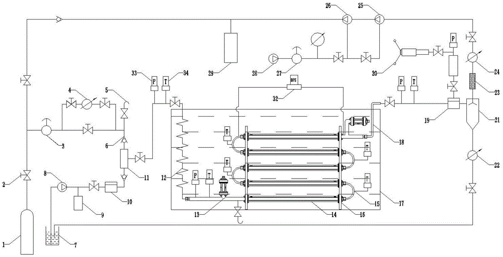
图1为可视化实验装置原理结构图;Fig. 1 is the principle structure diagram of the visual experiment device;
图2为全透明控温水浴槽和模型主体系统连接结构图。Figure 2 is the connection structure diagram of the fully transparent temperature-controlled water bath and the model main body system.
图3为全透明控温水浴槽和泄漏系统连接结构图;Figure 3 is the connection structure diagram of the fully transparent temperature-controlled water bath and the leakage system;
图中序号说明:1、高压甲烷气瓶;2、截止阀;3、减压阀;4、流量控制器;5、安全阀;6、止回阀a;7、不锈钢刻度线水箱;8、AR循环泵;9、缓冲罐;10、背压阀;11、气液混合器;12、不锈钢盘旋弯管;13、可视盲管;14、全透明耐压玻璃直管;15、不锈钢弯管;16、定位板;17、全透明控温水浴槽;18、不锈钢输出管;19、回压阀;20、自动回压泵;21、气液分离器;22、液体流量计;23、干燥管;24气体流量计;25、增压泵Ⅰ;26、增压泵Ⅱ;27、驱动调压阀;28、空压机;29、甲烷储气罐;30、CMOS高清相机;31、底座;32、差压传感器;33、压力传感器;34、温度传感器;35、防水电磁阀;36、可拆卸活接。Description of the serial numbers in the figure: 1. High pressure methane gas cylinder; 2. Globe valve; 3. Pressure reducing valve; 4. Flow controller; 5. Safety valve; 6. Check valve a; 7. Stainless steel scale water tank; 8. AR circulating pump; 9. Buffer tank; 10. Back pressure valve; 11. Gas-liquid mixer; 12. Stainless steel coiled elbow; 13. Visual blind pipe; 14. Fully transparent pressure-resistant glass straight pipe; 15. Stainless steel elbow Pipe; 16, positioning plate; 17, fully transparent temperature-controlled water bath; 18, stainless steel output pipe; 19, back pressure valve; 20, automatic back pressure pump; 21, gas-liquid separator; 22, liquid flow meter; 23, Drying pipe; 24 Gas flow meter; 25, Booster pump I; 26, Booster pump II; 27, Drive pressure regulating valve; 28, Air compressor; 29, Methane gas storage tank; 30, CMOS high-definition camera; 31, Base; 32, differential pressure sensor; 33, pressure sensor; 34, temperature sensor; 35, waterproof solenoid valve; 36, detachable union.
具体实施方式Detailed ways
本发明的实施例是在以本发明技术方案为前提下进行实施的,给出了详细的实施方式和具体的操作过程,但本发明的保护范围不限于下述实施例。The embodiments of the present invention are implemented on the premise of the technical solutions of the present invention, and detailed implementations and specific operation procedures are given, but the protection scope of the present invention is not limited to the following embodiments.
实施例1Example 1
如图1-3所示,本实施例提供一种用于管道流动安全水合物特性研究及泄露监测的可视化实验装置,包括输气系统、输水系统、气液混合系统、模型主体系统、泄漏系统、气液分离系统、回压系统、温度控制系统、回气系统、数据采集处理系统。As shown in Figures 1-3, this embodiment provides a visual experimental device for the study of pipeline flow safety hydrate characteristics and leakage monitoring, including a gas transmission system, a water transmission system, a gas-liquid mixing system, a model main system, and a leakage system, gas-liquid separation system, back pressure system, temperature control system, gas return system, data acquisition and processing system.
其中,模型主体系统包括不锈钢盘旋弯管、可视盲管、主体结构和不锈钢输出管,所述主体结构包括不锈钢弯管和全透明耐压玻璃直管,所述全透明耐压玻璃直管14优选4-6段均水平设置且垂直向上排列;不锈钢盘旋弯管12的尾端与第一段全透明耐压管段14之间通过不锈钢直管相连接,该不锈钢直管上设置有温度传感器、压力传感器、可视盲管13与安全阀,可视盲管与不锈钢直管为垂直关系,用来观测水合物遇到封闭管段时的特征状态,安全阀用来能够进一步保障进入全透明耐压直管段14的混合介质压力不会过冲。相邻全透明耐压直管之间通过不锈钢弯管15进行连接,其中每个不锈钢弯管15上设置有温度传感器,另外顶部的全透明耐压玻璃直管前后两段设置有差压传感器32。由不锈钢直管、全透明耐压玻璃直管14以及不锈钢弯管所连接而成的结构主体S形管段被固定在定位板16上,保证放置在全透明控温水浴槽17内不会晃动。本实施例中不锈钢盘旋弯管12、不锈钢直管具有高压条件下不变形、抗氧化还原性的能力,其中,不锈钢盘旋弯管12可以盘旋8圈,有效地对混合介质进行预冷,提高天然气水合物在全透明耐压玻璃直管14的生成率,不锈钢盘旋弯管12设置在全透明控温水浴槽17的内部,与结构主体共用一个低温水浴,既方便又经济,其耐压范围为0.01Mpa~10Mpa。全透明耐压玻璃直管14内径可达18mm,单段管长可为1000mm,工作压力范围可为0.01Mpa~6Mpa。另外,该模型主体系统的拆卸极其方便,将全透明控温水浴槽17封盖上端所连接的两个截止阀关闭即可将整体管路从全透明控温水浴槽17内拿出,便于更换其他类型的管道进行水合物研究实验。The model main body system includes a stainless steel spiral bend, a blind tube, a main structure and a stainless steel output pipe. The main structure includes a stainless steel bend and a fully transparent pressure-resistant glass straight pipe. The fully transparent pressure-resistant glass straight pipe 14 Preferably, the 4-6 sections are arranged horizontally and vertically upward; the tail end of the stainless steel coiled elbow 12 and the first full transparent pressure-resistant pipe section 14 are connected by a stainless steel straight pipe, and the stainless steel straight pipe is provided with a temperature sensor, Pressure sensor, visual blind pipe 13 and safety valve. The visual blind pipe and stainless steel straight pipe are in a vertical relationship, which are used to observe the characteristic state of hydrate when it encounters a closed pipe section. The mixed medium pressure in the straight pipe section 14 will not overshoot. The adjacent fully transparent pressure-resistant straight pipes are connected by stainless steel elbows 15, wherein each stainless steel elbow 15 is provided with a temperature sensor, and the front and rear two sections of the fully transparent pressure-resistant glass straight pipe at the top are provided with differential pressure sensors 32. . The S-shaped pipe section of the structural main body connected by the stainless steel straight pipe, the fully transparent pressure-resistant glass straight pipe 14 and the stainless steel elbow is fixed on the positioning plate 16 to ensure that it will not shake when placed in the fully transparent temperature-controlled water bath 17 . In this embodiment, the stainless steel convoluted pipe 12 and the stainless steel straight pipe have the ability of no deformation under high pressure and oxidation-reduction resistance. The stainless steel convoluted pipe 12 can be circled 8 times, which can effectively pre-cool the mixed medium and increase the natural gas The formation rate of hydrate in the fully transparent pressure-resistant glass straight tube 14. The stainless steel coiled elbow 12 is arranged inside the fully transparent temperature-controlled water bath 17, and shares a low-temperature water bath with the main body of the structure, which is convenient and economical. Its pressure resistance range is 0.01Mpa~10Mpa. The inner diameter of the fully transparent pressure-resistant glass straight tube 14 can reach 18mm, the length of a single section can be 1000mm, and the working pressure range can be 0.01Mpa ~ 6Mpa. In addition, the disassembly of the main body system of the model is extremely convenient. The entire pipeline can be taken out from the transparent temperature-controlled water bath 17 by closing the two stop valves connected to the upper end of the cover of the fully transparent temperature-controlled water bath 17, which is convenient for replacement. Other types of pipelines are used for hydrate research experiments.
泄漏系统的主体结构包括不锈钢耐压直管和不锈钢弯管,将模型主体系统取出后,通过可拆卸活接36把所有全透明耐压玻璃直管14由不锈钢耐压直管18替换。位于顶部与底部之间的不锈钢耐压直管上分别设置有防水电磁阀35以及顺序交替排列的温度传感器和压力传感器。此时放置回全透明控温水浴槽17内便可进行水下管道气体泄漏的实验研究。The main structure of the leakage system includes stainless steel pressure-resistant straight pipes and stainless steel elbows. After taking out the model main body system, all fully transparent pressure-resistant glass straight pipes 14 are replaced by stainless steel pressure-resistant straight pipes 18 through
由上述管段所构成的整体管道系统设置于全透明控温水浴槽17内,通过低温恒温循环器对其进行温度控制,形成温度控制系统。低温恒温循环器上设置有液晶显示器,内部设置有温度传感器,通过温度传感器实时反馈温度并进行调节。低温恒温循环器的循环量为100L/min,工作温度范围为-20℃~常温,控温精度为±0.5℃,容积为500L,可保证全透明控温水浴槽17内的温度从常温将至-10℃所需时间小于20min。全透明控温水浴槽整体固定在底座31上,其正面外侧设置有CMOS高清相机30,以便于对全透明耐压玻璃直管14内部进行观测和录像。The overall piping system formed by the above-mentioned pipe sections is arranged in the fully transparent temperature-controlled water bath 17, and its temperature is controlled by a low-temperature constant temperature circulator to form a temperature control system. A liquid crystal display is arranged on the low temperature thermostatic circulator, and a temperature sensor is arranged inside, and the temperature is fed back and adjusted in real time through the temperature sensor. The circulation volume of the low temperature constant temperature circulator is 100L/min, the working temperature range is -20°C to normal temperature, the temperature control accuracy is ±0.5°C, and the volume is 500L, which can ensure that the temperature in the fully transparent temperature-controlled water bath 17 is from normal temperature to The time required for -10℃ is less than 20min. The fully transparent temperature-controlled water bath is integrally fixed on the
输气系统包括依次连接的高压甲烷气瓶1、截止阀2、减压阀3、流量控制器4、安全阀5;上述各设备之间通过辅助管道相连接,其中,流量控制器4左右两端设置有截止阀,且并联在管道上,最大可耐压10Mpa,精度为±1%F.S,量程为20000SCCM。输气系统与回气系统共用一个减压阀3,通过减压阀3可进行减压调节,将高压甲烷气瓶1和甲烷储气罐29输出的气体调节到实验所需要的压力状态,安全阀5的设置可保证环路整体运行的安全。The gas transmission system includes a high-pressure methane gas cylinder 1, a stop valve 2, a pressure reducing valve 3, a flow controller 4, and a safety valve 5, which are connected in sequence; There is a stop valve at the end, and it is connected in parallel with the pipeline, the maximum pressure is 10Mpa, the accuracy is ±1%F.S, and the range is 20000SCCM. The gas transmission system and the gas return system share a pressure reducing valve 3, and the pressure reducing valve 3 can be used for pressure reduction adjustment, and the gas output from the high-pressure methane gas cylinder 1 and the methane gas storage tank 29 can be adjusted to the pressure state required by the experiment, which is safe The setting of valve 5 can ensure the safety of the overall operation of the loop.
输水系统包括依次连接的不锈钢刻度线水箱7、AR循环泵8、缓冲罐9、截止阀2、背压阀10,所述各设备之间通过辅助管道所连接。刻度线水箱采用不锈钢材质制作而成,容积为72L,内壁刻有刻度线,用作观测水箱内水源体积变化,与液体流量计22的搭配使用,使实验数据更为精准。AR循环泵8排量范围为0~15L/min,改变循环泵电机转速改变循环流量,可提供压力最大可达10Mpa。缓冲罐9的作用可防止进入管道的液体水产生较大的脉动,使稳压效果更加明显。其后设置背压阀10,可通过调节背压阀10进行减压调节到实验所需要的压力状态,还可实现进入气液混合系统的液体处于不同的压力设置值的功能。The water delivery system includes a stainless steel scale water tank 7, an AR circulating pump 8, a buffer tank 9, a shut-off valve 2, and a
气液混合器上端通过管道与输气系统中末端的安全阀5相连接,下端与输水系统中背压阀10的末端相连接,其中两端所连接的辅助管道上分别设置有止回阀,用于防止工质倒流。甲烷气体与水经过气液混合器11的作用之后,两者充分混合,有效地提高水合物生成率。之后经过气液混合器右端管道上设置的截止阀、压力传感器33、温度传感器34、截止阀进入模型主体系统,为水合物的生成做准备。The upper end of the gas-liquid mixer is connected to the safety valve 5 at the end of the gas transmission system through a pipeline, and the lower end is connected to the end of the
回压系统包括依次连接的回压阀19、截止阀、缓冲罐、截止阀、自动回压泵20,各设备之间通过辅助管道进行连接,其中缓冲罐9上端设置有压力传感器。回压阀用于控制回压压力,压力控制范围为0~10Mpa,压力控制精度为0.1Mpa。系统工作过程应当为:当模型主体系统需要稳定的出口流动状态时,打开回压系统中的控制阀门,通过自动回压泵的作用调节到实验所需要的压力。The back pressure system includes a back pressure valve 19 , a shut-off valve, a buffer tank, a shut-off valve, and an automatic back pressure pump 20 , which are connected in sequence. The back pressure valve is used to control the back pressure, the pressure control range is 0~10Mpa, and the pressure control precision is 0.1Mpa. The working process of the system should be: when the model main system needs a stable outlet flow state, open the control valve in the back pressure system, and adjust the pressure required by the experiment through the action of the automatic back pressure pump.
气液分离系统包括与回压阀19相连接的气液分离器21,气液分离器21采用316L钢材质制作而成,容积4L,工作压力范围0~3Mpa,可将经过回压系统作用后的混合介质进行气、液分离,通过干燥管23干燥后进入回气系统,使气体再次利用。分离出来的液体经液体流量计22和截止阀通过管道重新输运到不锈钢刻度线水箱7内,其中液体流量计22能够精确测量实验液体的体积量,与刻度线水箱7相互结合,可提高体系内液相体积的计算精度。The gas-liquid separation system includes a gas-liquid separator 21 connected with the back pressure valve 19. The gas-liquid separator 21 is made of 316L steel, with a volume of 4L and a working pressure range of 0 to 3Mpa. The mixed medium is separated from gas and liquid, and then enters the return gas system after being dried by the drying pipe 23, so that the gas can be reused. The separated liquid is re-transported to the stainless steel scale water tank 7 through the liquid flow meter 22 and the shut-off valve. The liquid flow meter 22 can accurately measure the volume of the experimental liquid, and the combination with the scale water tank 7 can improve the system. Accuracy of the calculation of the volume of the internal liquid phase.
所述回气系统中的干燥管23后接有气体流量计24、截止阀、增压泵Ⅰ25、增压泵Ⅱ26、截止阀、驱动调压阀27、空压机28、储气罐29、止回阀;增压泵Ⅰ25与增压泵Ⅱ26采用串联连接的形式通过管道与气体流量计24连通,空压机28与驱动调压阀相连接为增压泵Ⅰ25与增压泵Ⅱ26提供动力来源,增压泵Ⅰ25可提供经干燥管23干燥后的气体回气后的初始压力,经过增压泵Ⅰ25与增压泵Ⅱ26的共同作用,使进入储气罐的甲烷气体压力最大可达6.6MPa,甲烷储气罐29后端接止回阀6,通过管道再与减压阀3连接,完成整个实验系统的气体环路,使实验气体得以重复利用。The drying pipe 23 in the air return system is followed by a gas flow meter 24, a stop valve, a booster pump I 25, a booster pump II 26, a stop valve, a drive
数据采集处理系统包括设置在不锈钢盘旋弯管12入口及出口段管道、不锈钢弯管管道、回压阀19入口前管道、回压系统中缓冲罐上端的压力传感器和温度传感器,CMOS高清相机30设置在全透明控温水浴槽外侧,上述各类传感器、CMOS高清相机、液体流量计、气体流量计、流量控制器等分别与计算机相连接。数据采集处理系统将上述设备采集过来的数据进行整合、处理、保存并对水合物的特性进行分析。The data acquisition and processing system includes pipes arranged at the inlet and outlet sections of the stainless steel coiled elbow 12, the stainless steel elbow pipeline, the pipeline before the inlet of the back pressure valve 19, the pressure sensor and the temperature sensor at the upper end of the buffer tank in the back pressure system, and the CMOS high-
本实例应用于研究天然气水合物特性的可视化实验装置的工作过程为:The working process of the visualization experimental device used in this example to study the characteristics of natural gas hydrate is as follows:
实验用水首先储存在不锈钢刻度线水箱7内,开始实验时,启动AR循环泵将实验液体输入气液混合器11及模型主体系统中,通过背压阀10控制输入液体压力,当泵入环路的实验液体达到所需压力及所需剂量时,停止实验液体的输入。The experimental water is first stored in the stainless steel scale water tank 7. When the experiment is started, the AR circulation pump is started to input the experimental liquid into the gas-liquid mixer 11 and the main system of the model, and the pressure of the input liquid is controlled by the
将高压甲烷气瓶1打开,甲烷气体随管路进入到气液混合器11,经过混合作用后进入到模型主体系统,其中,减压阀3和流量控制器4可实时对气体输入量和输入压力进行调节。Open the high-pressure methane gas cylinder 1, and the methane gas enters the gas-liquid mixer 11 with the pipeline, and enters the model main system after mixing. pressure is adjusted.
然后启动AR循环泵8,使环路开始运转,开启低温恒温循环器,对全透明控温水浴槽内的循环介质降温至1℃~4℃,为全透明耐压玻璃直管14内生成的水合物提供低温条件。Then start the AR circulating pump 8 to make the loop start to run, turn on the low-temperature constant temperature circulator, and cool the circulating medium in the fully transparent temperature-controlled water bath to 1°C to 4°C, which is generated in the fully transparent pressure-resistant glass straight pipe 14 . Hydrates provide low temperature conditions.
随着流动过程的持续进行,全透明耐压玻璃直管内将会有水合物的生成,管道内的温度、压力、流量等数据将由温度传感器、压力传感器、差压传感器、气体流量计、液体流量计等采集后传输到计算机,设置在全透明控温水浴槽17外的CMOS高清相机30也会拍摄管道内部的实时图像,一直到水合物生成过程完成为止,整个过程中的所采集到的数据即可反映出该生成过程的动力学特性。As the flow process continues, hydrates will be formed in the fully transparent pressure-resistant glass straight pipe, and the temperature, pressure, flow and other data in the pipe will be determined by temperature sensors, pressure sensors, differential pressure sensors, gas flow meters, and liquid flow. After the meter is collected, it is transmitted to the computer. The CMOS high-
当实验环路稳定运行一段时间后,上述生成过程已经完成,系统保持恒温,启动回压系统,出口以缓慢的速度进行降压分解,速度过快易发生节流现象。当环路内排出的气体经过回压系统和气液分离系统作用后,将排出的气体导入甲烷储气罐29内,储存一定量后重新输入系统,循环利用。排出的液体流回不锈钢刻度线水箱7内,同时,整个分解过程中的压力、温度、图像、视频数据即可反映出该分解过程的动力学特性。When the experimental loop runs stably for a period of time, the above-mentioned generation process has been completed, the system is kept at a constant temperature, the back pressure system is activated, and the outlet is depressurized and decomposed at a slow speed. If the speed is too fast, throttling may occur. When the gas discharged from the loop passes through the back pressure system and the gas-liquid separation system, the discharged gas is introduced into the methane gas storage tank 29, and after a certain amount is stored, it is re-entered into the system for recycling. The discharged liquid flows back into the stainless steel scale water tank 7, and at the same time, the pressure, temperature, image and video data during the whole decomposition process can reflect the dynamic characteristics of the decomposition process.
该装置同时可以进行水下管道气体泄漏监测实验。实验过程中输水系统通过截止阀将其关闭,在该实施例中,当完成模型主体系统与泄露系统的转换之后,开启输气系统,所述高压甲烷气瓶1主要用于提供整个系统的实验气体,回气系统不仅可回收气体还可补充气体压力值,其后再由减压阀3进行减压调节到实验所需的压力状态并恒定。At the same time, the device can carry out the gas leakage monitoring experiment of the underwater pipeline. During the experiment, the water delivery system was closed by the shut-off valve. In this embodiment, after the conversion between the model main body system and the leakage system was completed, the gas delivery system was opened. The high-pressure methane gas cylinder 1 was mainly used to provide the The experimental gas, the gas return system can not only recover the gas but also supplement the gas pressure value, and then the pressure reducing valve 3 is used to decompress and adjust to the pressure state required for the experiment and keep it constant.
不锈钢盘旋弯管内的气体进入三通通过防水电磁阀的一端口进行气体泄露,控制防水电磁阀的开度,从而形成不同的气体泄漏量;The gas in the stainless steel coiled elbow enters the tee and leaks through a port of the waterproof solenoid valve to control the opening of the waterproof solenoid valve, thereby forming different gas leakage volumes;
CMOS高清相机30全程拍摄泄露系统管道发生泄漏时气体在水中的扩散现象,并将所采集的数据传输给计算机;The CMOS high-
所替换的不锈钢耐压直管上设置的温度传感器与压力传感器实时记录发生泄漏时管道内温度、压力的变化,并将所采集的数据传输给计算机;The temperature sensor and pressure sensor set on the replaced stainless steel pressure-resistant straight pipe record the changes of temperature and pressure in the pipe in real time when leakage occurs, and transmit the collected data to the computer;
所设置的流量控制器4和气体流量计24实时记录管道泄漏前后的气体流量,并将所采集的数据传输给计算机;The set flow controller 4 and the gas flow meter 24 record the gas flow before and after the leakage of the pipeline in real time, and transmit the collected data to the computer;
位于顶部与底部之间的不锈钢耐压直管上均设置有防水电磁阀,其在水下所处的深度各不相同,将所有防水电磁阀关闭,测试时,开启其中一个,得到该深度下气体的泄露规律,然后关闭;开启另一个防水电磁阀,重复上述过程,可得到不同深度下气体的泄露规律。The stainless steel pressure-resistant straight pipes located between the top and the bottom are provided with waterproof solenoid valves, and their depths under water are different. Close all the waterproof solenoid valves, and during the test, open one of them to get the depth under the water. Check the gas leakage law, and then close it; open another waterproof solenoid valve, repeat the above process, and get the gas leakage law at different depths.
此外,通过同时控制减压阀与回压阀来恒定泄露系统的压力,重复上述操作过程,以实现控制泄露系统处于不同的压力设定值时对气体在水体内泄漏情况进行监测。In addition, the pressure of the leakage system is kept constant by controlling the pressure reducing valve and the back pressure valve at the same time, and the above operation process is repeated to realize the monitoring of gas leakage in the water body when the leakage system is controlled at different pressure setting values.
综上所述,本发明的用于管道流动安全水合物特性研究及泄露监测的可视化实验装置的模型主体系统中采用全透明耐压玻璃直管,耐压最高可达6Mpa,可视性好,有效地解决了高压反应釜所带来的可视空间小的问题;此外,控温水浴槽也采用透明玻璃制作而成,无需设置光源即能观测管道内部水合物的状态,观察效果更好。采用CMOS高清相机设置在水浴槽外面,不需要考虑拍摄设备耐压的问题,降低了成本,操作也更加方便。全过程利用数据采集系统以各类传感器可保证实验数据测量的精准性。实验气体与实验液体均构成循环回路,可重复利用,符合实验要求。模型主体系统与泄露系统之间转换方便,实验过程简单易操作,还原度强,解决了传统实验室相似实验研究少,测试起来不方便的问题。本装置能够准确记录实验的整个变化过程,能为教学演示提供很大的帮助,具有很好的推广前景。To sum up, the model main body system of the visualization experimental device used for the research on pipeline flow safety hydrate characteristics and leakage monitoring of the present invention adopts a fully transparent pressure-resistant glass straight pipe, the pressure resistance can reach up to 6Mpa, and the visibility is good. It effectively solves the problem of small visual space caused by the high-pressure reactor; in addition, the temperature-controlled water bath is also made of transparent glass, and the state of hydrate in the pipeline can be observed without setting a light source, and the observation effect is better. The CMOS high-definition camera is set outside the water bath, and there is no need to consider the problem of the withstand voltage of the shooting equipment, which reduces the cost and makes the operation more convenient. In the whole process, the data acquisition system and various sensors can ensure the accuracy of the experimental data measurement. Both the experimental gas and the experimental liquid constitute a circulation loop, which can be reused and meets the experimental requirements. The conversion between the model main system and the leaking system is convenient, the experimental process is simple and easy to operate, and the degree of reduction is strong, which solves the problem that the traditional laboratory has few similar experimental studies and is inconvenient to test. The device can accurately record the entire change process of the experiment, can provide great help for teaching demonstration, and has a good promotion prospect.
前述对本发明的具体示例性实施方案的描述是为了说明和例证的目的。这些描述并非想将本发明限定为所公开的精确形式,并且很显然,根据上述教导,可以进行很多改变和变化。对示例性实施例进行选择和描述的目的在于解释本发明的特定原理及其实际应用,从而使得本领域的技术人员能够实现并利用本发明的各种不同的示例性实施方案以及各种不同的选择和改变。本发明的范围意在由权利要求书及其等同形式所限定。The foregoing descriptions of specific exemplary embodiments of the present invention have been presented for purposes of illustration and description. These descriptions are not intended to limit the invention to the precise form disclosed, and obviously many changes and modifications are possible in light of the above teachings. The exemplary embodiments were chosen and described for the purpose of explaining certain principles of the invention and their practical applications, to thereby enable one skilled in the art to make and utilize various exemplary embodiments and various different aspects of the invention. Choose and change. The scope of the invention is intended to be defined by the claims and their equivalents.
Claims (5)
Priority Applications (1)
| Application Number | Priority Date | Filing Date | Title |
|---|---|---|---|
| CN202110795705.7A CN113686497B (en) | 2021-07-14 | 2021-07-14 | Visual experimental device for researching pipeline flowing safe hydrate characteristics and leakage monitoring |
Applications Claiming Priority (1)
| Application Number | Priority Date | Filing Date | Title |
|---|---|---|---|
| CN202110795705.7A CN113686497B (en) | 2021-07-14 | 2021-07-14 | Visual experimental device for researching pipeline flowing safe hydrate characteristics and leakage monitoring |
Publications (2)
| Publication Number | Publication Date |
|---|---|
| CN113686497A CN113686497A (en) | 2021-11-23 |
| CN113686497B true CN113686497B (en) | 2022-08-16 |
Family
ID=78577110
Family Applications (1)
| Application Number | Title | Priority Date | Filing Date |
|---|---|---|---|
| CN202110795705.7A Active CN113686497B (en) | 2021-07-14 | 2021-07-14 | Visual experimental device for researching pipeline flowing safe hydrate characteristics and leakage monitoring |
Country Status (1)
| Country | Link |
|---|---|
| CN (1) | CN113686497B (en) |
Families Citing this family (3)
| Publication number | Priority date | Publication date | Assignee | Title |
|---|---|---|---|---|
| CN114609337B (en) | 2022-03-11 | 2023-03-10 | 中国石油大学(华东) | Microscopic and macroscopic evaluation method of double-effect hydrate inhibitor |
| CN114894382B (en) * | 2022-04-25 | 2023-01-03 | 中国矿业大学 | Gas leakage simulation test device and leakage source positioning method |
| CN116642139B (en) * | 2023-05-26 | 2025-11-04 | 西安理工大学 | Leakage signal detection device and method for high-pressure gas-liquid two-phase flow pipeline |
Family Cites Families (7)
| Publication number | Priority date | Publication date | Assignee | Title |
|---|---|---|---|---|
| US20090175774A1 (en) * | 2008-01-03 | 2009-07-09 | Baker Hughes Incorporated | Hydrate inhibition test loop |
| CN205643176U (en) * | 2016-02-01 | 2016-10-12 | 青岛海洋地质研究所 | Hydrate secondary generates risk assessment's visual device in exploitation well casing |
| CN107588331A (en) * | 2017-09-13 | 2018-01-16 | 浙江工业大学 | A kind of multifunctional pipe leakage monitoring experiment porch |
| CN109238643B (en) * | 2018-09-21 | 2020-09-25 | 大连理工大学 | Full-visual circulating pipeline system for monitoring hydrate blockage |
| CN109341760B (en) * | 2018-09-21 | 2020-08-07 | 大连理工大学 | A Fully Visualized Circulation Pipeline System Applied to the Study of Hydrate Blockage |
| CN110865153B (en) * | 2019-12-02 | 2022-04-29 | 东北石油大学 | A kind of hydrate multiphase flow loop experimental device and experimental method |
| CN111551672B (en) * | 2020-03-26 | 2022-05-06 | 广东工业大学 | Natural gas hydrate exploitation methane leakage simulation system and method |
-
2021
- 2021-07-14 CN CN202110795705.7A patent/CN113686497B/en active Active
Also Published As
| Publication number | Publication date |
|---|---|
| CN113686497A (en) | 2021-11-23 |
Similar Documents
| Publication | Publication Date | Title |
|---|---|---|
| CN113686497B (en) | Visual experimental device for researching pipeline flowing safe hydrate characteristics and leakage monitoring | |
| CN109341760B (en) | A Fully Visualized Circulation Pipeline System Applied to the Study of Hydrate Blockage | |
| CN102507871B (en) | Visual dynamic simulation device for gas hydrate pipeline deposition | |
| CN105486805B (en) | Gas hydrates multifunctional test system and method | |
| CN103675213B (en) | A kind of simulated oil feed channel fluid flowing safety evaluation device | |
| CN102565273B (en) | Batch experimental device of water-rock reaction in CO2 geological storage | |
| CN205643176U (en) | Hydrate secondary generates risk assessment's visual device in exploitation well casing | |
| CN208255104U (en) | Solid-liquid phase change material volume change rate test experimental device | |
| CN106969957A (en) | A kind of Multifunctional, air gas hydrate experimental system | |
| CN110865153B (en) | A kind of hydrate multiphase flow loop experimental device and experimental method | |
| CN206300865U (en) | An Experimental Loop Device for Measuring the Rheology of Natural Gas Hydrate Slurry | |
| CN207404852U (en) | A kind of liquefied ammonia prepares ammonium hydroxide device | |
| CN103149012B (en) | Experimental device and method for simulating flow characteristic of coal bed gas gathering and transportation pipeline | |
| CN107807140B (en) | Hydrate phase change process visual CT device based on high-pressure throttling temperature control technology | |
| CN211013953U (en) | Experimental device for simulating corrosive influence on conveying pipeline after thickened oil is mixed with water | |
| CN218093002U (en) | Supercritical/Liquid CO2 Fracturing Fluid Drag Reduction/Sand Carrying Integrated Evaluation Device | |
| CN116642139A (en) | Leak signal detection device and method for high-pressure gas-liquid two-phase flow pipeline | |
| CN118837505B (en) | A hydrate loop experimental system and test method for a gas-dominated flow system | |
| CN201182988Y (en) | Pendant Water Droplet Gas Hydrate Formation Research Facility | |
| CN203643428U (en) | Safety evaluation device for simulating fluid flow in oil and gas pipeline | |
| CN205581692U (en) | A constant temperature and isopiestic pressure circulating water automatic control system for flowing gu, coupling model test | |
| CN105717965B (en) | Constant temperature and pressure recirculated water automatic control system for fluid structure interaction mode experiment | |
| CN215213488U (en) | Simulation experiment device for secondary generation of hydrate and sand carrying rule of shaft | |
| CN209416733U (en) | A kind of evaluating apparatus of gas pipeline flow assurance | |
| CN109238643B (en) | Full-visual circulating pipeline system for monitoring hydrate blockage |
Legal Events
| Date | Code | Title | Description |
|---|---|---|---|
| PB01 | Publication | ||
| PB01 | Publication | ||
| SE01 | Entry into force of request for substantive examination | ||
| SE01 | Entry into force of request for substantive examination | ||
| GR01 | Patent grant | ||
| GR01 | Patent grant |