CN113606591A - Automatic control system of plateau solid waste incinerator and garbage incinerator - Google Patents
Automatic control system of plateau solid waste incinerator and garbage incinerator Download PDFInfo
- Publication number
- CN113606591A CN113606591A CN202110983480.8A CN202110983480A CN113606591A CN 113606591 A CN113606591 A CN 113606591A CN 202110983480 A CN202110983480 A CN 202110983480A CN 113606591 A CN113606591 A CN 113606591A
- Authority
- CN
- China
- Prior art keywords
- incinerator
- wall
- oxygen
- solid waste
- garbage
- Prior art date
- Legal status (The legal status is an assumption and is not a legal conclusion. Google has not performed a legal analysis and makes no representation as to the accuracy of the status listed.)
- Pending
Links
- 239000010813 municipal solid waste Substances 0.000 title claims abstract description 44
- 239000002910 solid waste Substances 0.000 title claims abstract description 39
- QVGXLLKOCUKJST-UHFFFAOYSA-N atomic oxygen Chemical compound [O] QVGXLLKOCUKJST-UHFFFAOYSA-N 0.000 claims abstract description 59
- 239000001301 oxygen Substances 0.000 claims abstract description 59
- 229910052760 oxygen Inorganic materials 0.000 claims abstract description 59
- 239000002912 waste gas Substances 0.000 claims abstract description 41
- 230000007246 mechanism Effects 0.000 claims abstract description 37
- 238000002485 combustion reaction Methods 0.000 claims abstract description 13
- 230000001502 supplementing effect Effects 0.000 claims abstract description 13
- OKTJSMMVPCPJKN-UHFFFAOYSA-N Carbon Chemical compound [C] OKTJSMMVPCPJKN-UHFFFAOYSA-N 0.000 claims description 31
- 239000007789 gas Substances 0.000 claims description 22
- 239000000463 material Substances 0.000 claims description 22
- XLYOFNOQVPJJNP-UHFFFAOYSA-N water Substances O XLYOFNOQVPJJNP-UHFFFAOYSA-N 0.000 claims description 16
- UGFAIRIUMAVXCW-UHFFFAOYSA-N Carbon monoxide Chemical compound [O+]#[C-] UGFAIRIUMAVXCW-UHFFFAOYSA-N 0.000 claims description 14
- 239000003546 flue gas Substances 0.000 claims description 14
- 238000001179 sorption measurement Methods 0.000 claims description 14
- UFHFLCQGNIYNRP-UHFFFAOYSA-N Hydrogen Chemical compound [H][H] UFHFLCQGNIYNRP-UHFFFAOYSA-N 0.000 claims description 12
- 239000001257 hydrogen Substances 0.000 claims description 12
- 229910052739 hydrogen Inorganic materials 0.000 claims description 12
- 239000002918 waste heat Substances 0.000 claims description 11
- RYGMFSIKBFXOCR-UHFFFAOYSA-N Copper Chemical compound [Cu] RYGMFSIKBFXOCR-UHFFFAOYSA-N 0.000 claims description 10
- 229910052802 copper Inorganic materials 0.000 claims description 10
- 239000010949 copper Substances 0.000 claims description 10
- 238000009434 installation Methods 0.000 claims description 10
- 238000001514 detection method Methods 0.000 claims description 9
- 238000010521 absorption reaction Methods 0.000 claims description 8
- 238000002156 mixing Methods 0.000 claims description 6
- 229910052799 carbon Inorganic materials 0.000 claims description 5
- 239000000446 fuel Substances 0.000 claims description 4
- 238000012545 processing Methods 0.000 claims description 3
- 230000000295 complement effect Effects 0.000 claims description 2
- 238000011068 loading method Methods 0.000 claims description 2
- 239000013049 sediment Substances 0.000 claims description 2
- 238000002640 oxygen therapy Methods 0.000 claims 1
- 239000002699 waste material Substances 0.000 abstract description 10
- 239000013589 supplement Substances 0.000 abstract description 6
- 230000009286 beneficial effect Effects 0.000 abstract description 3
- 238000000034 method Methods 0.000 description 11
- 230000008569 process Effects 0.000 description 8
- 239000000779 smoke Substances 0.000 description 7
- 230000008901 benefit Effects 0.000 description 4
- 238000003756 stirring Methods 0.000 description 4
- 230000009471 action Effects 0.000 description 3
- 239000000428 dust Substances 0.000 description 3
- 230000002349 favourable effect Effects 0.000 description 3
- 230000000149 penetrating effect Effects 0.000 description 3
- 238000001556 precipitation Methods 0.000 description 3
- 239000007787 solid Substances 0.000 description 3
- CURLTUGMZLYLDI-UHFFFAOYSA-N Carbon dioxide Chemical compound O=C=O CURLTUGMZLYLDI-UHFFFAOYSA-N 0.000 description 2
- 230000005540 biological transmission Effects 0.000 description 2
- 238000003780 insertion Methods 0.000 description 2
- 230000037431 insertion Effects 0.000 description 2
- 238000007670 refining Methods 0.000 description 2
- 241001465754 Metazoa Species 0.000 description 1
- 230000004075 alteration Effects 0.000 description 1
- 230000001680 brushing effect Effects 0.000 description 1
- 229910002092 carbon dioxide Inorganic materials 0.000 description 1
- 239000001569 carbon dioxide Substances 0.000 description 1
- 239000003245 coal Substances 0.000 description 1
- 238000013461 design Methods 0.000 description 1
- 238000010586 diagram Methods 0.000 description 1
- 238000007599 discharging Methods 0.000 description 1
- 239000010791 domestic waste Substances 0.000 description 1
- 238000005868 electrolysis reaction Methods 0.000 description 1
- 238000005516 engineering process Methods 0.000 description 1
- 230000007613 environmental effect Effects 0.000 description 1
- 238000001914 filtration Methods 0.000 description 1
- 239000002737 fuel gas Substances 0.000 description 1
- 239000000295 fuel oil Substances 0.000 description 1
- 239000011521 glass Substances 0.000 description 1
- 238000010438 heat treatment Methods 0.000 description 1
- 238000002347 injection Methods 0.000 description 1
- 239000007924 injection Substances 0.000 description 1
- 239000002906 medical waste Substances 0.000 description 1
- 238000012986 modification Methods 0.000 description 1
- 230000004048 modification Effects 0.000 description 1
- 239000002245 particle Substances 0.000 description 1
- 239000002244 precipitate Substances 0.000 description 1
- 239000000243 solution Substances 0.000 description 1
- 239000007921 spray Substances 0.000 description 1
- 238000004659 sterilization and disinfection Methods 0.000 description 1
- 238000006467 substitution reaction Methods 0.000 description 1
- 238000010408 sweeping Methods 0.000 description 1
Images


Classifications
-
- F—MECHANICAL ENGINEERING; LIGHTING; HEATING; WEAPONS; BLASTING
- F23—COMBUSTION APPARATUS; COMBUSTION PROCESSES
- F23G—CREMATION FURNACES; CONSUMING WASTE PRODUCTS BY COMBUSTION
- F23G5/00—Incineration of waste; Incinerator constructions; Details, accessories or control therefor
- F23G5/02—Incineration of waste; Incinerator constructions; Details, accessories or control therefor with pretreatment
- F23G5/033—Incineration of waste; Incinerator constructions; Details, accessories or control therefor with pretreatment comminuting or crushing
-
- F—MECHANICAL ENGINEERING; LIGHTING; HEATING; WEAPONS; BLASTING
- F23—COMBUSTION APPARATUS; COMBUSTION PROCESSES
- F23G—CREMATION FURNACES; CONSUMING WASTE PRODUCTS BY COMBUSTION
- F23G5/00—Incineration of waste; Incinerator constructions; Details, accessories or control therefor
- F23G5/44—Details; Accessories
- F23G5/46—Recuperation of heat
-
- F—MECHANICAL ENGINEERING; LIGHTING; HEATING; WEAPONS; BLASTING
- F23—COMBUSTION APPARATUS; COMBUSTION PROCESSES
- F23G—CREMATION FURNACES; CONSUMING WASTE PRODUCTS BY COMBUSTION
- F23G5/00—Incineration of waste; Incinerator constructions; Details, accessories or control therefor
- F23G5/50—Control or safety arrangements
-
- F—MECHANICAL ENGINEERING; LIGHTING; HEATING; WEAPONS; BLASTING
- F23—COMBUSTION APPARATUS; COMBUSTION PROCESSES
- F23J—REMOVAL OR TREATMENT OF COMBUSTION PRODUCTS OR COMBUSTION RESIDUES; FLUES
- F23J15/00—Arrangements of devices for treating smoke or fumes
- F23J15/02—Arrangements of devices for treating smoke or fumes of purifiers, e.g. for removing noxious material
- F23J15/022—Arrangements of devices for treating smoke or fumes of purifiers, e.g. for removing noxious material for removing solid particulate material from the gasflow
- F23J15/025—Arrangements of devices for treating smoke or fumes of purifiers, e.g. for removing noxious material for removing solid particulate material from the gasflow using filters
-
- F—MECHANICAL ENGINEERING; LIGHTING; HEATING; WEAPONS; BLASTING
- F23—COMBUSTION APPARATUS; COMBUSTION PROCESSES
- F23L—SUPPLYING AIR OR NON-COMBUSTIBLE LIQUIDS OR GASES TO COMBUSTION APPARATUS IN GENERAL ; VALVES OR DAMPERS SPECIALLY ADAPTED FOR CONTROLLING AIR SUPPLY OR DRAUGHT IN COMBUSTION APPARATUS; INDUCING DRAUGHT IN COMBUSTION APPARATUS; TOPS FOR CHIMNEYS OR VENTILATING SHAFTS; TERMINALS FOR FLUES
- F23L7/00—Supplying non-combustible liquids or gases, other than air, to the fire, e.g. oxygen, steam
- F23L7/007—Supplying oxygen or oxygen-enriched air
-
- F—MECHANICAL ENGINEERING; LIGHTING; HEATING; WEAPONS; BLASTING
- F23—COMBUSTION APPARATUS; COMBUSTION PROCESSES
- F23G—CREMATION FURNACES; CONSUMING WASTE PRODUCTS BY COMBUSTION
- F23G2201/00—Pretreatment
- F23G2201/80—Shredding
-
- F—MECHANICAL ENGINEERING; LIGHTING; HEATING; WEAPONS; BLASTING
- F23—COMBUSTION APPARATUS; COMBUSTION PROCESSES
- F23J—REMOVAL OR TREATMENT OF COMBUSTION PRODUCTS OR COMBUSTION RESIDUES; FLUES
- F23J2219/00—Treatment devices
- F23J2219/30—Sorption devices using carbon, e.g. coke
-
- Y—GENERAL TAGGING OF NEW TECHNOLOGICAL DEVELOPMENTS; GENERAL TAGGING OF CROSS-SECTIONAL TECHNOLOGIES SPANNING OVER SEVERAL SECTIONS OF THE IPC; TECHNICAL SUBJECTS COVERED BY FORMER USPC CROSS-REFERENCE ART COLLECTIONS [XRACs] AND DIGESTS
- Y02—TECHNOLOGIES OR APPLICATIONS FOR MITIGATION OR ADAPTATION AGAINST CLIMATE CHANGE
- Y02E—REDUCTION OF GREENHOUSE GAS [GHG] EMISSIONS, RELATED TO ENERGY GENERATION, TRANSMISSION OR DISTRIBUTION
- Y02E20/00—Combustion technologies with mitigation potential
- Y02E20/34—Indirect CO2mitigation, i.e. by acting on non CO2directly related matters of the process, e.g. pre-heating or heat recovery
Abstract
The invention discloses an automatic control system of a plateau solid waste incinerator and a garbage incinerator, wherein the plateau solid waste incinerator comprises: an incinerator body for incinerating solid waste; the garbage crushing pump conveying mechanism is used for crushing solid waste garbage and conveying the solid waste garbage by a pump, and the stable garbage crushing pump conveying mechanism is arranged on one side of the incinerator main body; the incineration oxygen supplementing mechanism is used for supplementing the working oxygen of the incinerator in the highland oxygen thin environment and is arranged on one side of the incinerator body; a waste gas treatment mechanism mounted at a waste gas discharge end of the incinerator body; the invention can burn the thinned solid waste rapidly through the incinerator by the waste crushing pump delivery mechanism, improves the working efficiency of the incinerator, can supplement and inject oxygen into the incinerator by the incineration oxygen supplement mechanism, is beneficial to the use of the incinerator in a plateau environment, and ensures the sufficient combustion of the waste in the incinerator.
Description
Technical Field
The invention relates to the technical field of incinerators, in particular to an automatic control system of a plateau solid waste incinerator and a garbage incinerator.
Background
The garbage incinerator is a device for incinerating and treating garbage, the garbage is burnt in a hearth to become waste gas, the waste gas enters a secondary combustion chamber, the waste gas is completely combusted under the forced combustion of a combustor, and then enters a spray type dust remover, and the waste gas is discharged into the atmosphere through a chimney after dust removal; the garbage incinerator consists of four systems, namely a garbage pretreatment system, an incineration system, a smoke biochemical dust removal system and a gas producer (auxiliary ignition incineration); the garbage incinerator is harmless treatment equipment which is commonly used for harmless treatment of medical and domestic wastes and animals; the principle is that the objects to be treated are incinerated and carbonized at high temperature by utilizing the combustion of fuels such as coal, fuel oil, fuel gas and the like so as to achieve the aim of disinfection treatment;
the structure of the existing garbage incinerator on the market is simpler than the traditional structure, the traditional garbage incinerator is not suitable for being used in the plateau environment, the air pressure is low and the oxygen content is low in the plateau environment, so that the burning speed of the incinerator is reduced, the incomplete burning loss is increased, the use efficiency of the incinerator in the plateau environment is low, the traditional incinerator does not crush and refine solid waste in the garbage burning process, and the quick burning of the solid waste is not facilitated; the smoke burned by the incinerator is not fully treated and discharged, so that the environmental air is polluted; therefore, it is very meaningful to design an automatic control system of the plateau solid waste incinerator and the garbage incinerator.
Disclosure of Invention
The invention aims to provide an automatic control system of a plateau solid waste incinerator and a garbage incinerator, so as to solve the problems in the background technology.
In order to achieve the purpose, the invention provides the following technical scheme: a solid waste incinerator in plateau includes:
an incinerator body for incinerating solid waste;
the garbage crushing pump conveying mechanism is used for crushing solid waste garbage and conveying the solid waste garbage by a pump, and the stable garbage crushing pump conveying mechanism is arranged on one side of the incinerator main body;
the incineration oxygen supplementing mechanism is used for supplementing the working oxygen of the incinerator in the highland oxygen thin environment and is arranged on one side of the incinerator body;
and the waste gas treatment mechanism is arranged at the waste gas discharge end of the incinerator body.
Preferably, the garbage crushing pump conveying mechanism comprises a throwing crushing box, a rotating shaft is symmetrically and rotatably installed on the inner wall of the top of the throwing crushing box, a crushing roller is arranged on the outer wall of the middle of the rotating shaft, a first motor is installed on the outer wall of one side of the throwing crushing box, one end of the first motor is connected with one end of the rotating shaft, the other end of the rotating shaft is connected with gears, the gears are in meshing connection, a vibrating screen plate is installed on the inner wall of the throwing crushing box below the crushing roller, a conveying pump is installed on the outer wall of one side of the throwing crushing box, belt pulleys are installed on the outer walls of the input shaft and one end of the rotating shaft of the conveying pump, a belt is sleeved on the outer wall between the belt pulleys, a material sucking pipe is connected to the material sucking end of the conveying pump, one end of the material sucking pipe is in through connection with the inner wall of the bottom of the crushing throwing box, and the material conveying end of the conveying pump is connected with a conveying pipe, and one end of the material conveying pipe is connected with the feed end of the incinerator body.
Preferably, the incineration oxygen supply mechanism comprises an electrolytic water oxygen generator, an oxygen delivery end of the electrolytic water oxygen generator is connected with an oxygen supply pipe, and one end of the oxygen supply pipe penetrates through the inside of the incinerator body.
Preferably, exhaust-gas treatment mechanism includes the exhaust-gas treatment case, through connection has the flue gas delivery pipe on one side outer wall of exhaust-gas treatment case, and the tip of flue gas delivery pipe is connected with the flue gas discharge end of burning the burning furnace main part, the cartridge groove has been seted up in the distribution on the top outer wall of exhaust-gas treatment case, and the inside cartridge in cartridge groove has the installing frame, the cartridge has the filter plate on the both sides outer wall of installing frame, the cartridge has the sediment drawer on the bottom inner wall of exhaust-gas treatment case, waste heat utilization unit and active carbon adsorption unit are installed respectively to the inside of installing frame, through installation has the emission chimney on the outer wall of exhaust-gas treatment case opposite side.
Preferably, the waste heat utilization unit comprises a spiral copper pipe, the spiral copper pipe is fixed on the inner wall of the bottom of the mounting frame, a spiral heat absorption pipe is wound on the outer wall of the spiral copper pipe, and two ends of the spiral heat absorption pipe penetrate through the outer portion of the mounting frame and are connected with flanges.
Preferably, the active carbon adsorption unit includes adsorption activated carbon, and adsorption activated carbon fills in the inside of installing frame, rotate on the middle part inner wall of installing frame and install the (mixing) shaft, be connected with the brush on the outer wall of (mixing) shaft paddle, be fixed with the second motor on the top outer wall of installing frame, and the output shaft one end of second motor is connected with the top of (mixing) shaft.
Preferably, the hydrogen delivery end of the electrolyzed water oxygen generator is connected with a hydrogen supply pipe, the inner wall of one side of the smoke discharge pipe is provided with a flame gun, and one end of the hydrogen supply pipe is connected with the fuel end of the flame gun.
The utility model provides an automatic control system of plateau solid useless burning furnace that burns, includes the electric cabinet, and electric cabinet fixed mounting smashes case outer wall one side in putting in, be provided with the PLC controller on the middle part inner wall of electric cabinet, the electric cabinet is located the outer wall of PLC controller both sides and distributes and be provided with material loading control module, burn oxygen volume detection module, oxygen suppliment supplementary module, waste gas burning processing control module, waste gas detection emission module and remote control module.
Compared with the prior art, the invention has the beneficial effects that:
1. the waste crushing and refining pretreatment is carried out on the incinerated solid waste through the arrangement of the waste crushing pump conveying mechanism, the refined solid waste is sprayed into the incinerator through the linkage pump conveying mode, the refined solid waste can be quickly incinerated through the incinerator, and the working efficiency of the incinerator is improved;
2. the incineration oxygen supplementing mechanism can supplement and inject oxygen into the incinerator, so that the incinerator can be used in a plateau environment, and garbage in the incinerator can be fully combusted;
3. the waste gas discharged after incineration of the incinerator can be filtered through the waste gas treatment mechanism, and the mounting frame structure is favorable for assembling various waste gas treatment structures;
4. the automatic control system is favorable for remote control of each procedure in the working process of the incinerator, and provides convenience for the use of the incinerator.
Drawings
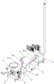
FIG. 1 is a schematic overall perspective view of the present invention;
FIG. 2 is a schematic view of a three-dimensional cutting structure of the crushing box according to the present invention;
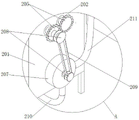
FIG. 3 is an enlarged view of FIG. 1 at A;
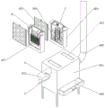
FIG. 4 is a schematic perspective view of an exhaust treatment mechanism according to the present invention;
FIG. 5 is an enlarged view of FIG. 4 at B;
FIG. 6 is an enlarged view at C of FIG. 4;
FIG. 7 is an enlarged view of FIG. 1 at D;
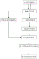
FIG. 8 is a system flow diagram of the present invention.
In the figure: 1. an incinerator body; 2. a garbage crushing pump conveying mechanism; 3. a burning oxygen supply mechanism; 4. an exhaust gas treatment mechanism; 5. a hydrogen supply pipe; 6. a flame gun; 7. an electric cabinet; 8. a PLC controller; 9. a feeding control module; 10. an incineration control module; 11. a incineration oxygen amount detection module; 12. an oxygen supply supplement module; 13. an exhaust gas combustion processing control module; 14. an exhaust gas detection and discharge module; 15. and a remote control module.
201. Putting in a crushing box; 202. a rotating shaft; 203. a crushing roller; 204. a first motor; 205. a gear; 206. vibrating the sieve plate; 207. a delivery pump; 208. a belt pulley; 209. a belt; 210. a material suction pipe; 211. a delivery pipe.
301. An electrolytic water oxygen generator; 302. an oxygen supply tube;
401. a waste gas treatment tank; 402. a flue gas discharge pipe; 403. inserting the slots; 404. installing a frame; 405. filtering the plate; 406. a settling drawer; 407. a waste heat utilization unit; 408. an activated carbon adsorption unit; 409. discharging a chimney;
4071. a spiral copper pipe; 4072. a spiral heat absorption tube; 4073. a flange;
4081. adsorbing active carbon; 4082. a stirring shaft; 4083. brushing; 4084. a second motor.
Detailed Description
The technical solutions in the embodiments of the present invention will be clearly and completely described below with reference to the drawings in the embodiments of the present invention, and it is obvious that the described embodiments are only a part of the embodiments of the present invention, and not all of the embodiments. All other embodiments, which can be derived by a person skilled in the art from the embodiments given herein without making any creative effort, shall fall within the protection scope of the present invention.
Referring to fig. 1-6, a solid waste incinerator in plateau area is shown, comprising:
an incinerator body 1 for incinerating solid waste garbage;
the garbage crushing pump conveying mechanism 2 is used for crushing solid waste garbage and conveying the solid waste garbage by a pump, and the stable garbage crushing pump conveying mechanism 2 is arranged on one side of the incinerator main body 1;
the incineration oxygen supplementing mechanism 3 is used for supplementing the incineration oxygen for the working oxygen of the incinerator in the highland oxygen thin environment, and the incineration oxygen supplementing mechanism 3 is arranged on one side of the incinerator body 1;
and an exhaust gas treatment means 4, wherein the exhaust gas treatment means 4 is mounted on the exhaust gas discharge end of the incinerator body 1.
Wherein, the garbage crushing pump conveying mechanism 2 comprises a throwing crushing box 201, a rotating shaft 202 is symmetrically and rotatably installed on the inner wall of the top of the throwing crushing box 201, a crushing roller 203 is arranged on the outer wall of the middle part of the rotating shaft 202, a first motor 204 is installed on the outer wall of one side of the throwing crushing box 201, one end of the first motor 204 is connected with one end of the rotating shaft 202, the other end of the rotating shaft 202 is connected with a gear 205, the gears 205 are connected in a meshing manner, a vibrating screen plate 206 is installed on the inner wall of the throwing crushing box 201 below the crushing roller 203, a material conveying pump 207 is installed on the outer wall of one side of the throwing crushing box 201, belt pulleys 208 are installed on the input shaft of the material conveying pump 207 and the outer wall of one end of the rotating shaft 202, a belt 209 is sleeved on the outer wall between the belt pulleys 208, the material sucking end of the material conveying pump 207 is connected with a material sucking pipe 210, and one end of the material sucking pipe 210 is connected with the inner wall of the bottom of the throwing crushing box 201 in a penetrating manner, a material conveying end of the material conveying pump 207 is connected with a material conveying pipe 211, and one end of the material conveying pipe 211 is connected with a material inlet end of the incinerator main body 1; through the setting of rubbish crushing pump mechanism 2, carry out useless bits of broken glass to the solid useless rubbish of burning and refine the preliminary treatment, the mode of rethread gang pump input will refine gu useless rubbish spout into the incinerator, can burn the solid useless rubbish of refining fast through burning the burning furnace, improved the work efficiency who burns burning furnace.
Meanwhile, the incineration oxygen supplementing mechanism 3 comprises an electrolytic water oxygen generator 301, the oxygen delivery end of the electrolytic water oxygen generator 301 is connected with an oxygen supply pipe 302, and one end of the oxygen supply pipe 302 penetrates through the inside of the incinerator body 1; through burning oxygen complementary unit 3, can carry out the supplementary injection of oxygen in the incinerator, do benefit to the incinerator and use under the plateau environment.
The waste gas treatment mechanism 4 comprises a waste gas treatment box 401, a smoke discharge pipe 402 is connected to the outer wall of one side of the waste gas treatment box 401 in a penetrating manner, the end of the smoke discharge pipe 402 is connected with the smoke discharge end of the incinerator body 1, an insertion groove 403 is distributed on the outer wall of the top end of the waste gas treatment box 401, an installation frame 404 is inserted in the insertion groove 403, filter plates 405 are inserted on the outer walls of two sides of the installation frame 404, a precipitation drawer 406 is inserted in the inner wall of the bottom of the waste gas treatment box 401, a waste heat utilization unit 407 and an active carbon adsorption unit 408 are respectively installed in the installation frame 404, and a discharge chimney 409 is installed on the outer wall of the other side of the waste gas treatment box 401 in a penetrating manner; the waste smoke discharged after the incineration of the incinerator can be filtered through the waste gas treatment mechanism 4, and the installation frame 404 structure is favorable for the assembly of various waste gas treatment structures.
Meanwhile, the waste heat utilization unit 407 comprises a spiral copper pipe 4071, the spiral copper pipe 4071 is fixed on the inner wall of the bottom of the mounting frame 404, a spiral heat absorption pipe 4072 is wound and connected on the outer wall of the spiral copper pipe 4071, and two ends of the spiral heat absorption pipe 4072 penetrate through the outside of the mounting frame 404 and are connected with a flange 4073; waste heat utilization can be carried out on the waste flue gas discharged after incineration through the arrangement of the waste heat utilization unit 407.
The activated carbon adsorption unit 408 comprises adsorption activated carbon 4081, the adsorption activated carbon 4081 is filled in the installation frame 404, a stirring shaft 4082 is rotatably installed on the inner wall of the middle part of the installation frame 404, the outer wall of a blade of the stirring shaft 4082 is connected with a sweeping brush 4083, a second motor 4084 is fixed on the outer wall of the top end of the installation frame 404, and one end of an output shaft of the second motor 4084 is connected with the top end of the stirring shaft 4082; the activated carbon adsorption unit 408 can be used for carrying out activated carbon adsorption treatment on the waste flue gas discharged after incineration.
Simultaneously, the defeated hydrogen end of electrolysis water oxygen generator 301 is connected with hydrogen supply pipe 5, installs flame gun 6 on one side inner wall of flue gas discharge pipe 402, and the one end of hydrogen supply pipe 5 is connected with flame gun 6's fuel end, through the secondary combustion who discharges waste gas on flue gas discharge pipe 402, handles the combustible gas in the waste gas, does benefit to the emission of later stage waste gas.
Referring to fig. 7 and 8, the automatic control system of the plateau solid waste incinerator in the figure comprises an electric cabinet 7, wherein the electric cabinet 7 is fixedly installed on one side of the outer wall of a throwing crushing box 201, a PLC controller 8 is arranged on the inner wall of the middle part of the electric cabinet 7, and a feeding control module 9, an incineration control module 10, an incineration oxygen amount detection module 11, an oxygen supply supplement module 12, a waste gas combustion treatment control module 13, a waste gas detection and discharge module 14 and a remote control module 15 are distributed on the outer walls of the electric cabinet 7 on two sides of the PLC controller 8; carry out the intelligent control who burns burning furnace through control system, do benefit to the remote control of later stage to each process, provide convenience for burning furnace use.
The working principle is as follows: in the plateau solid waste incinerator, an operator can put solid waste to be treated into the throwing crushing box 201, the feeding control module 9 can drive and control the first motor 204 to work, the first motor 204 drives the rotating shaft 202 to rotate, the crushing rollers 203 on two sides can relatively rotate under the matched transmission of the gear 205, the crushing rollers 203 can continuously crush the solid waste, the crushed and refined waste falls to the bottom of the crushing box through the vibrating sieve plate 206, the belt pulley 208 can be driven to rotate in the rotating process of the rotating shaft 202, the conveying pump 207 can be driven to rotate under the transmission of the belt 209, the crushed and refined waste can be sprayed into the incinerator through the conveying pipe 211 of the suction pipe 210, the incineration control module 10 controls the incinerator to burn the refined waste, and the oxygen content in the incinerator can be detected through the incineration oxygen content detection module 11 in the incinerator in the process, when the oxygen content is too low, the oxygen supply supplementing module 12 controls the electrolytic water oxygen generator 301 to work and supplement oxygen in the incinerator through the oxygen supply pipe 302, so that sufficient combustion of garbage in the incinerator is guaranteed, waste gas generated after garbage combustion is input into the waste gas treatment box 401 through the flue gas discharge pipe 402, the waste gas combustion treatment control module 13 controls waste gas treatment, hydrogen generated during the working of the electrolytic water oxygen generator 301 is input into the flame gun 6 to be combusted, secondary combustion treatment is performed on the waste gas in the flue gas discharge pipe 402, the hydrogen is clean gas, water formed after combustion can better perform precipitation treatment on the discharged waste gas, and precipitates fall into the precipitation drawer 406 to be discharged at the later stage; the arrangement of the structure that the mounting frame 404 is inserted into the exhaust gas treatment box 401 is beneficial to expanding and mounting of the exhaust gas treatment structure, for example, the arrangement of the waste heat utilization unit 407 is connected with an external water path through the flange 4073, and water enters the spiral heat absorption pipe 4072, so that waste heat utilization of water heating can be realized; through the arrangement of the activated carbon adsorption unit 408, the particles in the discharged waste gas can be adsorbed by activated carbon, and the treated waste gas (carbon dioxide) is discharged through a discharge chimney 409; this burn burning furnace through remote control module 15's setting, does benefit to the remote control of later stage to each process, provides convenience for burning furnace use.
It is noted that, herein, relational terms such as first and second, and the like may be used solely to distinguish one entity or action from another entity or action without necessarily requiring or implying any actual such relationship or order between such entities or actions. Also, the terms "comprises," "comprising," or any other variation thereof, are intended to cover a non-exclusive inclusion, such that a process, method, article, or apparatus that comprises a list of elements does not include only those elements but may include other elements not expressly listed or inherent to such process, method, article, or apparatus.
Although embodiments of the present invention have been shown and described, it will be appreciated by those skilled in the art that changes, modifications, substitutions and alterations can be made in these embodiments without departing from the principles and spirit of the invention, the scope of which is defined in the appended claims and their equivalents.
Claims (8)
1. A solid waste incinerator in plateau, characterized by that, include:
an incinerator body (1) for incinerating solid waste garbage;
the garbage crushing pump conveying mechanism (2) is used for crushing solid waste garbage and conveying the solid waste garbage by a pump, and the stable garbage crushing pump conveying mechanism (2) is arranged on one side of the incinerator main body (1);
the incineration oxygen supplementing mechanism (3) is used for supplementing the working oxygen of the incinerator in the highland oxygen lean environment, and the incineration oxygen supplementing mechanism (3) is arranged on one side of the incinerator body (1);
and the waste gas treatment mechanism (4), wherein the waste gas treatment mechanism (4) is arranged at the waste gas discharge end of the incinerator body (1).
2. The solid waste incinerator in plateau area as claimed in claim 1, wherein: garbage crushing pump mechanism (2) is including puting in crushing case (201), symmetry rotation is installed and is rotated on the top inner wall of puting in crushing case (201) axis of rotation (202), set up crushing roller (203) on the middle part outer wall of axis of rotation (202), install first motor (204) on the outer wall of puting in crushing case (201) one side, and the one end of motor (204) is connected with the one end of axis of rotation (202), the other end of axis of rotation (202) all is connected with gear (205), and the meshing is connected between gear (205), put in and install vibration sieve board (206) on the inner wall that crushing case (201) are located crushing roller (203) below, put in and install delivery pump (207) on the outer wall of crushing case (201) one side, all install belt pulley (208) on the input shaft of delivery pump (207) and the outer wall of axis of rotation (202) one end, and the cover is equipped with belt (209) on the outer wall between belt pulley (208), the material end of inhaling of delivery pump (207) is connected with inhales material pipe (210), and inhales the one end of material pipe (210) and puts in the bottom inner wall through connection who smashes case (201), the delivery end of delivery pump (207) is connected with delivery pipe (211), and the one end of delivery pipe (211) is connected with the feed end that burns burning furnace main part (1).
3. The solid waste incinerator in plateau area as claimed in claim 1, wherein: burn oxygen complementary unit (3) and include electrolytic water oxygenerator (301), the oxygen therapy end of electrolytic water oxygenerator (301) is connected with oxygen supply pipe (302), and the one end of oxygen supply pipe (302) runs through in the inside of burning furnace main part (1).
4. The solid waste incinerator in plateau area as claimed in claim 1, wherein: waste gas treatment mechanism (4) are including exhaust-gas treatment case (401), through connection has flue gas discharge pipe (402) on the outer wall of one side of exhaust-gas treatment case (401), and the tip of flue gas discharge pipe (402) is connected with the flue gas discharge end of burning furnace main part (1), cartridge groove (403) have been seted up in the distribution on the top outer wall of exhaust-gas treatment case (401), and the inside cartridge of cartridge groove (403) has installing frame (404), the cartridge has filter plate (405) on the both sides outer wall of installing frame (404), the cartridge has sediment drawer (406) on the bottom inner wall of exhaust-gas treatment case (401), waste heat utilization unit (407) and active carbon adsorption unit (408) are installed respectively to the inside of installing frame (404), it installs emission chimney (409) to link up on the outer wall of exhaust-gas treatment case (401) opposite side.
5. The plateau solid waste incinerator as claimed in claim 3, wherein: the waste heat utilization unit (407) comprises a spiral copper pipe (4071), the spiral copper pipe (4071) is fixed on the inner wall of the bottom of the installation frame (404), a spiral heat absorption pipe (4072) is wound on the outer wall of the spiral copper pipe (4071), and two ends of the spiral heat absorption pipe (4072) penetrate through the outer portion of the installation frame (404) and are connected with a flange (4073).
6. The plateau solid waste incinerator as claimed in claim 3, wherein: activated carbon adsorption unit (408) is including adsorbing activated carbon (4081), and adsorbs activated carbon (4081) and fill in the inside of installing frame (404), rotate on the middle part inner wall of installing frame (404) and install (mixing) shaft (4082), be connected with brush (4083) on the outer wall of (mixing) shaft (4082) paddle, be fixed with second motor (4084) on the top outer wall of installing frame (404), and the output shaft one end of second motor (4084) is connected with the top of (mixing) shaft (4082).
7. The solid waste incinerator in plateau area as claimed in claims 3 and 4, wherein: the hydrogen conveying end of the electrolyzed water oxygen generator (301) is connected with a hydrogen supply pipe (5), a flame gun (6) is installed on the inner wall of one side of the flue gas discharge pipe (402), and one end of the hydrogen supply pipe (5) is connected with the fuel end of the flame gun (6).
8. The utility model provides an automatic control system of plateau solid waste incinerator, its characterized in that includes electric cabinet (7), and electric cabinet (7) fixed mounting smashes case (201) outer wall one side in putting in, be provided with PLC controller (8) on the middle part inner wall of electric cabinet (7), electric cabinet (7) are located and distribute on the outer wall of PLC controller (8) both sides and are provided with material loading control module (9), burn control module (10), burn oxygen content detection module (11), oxygen suppliment supplementary module (12), waste gas combustion processing control module (13), waste gas detection emission module (14) and remote control module (15).
Priority Applications (1)
| Application Number | Priority Date | Filing Date | Title |
|---|---|---|---|
| CN202110983480.8A CN113606591A (en) | 2021-08-25 | 2021-08-25 | Automatic control system of plateau solid waste incinerator and garbage incinerator |
Applications Claiming Priority (1)
| Application Number | Priority Date | Filing Date | Title |
|---|---|---|---|
| CN202110983480.8A CN113606591A (en) | 2021-08-25 | 2021-08-25 | Automatic control system of plateau solid waste incinerator and garbage incinerator |
Publications (1)
| Publication Number | Publication Date |
|---|---|
| CN113606591A true CN113606591A (en) | 2021-11-05 |
Family
ID=78342034
Family Applications (1)
| Application Number | Title | Priority Date | Filing Date |
|---|---|---|---|
| CN202110983480.8A Pending CN113606591A (en) | 2021-08-25 | 2021-08-25 | Automatic control system of plateau solid waste incinerator and garbage incinerator |
Country Status (1)
| Country | Link |
|---|---|
| CN (1) | CN113606591A (en) |
Cited By (1)
| Publication number | Priority date | Publication date | Assignee | Title |
|---|---|---|---|---|
| CN114234211A (en) * | 2021-12-21 | 2022-03-25 | 扬州鑫科环保成套设备有限公司 | Flue gas catalytic oxidation incinerator |
Citations (6)
| Publication number | Priority date | Publication date | Assignee | Title |
|---|---|---|---|---|
| CN107366917A (en) * | 2017-08-25 | 2017-11-21 | 四川弘毅智慧知识产权运营有限公司 | A kind of energy saving and environment friendly solid waste crushes incinerator |
| CN107642783A (en) * | 2017-09-20 | 2018-01-30 | 绍兴鑫广科技有限公司 | A kind of exhaust treatment system of chemical plant incinerator |
| CN110186054A (en) * | 2019-05-30 | 2019-08-30 | 王立臣 | A kind of polyoxy three-stage waste incineration and smoke comprehensive utilize device and its application method |
| CN211316181U (en) * | 2019-12-16 | 2020-08-21 | 浙江新华新材料科技有限责任公司 | Amino resin filters salt sediment and burns purification recovery with burning furnace |
| CN212700983U (en) * | 2020-05-22 | 2021-03-16 | 江苏诺鼎机械制造有限公司 | Exhaust gas purification machine for metal heat treatment |
| CN213207856U (en) * | 2020-07-27 | 2021-05-14 | 太仓市申瓷高温新材料有限公司 | Harmless incinerator for garbage treatment |
-
2021
- 2021-08-25 CN CN202110983480.8A patent/CN113606591A/en active Pending
Patent Citations (6)
| Publication number | Priority date | Publication date | Assignee | Title |
|---|---|---|---|---|
| CN107366917A (en) * | 2017-08-25 | 2017-11-21 | 四川弘毅智慧知识产权运营有限公司 | A kind of energy saving and environment friendly solid waste crushes incinerator |
| CN107642783A (en) * | 2017-09-20 | 2018-01-30 | 绍兴鑫广科技有限公司 | A kind of exhaust treatment system of chemical plant incinerator |
| CN110186054A (en) * | 2019-05-30 | 2019-08-30 | 王立臣 | A kind of polyoxy three-stage waste incineration and smoke comprehensive utilize device and its application method |
| CN211316181U (en) * | 2019-12-16 | 2020-08-21 | 浙江新华新材料科技有限责任公司 | Amino resin filters salt sediment and burns purification recovery with burning furnace |
| CN212700983U (en) * | 2020-05-22 | 2021-03-16 | 江苏诺鼎机械制造有限公司 | Exhaust gas purification machine for metal heat treatment |
| CN213207856U (en) * | 2020-07-27 | 2021-05-14 | 太仓市申瓷高温新材料有限公司 | Harmless incinerator for garbage treatment |
Cited By (2)
| Publication number | Priority date | Publication date | Assignee | Title |
|---|---|---|---|---|
| CN114234211A (en) * | 2021-12-21 | 2022-03-25 | 扬州鑫科环保成套设备有限公司 | Flue gas catalytic oxidation incinerator |
| CN114234211B (en) * | 2021-12-21 | 2023-08-11 | 扬州鑫科环保成套设备有限公司 | Flue gas catalytic oxidation incinerator |
Similar Documents
| Publication | Publication Date | Title |
|---|---|---|
| CN205299541U (en) | Burning furnace is burnt to high efficiency for refuse treatment | |
| CN2636094Y (en) | Refuse pyrolysis treatment device | |
| CN113606591A (en) | Automatic control system of plateau solid waste incinerator and garbage incinerator | |
| CN109695880A (en) | Garbage power incinerator with purification function | |
| CN201697133U (en) | Garbage incinerator | |
| CN206958929U (en) | A kind of garbage incinerating system with flue gas depositing dust function | |
| CN215863424U (en) | Plasma vehicle-mounted mobile medical waste disposal equipment | |
| CN214536211U (en) | High-efficiency incinerator for waste incineration | |
| CN211502788U (en) | Waste plastic environmental protection incineration device for building construction | |
| CN212132464U (en) | Garbage incinerator for garbage power generation | |
| CN210219786U (en) | Urban environment refuse treatment is with burning furnace that burns | |
| KR100704166B1 (en) | An incineration system | |
| CN208074957U (en) | A kind of refuse pyrolysis gasification waste recovery systems | |
| CN2221717Y (en) | Multi-functional incinerator for medical refuse and solid waste | |
| CN215541343U (en) | Steel solid-state garbage incineration slag treatment device | |
| CN207936086U (en) | A kind of waste incineration purification system | |
| CN113105088A (en) | Municipal administration mud cyclic regeneration device | |
| CN213395331U (en) | Mechanical furnace with low emission of waste incineration | |
| CN217057542U (en) | Garbage treatment incinerator | |
| CN210398930U (en) | Energy-efficient pyrolysis incinerator | |
| CN215892368U (en) | Garbage incineration device | |
| CN216027043U (en) | Incineration type soil remediation device | |
| CN220169464U (en) | Medical waste incinerator with purification | |
| CN113819456B (en) | Combustor with purifying mechanism for combustion of thermal power plant | |
| CN219571934U (en) | Dangerous waste incineration treatment device |
Legal Events
| Date | Code | Title | Description |
|---|---|---|---|
| PB01 | Publication | ||
| PB01 | Publication | ||
| SE01 | Entry into force of request for substantive examination | ||
| SE01 | Entry into force of request for substantive examination |