CN113387134A - Feeding device of geomembrane laying system - Google Patents
Feeding device of geomembrane laying system Download PDFInfo
- Publication number
- CN113387134A CN113387134A CN202110637898.3A CN202110637898A CN113387134A CN 113387134 A CN113387134 A CN 113387134A CN 202110637898 A CN202110637898 A CN 202110637898A CN 113387134 A CN113387134 A CN 113387134A
- Authority
- CN
- China
- Prior art keywords
- feeding
- rise
- bottom frame
- charging box
- car
- Prior art date
- Legal status (The legal status is an assumption and is not a legal conclusion. Google has not performed a legal analysis and makes no representation as to the accuracy of the status listed.)
- Pending
Links
- 239000010720 hydraulic oil Substances 0.000 claims description 15
- 230000007246 mechanism Effects 0.000 claims description 15
- 238000007599 discharging Methods 0.000 claims description 10
- 239000000463 material Substances 0.000 abstract description 38
- 238000010276 construction Methods 0.000 abstract description 28
- 238000000034 method Methods 0.000 abstract description 4
- 230000008569 process Effects 0.000 abstract description 4
- 239000010410 layer Substances 0.000 description 75
- 239000004567 concrete Substances 0.000 description 2
- 238000009434 installation Methods 0.000 description 2
- 230000004048 modification Effects 0.000 description 2
- 238000012986 modification Methods 0.000 description 2
- 239000004576 sand Substances 0.000 description 2
- 230000009286 beneficial effect Effects 0.000 description 1
- 230000002457 bidirectional effect Effects 0.000 description 1
- 230000007547 defect Effects 0.000 description 1
- 238000010586 diagram Methods 0.000 description 1
- 230000000694 effects Effects 0.000 description 1
- 239000008187 granular material Substances 0.000 description 1
- 230000006872 improvement Effects 0.000 description 1
- -1 meanwhile Substances 0.000 description 1
- 239000011178 precast concrete Substances 0.000 description 1
- 239000011241 protective layer Substances 0.000 description 1
- 239000004575 stone Substances 0.000 description 1
- 230000001360 synchronised effect Effects 0.000 description 1
- 230000007306 turnover Effects 0.000 description 1
Images


Classifications
-
- B—PERFORMING OPERATIONS; TRANSPORTING
- B65—CONVEYING; PACKING; STORING; HANDLING THIN OR FILAMENTARY MATERIAL
- B65G—TRANSPORT OR STORAGE DEVICES, e.g. CONVEYORS FOR LOADING OR TIPPING, SHOP CONVEYOR SYSTEMS OR PNEUMATIC TUBE CONVEYORS
- B65G35/00—Mechanical conveyors not otherwise provided for
-
- B—PERFORMING OPERATIONS; TRANSPORTING
- B65—CONVEYING; PACKING; STORING; HANDLING THIN OR FILAMENTARY MATERIAL
- B65G—TRANSPORT OR STORAGE DEVICES, e.g. CONVEYORS FOR LOADING OR TIPPING, SHOP CONVEYOR SYSTEMS OR PNEUMATIC TUBE CONVEYORS
- B65G37/00—Combinations of mechanical conveyors of the same kind, or of different kinds, of interest apart from their application in particular machines or use in particular manufacturing processes
-
- E—FIXED CONSTRUCTIONS
- E02—HYDRAULIC ENGINEERING; FOUNDATIONS; SOIL SHIFTING
- E02B—HYDRAULIC ENGINEERING
- E02B3/00—Engineering works in connection with control or use of streams, rivers, coasts, or other marine sites; Sealings or joints for engineering works in general
- E02B3/04—Structures or apparatus for, or methods of, protecting banks, coasts, or harbours
- E02B3/12—Revetment of banks, dams, watercourses, or the like, e.g. the sea-floor
- E02B3/122—Flexible prefabricated covering elements, e.g. mats, strips
-
- E—FIXED CONSTRUCTIONS
- E02—HYDRAULIC ENGINEERING; FOUNDATIONS; SOIL SHIFTING
- E02B—HYDRAULIC ENGINEERING
- E02B3/00—Engineering works in connection with control or use of streams, rivers, coasts, or other marine sites; Sealings or joints for engineering works in general
- E02B3/16—Sealings or joints
Abstract
The invention discloses a feeding device of a geomembrane laying system, which mainly comprises: the transportation track is a double-row track; the low-layer feeding trolley is slidably arranged on the conveying track; the high-rise feeding car is arranged on the conveying track in a sliding mode, and a channel for the low-rise feeding car to pass through is arranged below the high-rise feeding car. The feeding device can reduce the human input cost of material transportation in the geomembrane laying process, improve the material transportation efficiency, shorten the construction period, accelerate the construction progress and improve the construction quality.
Description
Technical Field
The invention relates to the technical field of geomembrane laying, in particular to a feeding device of a geomembrane laying system.
Background
At present, hydraulic engineering geomembranes, and supporting layers and protective layers on and under the geomembranes are all laid by adopting a manual mode. The manual laying mode has the defects of high labor cost input, high field management difficulty, easy damage to the geomembrane by constructors and the like, influences the later-stage anti-seepage effect and has long construction period.
Disclosure of Invention
The invention mainly aims to provide a feeding device of a geomembrane laying system, which can reduce the human input cost of material transportation in the geomembrane laying process, improve the material transportation efficiency, shorten the construction period, accelerate the construction progress and improve the construction quality.
In order to achieve the above object, the present invention provides a feeding device of a geomembrane laying system, comprising:
the transportation track is a double-row track;
the low-layer feeding trolley is slidably arranged on the conveying track;
the high-rise feeding car is arranged on the conveying track in a sliding mode, and a channel for the low-rise feeding car to pass through is arranged below the high-rise feeding car.
Further, high-rise stack pallet includes:
the high-rise feeding car bottom frame is slidably arranged on the conveying track, and the channel is positioned below the high-rise feeding car bottom frame;
the high-rise feeding and charging box is characterized in that one end of the high-rise feeding and charging box is hinged to a bottom frame of a high-rise feeding car through a hinged shaft, a high-rise feeding hydraulic oil cylinder is hinged to the bottom frame of the high-rise feeding car, and the other end of the high-rise feeding hydraulic oil cylinder is hinged to one end, far away from the hinged shaft, of the high-rise feeding and charging box.
Furthermore, a high-rise feeding movable door plate is arranged at one end, hinged with the high-rise feeding car bottom frame, of the high-rise feeding charging box, the upper edge of the high-rise feeding movable door plate is hinged with the upper portion of the high-rise feeding charging box, and a door plate switch adjusting mechanism used for driving the high-rise feeding movable door plate to open or close is arranged on the high-rise feeding car bottom frame.
Furthermore, the door switch adjusting mechanism comprises a connecting block and a door switch adjusting pull rod, the connecting block is fixedly installed at the end part of the high-rise feeding movable door plate, the connecting block is bent, one end of the door switch adjusting pull rod is hinged with the connecting block, and the other end of the door switch adjusting pull rod is hinged to the bottom frame of the high-rise feeding vehicle.
Further, a high-rise feeding power system for driving the high-rise feeding car bottom frame to slide on the transportation rail is mounted on the high-rise feeding car bottom frame; the bottom frame of the high-rise feeding car is connected with a top traction winch on a gantry feeding working car of the geomembrane laying system through a pull rope.
Further, the low-rise feeding car comprises:
the lower-layer feeding car bottom frame is slidably arranged on the conveying track;
the lower layer pay-off charging box, the articulated installation on lower layer pay-off carriage underframe frame is passed through the articulated shaft to the one end of lower layer pay-off charging box, and articulated installation a lower layer pay-off hydraulic cylinder on the lower layer pay-off carriage underframe frame, the articulated one end of keeping away from the articulated shaft at lower layer pay-off charging box is installed to lower layer pay-off hydraulic cylinder's the other end.
Furthermore, a movable tray supporting frame used for placing a movable tray for loading massive materials (such as concrete precast blocks) is further arranged in the low-layer feeding and charging box, the movable tray supporting frame comprises at least two supporting rods, the supporting rods are arranged in the low-layer feeding and charging box, and the supporting rods are connected with a bottom plate of the low-layer feeding and charging box through a plurality of connecting rods.
Furthermore, one end of the low-layer feeding and charging box, which is close to the hinged shaft, is a discharging end, and a low-layer feeding movable door plate used for opening or closing the discharging end is arranged at the discharging end on the low-layer feeding and charging box.
Further, the low-rise feeding car further comprises a track dismounting device used for dismounting the transportation track, the track dismounting device comprises a track dismounting hanging frame, the track dismounting hanging frame is detachably mounted on the low-rise feeding car bottom frame, the track dismounting hanging frame extends out of one side of the low-rise feeding car bottom frame, and a track dismounting electric hoist is slidably mounted on the track dismounting hanging frame.
Further, a low-layer feeding power system for driving the low-layer feeding car bottom frame to move on the conveying track is arranged on the low-layer feeding car bottom frame; the bottom frame of the low-layer feeding car is connected with a top traction winch on a gantry feeding working car of the geomembrane laying system through a pull rope.
Compared with the prior art, the invention has the following beneficial effects:
through setting up double row transportation track, set up low-level pay-off car and high-rise pay-off car on the transportation track slidable to set up the passageway in the below of high-rise pay-off car and supply the low-level pay-off car to pass through. During material transportation during geomembrane laying construction, the material can be alternately transported on the transportation rail in a matched manner through the low-layer feeding trolley and the high-layer feeding trolley. When the high-rise feeding car hoists the materials at the gantry feeding working car, the low-rise feeding car loaded with the materials can move to the construction laying working car to transfer the materials to the construction laying working car; the gantry feeding working vehicle is returned after the low-layer feeding vehicle discharges materials, meanwhile, materials loaded by the high-layer feeding vehicle are conveyed to the construction laying working vehicle, and the operation is repeated, so that the efficiency of material conveying can be greatly improved, the construction progress is accelerated, the manual input in the material transportation process can be reduced, and the construction quality is improved.
Drawings
The accompanying drawings, which are incorporated in and constitute a part of this application, illustrate embodiments of the invention and, together with the description, serve to explain the invention and not to limit the invention. In the drawings:
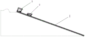
fig. 1 is a schematic structural view of a geomembrane laying system using the feeding device of the present invention.
Fig. 2 is a schematic structural diagram of the feeding device of the present invention.
Fig. 3 is a schematic perspective view of a high-rise feeding car in the feeding device of the present invention.
Fig. 4 is a schematic top view of a high-rise feed carriage in the feeding device of the present invention.
Fig. 5 is a schematic front view of a high-rise feeding car in the feeding device of the present invention.
Fig. 6 is a schematic side view of a high-rise feed carriage in the feeding device of the present invention.
Fig. 7 is a schematic perspective view of the feeding car of the lower layer of the feeding device of the present invention when the rail dismounting device is removed.
Fig. 8 is a schematic perspective view of the low-rise feeding cart of the feeding device of the present invention when the rail dismounting device is removed and the movable tray is loaded.
Fig. 9 is a schematic side view of the feeding device of the invention when the middle and lower layer feeding car is provided with the rail dismounting device and the moving tray.
Fig. 10 is a schematic perspective view of the low-rise feeding car of the feeding device of the present invention when the rail mounting/dismounting device is mounted and the movable tray is loaded.
Fig. 11 is a schematic front view of the feeding cart for the lower layer of the feeding device of the present invention when the rail mounting/dismounting device is installed and the moving tray is loaded.
Fig. 12 is a schematic top view of the low-rise feeding cart of the feeding device of the present invention when the rail mounting/dismounting device is mounted and the moving tray is loaded.
Wherein the figures include the following reference numerals:
1. a transportation track; 2. a low-level feed carriage; 3. a high-rise feeding car; 4. a channel; 21. a bottom frame of the low-layer feeding car; 22. a low-level feeding and charging box; 23. a low-layer feeding hydraulic oil cylinder; 24. moving the tray support; 25. a low-layer feeding movable door plate; 26. a rail dismounting device; 27. a low-level feeding power system; 31. a bottom frame of the high-rise feeding car; 32. a high-rise feeding and charging box; 33. a high-rise feeding hydraulic oil cylinder; 34. a high-rise feeding movable door plate; 35. a door panel switch adjustment mechanism; 36. a high-rise feeding power system; 100. a gantry feeding working vehicle; 101. a top traction winch; 110. constructing and laying a working vehicle; 120. moving the tray; 241. a support bar; 242. a connecting rod; 261. disassembling and assembling the hanger on the track; 262. the electric hoist is disassembled and assembled on the rail; 311. a vertical frame; 312. a horizontal frame; 351. connecting blocks; 352. the door plate is opened and closed to adjust the pull rod.
Detailed Description
In order to facilitate an understanding of the invention, the invention will be described more fully and in detail below with reference to the accompanying drawings and preferred embodiments, but the scope of the invention is not limited to the specific embodiments below. It should be noted that the embodiments and features of the embodiments may be combined with each other without conflict.
Unless otherwise defined, all terms of art used hereinafter have the same meaning as commonly understood by one of ordinary skill in the art. The use of "first," "second," and similar terms in the description and in the claims of the present application do not denote any order, quantity, or importance, but rather the intention is to distinguish one element from another. Also, the use of the terms "a" or "an" and the like do not denote a limitation of quantity, but rather denote the presence of at least one. The terms "connected" or "coupled" and the like are not restricted to physical or mechanical connections, but may include electrical connections, whether direct or indirect. "upper", "lower", "left", "right", and the like are used merely to indicate relative positional relationships, and when the absolute position of the object being described is changed, the relative positional relationships are changed accordingly.
Referring to fig. 1 to 12, a feeding device of a geomembrane laying system according to an embodiment of the present invention. The geomembrane laying system mainly comprises a gantry feeding work vehicle 100, a construction laying work vehicle 110 and the feeding device (see fig. 1) of the present invention. A top traction winch 101 is arranged on the top of the gantry feeding working vehicle 100. When the geomembrane laying system works, the gantry feeding working vehicle 100 hoists laying materials on the material transport vehicle to the feeding device of the invention, and the feeding device conveys the laying materials to the construction laying working vehicle 110 for laying construction.
As can be seen from the figure, the feeding device mainly comprises a transportation rail 1, a low-rise feeding car 2 and a high-rise feeding car 3. The conveying track 1 is a double-row track which can allow two feeding carts to pass through in a bidirectional and simultaneous manner, a gantry feeding working cart 100 in the geomembrane laying system is arranged at one end of the conveying track 1, and a construction laying working cart 110 is slidably arranged on the conveying track 1; the low-layer feeding car 2 can be arranged on the conveying track 1 in a sliding manner; the high-rise feeding car 3 is also arranged on the transportation track 1 in a sliding way, and a channel 4 for the low-rise feeding car 2 to pass through is arranged below the high-rise feeding car 3.
The feeding device of the geomembrane laying system is provided with the conveying track 1 capable of passing through in two directions, the conveying track 1 is slidably provided with the low-layer feeding trolley 2 and the high-layer feeding trolley 3, and the passage 4 is arranged below the high-layer feeding trolley 3 and is used for the low-layer feeding trolley 2 to pass through. In the working hours of the geomembrane laying facility, erecting a transportation rail 1 above a working surface to be laid, arranging a gantry feeding working vehicle 100 at one end of the transportation rail 1, and slidably installing a low-layer feeding vehicle 2, a high-layer feeding vehicle 3 and a construction laying working vehicle 110 on the transportation rail 1; the paving materials (such as sand, broken stone, concrete prefabricated blocks and the like) on the material transport vehicle are hoisted to the low-layer feed carriage 2 and the high-layer feed carriage 3 through the gantry feeding work vehicle 100, and the paving materials are conveyed to the construction paving work vehicle 110 through the low-layer feed carriage 2 and the high-layer feed carriage 3 for paving construction. The transportation track 1 adopts a double-row track, and a channel 4 for the low-layer feeding trolley 2 to pass through is arranged below the high-layer feeding trolley 3; in the material transportation process, the materials can be alternately transported on the transportation track in a matched manner through the low-layer feeding car 2 and the high-layer feeding car 3. When the high-rise feeding car 3 hoists materials at the gantry feeding working car 100, the low-rise feeding car 2 loaded with the materials can move to the construction and laying working car 110 to transfer the materials to the construction and laying working car 110; when the low-layer feeding car 2 finishes discharging, the materials return to the gantry feeding working car 100, and meanwhile, the materials loaded by the high-layer feeding car 3 are conveyed to the construction laying working car 110, so that the materials are repeatedly conveyed, the efficiency of material conveying can be greatly improved, and the construction progress is accelerated.
Specifically, referring to fig. 3 to 6, in the present embodiment, the high-rise feed carriage 3 mainly includes a high-rise feed carriage bottom frame 31 and a high-rise feed charging box 32. The high-rise feeding car bottom frame 31 is slidably arranged on the conveying track 1, and the channel 4 is positioned below the high-rise feeding car bottom frame 31; one end of the high-rise feeding and charging box 32 is hinged and installed on the bottom frame 31 of the high-rise feeding car through a hinge shaft, a high-rise feeding hydraulic oil cylinder 33 is further hinged and installed on the bottom frame 31 of the high-rise feeding car, and the other end of the high-rise feeding hydraulic oil cylinder 33 is hinged and installed at one end, far away from the hinge shaft, of the high-rise feeding and charging box 32. By the arrangement, when unloading is needed, the high-rise feeding hydraulic oil cylinder 33 extends out, one end, far away from the hinge shaft, of the high-rise feeding charging box 32 is lifted, the high-rise feeding charging box 32 can be turned over, paving materials in the high-rise feeding charging box 32 are transferred into the construction and paving work car 110, and operation is very convenient.
Referring to fig. 3 to 6, in this embodiment, a high-rise feeding movable door panel 34 is further disposed at one end of the high-rise feeding charging box 32 hinged to the high-rise feeding car bottom frame 31, an upper edge of the high-rise feeding movable door panel 34 is hinged to an upper portion of the high-rise feeding charging box 32, and a door panel opening and closing adjusting mechanism 35 is further disposed on the high-rise feeding car bottom frame 31, and the door panel opening and closing adjusting mechanism 35 is used for driving the high-rise feeding movable door panel 34 to open or close. When the high-rise feeding and charging box 32 is lifted upwards and turned over, the door panel switch adjusting mechanism 35 drives the high-rise feeding movable door panel 34 to be opened, and paving materials are discharged from the high-rise feeding movable door panel 34 into the construction and paving work vehicle 110; after the unloading is finished, the high-rise feeding hydraulic oil cylinder 33 retracts, the high-rise feeding charging box 32 returns downwards, and meanwhile, the door plate switch adjusting mechanism 35 drives the high-rise feeding movable door plate 34 to close. Through reasonable matching between the door plate switch adjusting mechanism 35 and the high-rise feeding movable door plate 34, the high-rise feeding and charging box 32 is lifted and opened synchronously with the high-rise feeding movable door plate 34, and the high-rise feeding and charging box 32 is descended and closed synchronously with the high-rise feeding movable door plate 34.
Specifically, the door switch adjusting mechanism 35 includes a connecting block 351 and a door switch adjusting pull rod 352, the connecting block 351 is fixedly mounted at the end of the high-rise feeding movable door plate 34, the connecting block 351 is bent, one end of the door switch adjusting pull rod 352 is hinged to the connecting block 351, and the other end of the door switch adjusting pull rod 352 is hinged to the high-rise feeding car bottom frame 31. With the arrangement, when the high-rise feeding and charging box 32 is lifted upwards and turned over, the door panel switch adjusting pull rod 352 pulls the connecting block 351, so that the lower end of the high-rise feeding movable door panel 34 is driven to turn over upwards, and the high-rise feeding movable door panel 34 is opened to discharge. When the high-rise feeding and charging box 32 returns downwards, the door panel switch adjusting pull rod 352 pulls the connecting block 351, so that the lower end of the high-rise feeding movable door panel 34 is driven to return, and the high-rise feeding movable door panel 34 is closed. In this way, the door opening and closing adjustment mechanism 35 need not be powered and can be synchronized with the turning and returning of the high-rise feed and fill box 32.
Further, referring to fig. 3 to 5, the door opening/closing adjusting mechanism 35 is disposed on both ends of the high-rise movable door panel 34 on the bottom frame 31 of the high-rise feeding carriage. When the high-rise feeding movable door panel 34 is opened or closed, the door panel switch adjusting mechanisms 35 at the two ends simultaneously act, and the high-rise feeding movable door panel 34 is driven to rotate from the two ends of the high-rise feeding movable door panel 34, so that the stability of the high-rise feeding movable door panel 34 during overturning can be improved.
Specifically, referring to fig. 3, 5 and 6, in the present embodiment, the high-rise feeder carriage bottom frame 31 specifically includes two vertical frames 311 and one horizontal frame 312, the horizontal frame 312 is mounted on top of the two vertical frames 311, the vertical frame 311 and the horizontal frame 312 jointly enclose the channel 4, and the overhead height of the horizontal frame 312 (i.e. the height of the channel 4) is greater than the height of the low-rise feeder carriage 2. So set up, can ensure that low level pay-off car 2 can follow passageway 4 below horizontal frame 312 and pass through, make high-rise pay-off car 3 and low level pay-off car 2 can alternate cooperation transportation material on transportation track 1.
In this embodiment, a high-rise feeding power system 36 is further installed on the high-rise feeding car bottom frame 31, and the high-rise feeding power system 36 is used for driving the high-rise feeding car bottom frame 31 to slide on the transportation rail 1 and providing power for the high-rise feeding car 3 to move on the transportation rail 1. Further, the bottom frame 31 of the high-rise feeding car is connected with a top traction winch 101 on a gantry feeding work vehicle 100 of the geomembrane laying system through a pull rope (not shown in the figure). The high-rise feed carriage 3 can be pulled to move on the transport rail 1 by the top traction winch 101. Specifically, when the transportation track 1 is erected on an inclined plane, the high-rise feeding car 3 running on the inclined transportation track 1 adopts a winch and a motor (a high-rise feeding power system 36) carried by the winch to provide power together; when the transportation track 1 is erected on a plane, the motor carried by the high-rise feeding car 3 can provide power.
Specifically, referring to fig. 7 to 12, in the present embodiment, the lower layer feeder carriage 2 mainly includes a lower layer feeder carriage base frame 21 and a lower layer feed charging box 22. Wherein, the bottom frame 21 of the low-layer feeding car is slidably arranged on the transportation track 1; one end of the low-layer feeding charging box 22 is hinged to the bottom frame 21 of the low-layer feeding car through a hinge shaft, a low-layer feeding hydraulic oil cylinder 23 is hinged to the bottom frame 21 of the low-layer feeding car, and the other end of the low-layer feeding hydraulic oil cylinder 23 is hinged to one end, far away from the hinge shaft, of the low-layer feeding charging box 22. So set up, when transferring the material in low level pay-off charging box 22 to construction laying work car 110, only need to make low level pay-off hydraulic cylinder 23 stretch out, with low level pay-off charging box 22 upwards lift the upset, can unload, unload and accomplish back low level pay-off hydraulic cylinder 23 withdrawal, low level pay-off charging box 22 return, it is very convenient to operate. This low-level stack pallet 2 slidable mounting is on the inboard track of double row transportation track 1, and high-level stack pallet 3 slides and sets up on the outside track, and low-level stack pallet 2 can be followed the passageway 4 of high-level stack pallet 3 below and passed through.
Referring to fig. 7, 8 and 10, in the present embodiment, a movable tray support 24 is further provided in the lower layer feeding and charging box 22, the movable tray support 24 is used for placing a movable tray 120, and the movable tray 120 is used for loading block-shaped materials (such as precast concrete blocks). Specifically, the movable tray support frame 24 includes at least two support rods 241, the support rods 241 are disposed in the lower layer feeding and charging box 22, and the support rods 241 are connected to the bottom plate of the lower layer feeding and charging box 22 through a plurality of connecting rods 242. With the arrangement, fine granular materials (such as sand and gravel) can be loaded below the supporting rod 241 in the low-level feeding and charging box 22, and the movable tray 120 loaded with block-shaped materials can be placed on the supporting rod 241, so that multiple materials can be transported simultaneously.
Referring to fig. 7, in the present embodiment, one end of the lower feed charging box 22 near the hinge shaft is a discharging end, and a lower feed movable door panel 25 is further provided on the lower feed charging box 22 at the discharging end, and the lower feed movable door panel 25 is openable or closable for opening or closing the discharging end of the lower feed charging box 22. When the low-layer feeding car 2 unloads, the low-layer feeding charging box 22 is lifted upwards and turned over through the low-layer feeding hydraulic oil cylinder 23, and meanwhile, the low-layer feeding movable door plate 25 is opened for unloading. The opening and closing of the low-layer feeding movable door plate 25 can be controlled by adopting a structure similar to the door plate opening and closing adjusting mechanism 35 on the high-layer feeding car 3.
Referring to fig. 9 to 12, in the present embodiment, the low-level feeding carriage 2 further includes a rail mounting and dismounting device 26, and the rail mounting and dismounting device 26 is detachably mounted on the low-level feeding carriage bottom frame 21 for mounting and dismounting the transportation rail 1. Specifically, the rail mounting and dismounting device 26 includes a rail mounting and dismounting hanger 261, the rail mounting and dismounting hanger 261 is detachably mounted on the lower layer feeder frame 21 by bolts, and the rail mounting and dismounting hanger 261 protrudes from one side of the lower layer feeder frame 21; a rail mounting and dismounting electric block 262 is slidably mounted on the rail mounting and dismounting hanger 261, and the rail mounting and dismounting hanger 261 is disposed in a direction perpendicular to the transportation rail 1. When the low-layer feeding car 2 is used for transporting materials, the rail dismounting device 26 is dismounted from the bottom frame 21 of the low-layer feeding car, and the low-layer feeding car 2 can be matched with the high-layer feeding car 3 to transport the materials through the channel 4 at the lower part of the high-layer feeding car 3; after one is waited to lay the working face construction and is accomplished, need shift to next working face and spread the facility man-hour, can install this track dismouting device 26 on low-rise feed carriage underframe frame 21, through this track dismouting device 26 with the transportation track 1 hoist after dismantling to next working face department and reassemble. Thus, the efficiency of attaching and detaching the transportation rail 1 can be improved.
Similarly to the high-rise feeding car 3, in the present embodiment, a low-rise feeding power system 27 is also arranged on the low-rise feeding car bottom frame 21, and the low-rise feeding power system 27 is used for driving the low-rise feeding car bottom frame 21 to move on the transportation rail 1 and providing power for the low-rise feeding car 2 to move on the transportation rail 1. Further, the lower layer feeding car bottom frame 21 is connected with a top traction winch 101 on a gantry feeding work vehicle 100 of the geomembrane laying system through a pull rope (not shown in the figure). The lower layer feed carriage 2 may be pulled by a top traction winch 101 to move on the transport track 1. Specifically, when the transportation track 1 is erected on an inclined plane, the low-level feeding car 2 running on the inclined transportation track 1 adopts a winch and a motor (a low-level feeding power system 27) carried by the winch to provide power together; when the transportation track 1 is erected on a plane, the motor carried by the low-level feeding car 2 can provide power.
The above description is only a preferred embodiment of the present invention and is not intended to limit the present invention, and various modifications and changes may be made by those skilled in the art. Any modification, equivalent replacement, or improvement made within the spirit and principle of the present invention should be included in the protection scope of the present invention.
Claims (10)
1. A feeding device of a geomembrane laying system, comprising:
a transport track (1), the transport track (1) being a double-row track;
the low-layer feeding car (2) is slidably arranged on the conveying track (1);
the high-rise feeding car (3) is slidably arranged on the conveying track (1), and a channel (4) for the low-rise feeding car (2) to pass through is arranged below the high-rise feeding car (3).
2. Feeding device of a geomembrane laying system according to claim 1, characterized in that said high-rise feeding carriage (3) comprises:
the high-rise feeding car bottom frame (31) is slidably arranged on the conveying track (1), and the channel (4) is positioned below the high-rise feeding car bottom frame (31);
the high-rise feeding and charging box (32) is characterized in that one end of the high-rise feeding and charging box (32) is hinged to the high-rise feeding car bottom frame (31) through a hinge shaft, a high-rise feeding hydraulic oil cylinder (33) is hinged to the high-rise feeding car bottom frame (31), and the other end of the high-rise feeding hydraulic oil cylinder (33) is hinged to one end, far away from the hinge shaft, of the high-rise feeding and charging box (32).
3. The feeding device of the geomembrane laying system according to claim 2, wherein a high-rise feeding movable door plate (34) is arranged at one end of the high-rise feeding charging box (32) hinged with the high-rise feeding car bottom frame (31), the upper edge of the high-rise feeding movable door plate (34) is hinged with the upper part of the high-rise feeding charging box (32), and a door plate opening and closing adjusting mechanism (35) for driving the high-rise feeding movable door plate (34) to open or close is arranged on the high-rise feeding car bottom frame (31).
4. The feeding device of the geomembrane laying system according to claim 3, wherein the door plate opening and closing adjusting mechanism (35) comprises a connecting block (351) and a door plate opening and closing adjusting pull rod (352), the connecting block (351) is fixedly installed at the end of the high-rise feeding movable door plate (34), the connecting block (351) is bent, one end of the door plate opening and closing adjusting pull rod (352) is hinged with the connecting block (351), and the other end of the door plate opening and closing adjusting pull rod (352) is hinged on the high-rise feeding car bottom frame (31).
5. The feeding device of the geomembrane laying system according to claim 2, wherein a high-rise feeding power system (36) for driving the high-rise feeding car bottom frame (31) to slide on the transportation rail (1) is installed on the high-rise feeding car bottom frame (31); the high-rise feeding car bottom frame (31) is connected with a top traction winch (101) on a gantry feeding working car (100) of the geomembrane laying system through a pull rope.
6. Feeding device of a geomembrane laying system according to any one of claims 1 to 5, characterized in that said low layer feed carriage (2) comprises:
the low-layer feeding car bottom frame (21) is slidably arranged on the conveying track (1);
the lower-layer feeding and charging box (22) is hinged to one end of the lower-layer feeding and charging box (22) through a hinged shaft and mounted on a lower-layer feeding car bottom frame (21), a lower-layer feeding hydraulic oil cylinder (23) is hinged to the lower-layer feeding car bottom frame (21), and the other end of the lower-layer feeding hydraulic oil cylinder (23) is hinged to one end, far away from the hinged shaft, of the lower-layer feeding and charging box (22).
7. The feeding device of the geomembrane laying system according to claim 6, wherein a moving tray support frame (24) for placing a moving tray (120) is further provided in the lower layer feeding and charging box (22), the moving tray support frame (24) comprises at least two support rods (241), the support rods (241) are provided in the lower layer feeding and charging box (22), and the support rods (241) are connected with the bottom plate of the lower layer feeding and charging box (22) through a plurality of connecting rods (242).
8. Feeding device for geomembrane laying systems according to claim 6, wherein an end of said lower layer feeding and charging box (22) adjacent to said hinge axis is a discharging end, and a lower layer feeding movable door panel (25) for opening or closing said discharging end is provided on said lower layer feeding and charging box (22) at said discharging end.
9. The feeding device of the geomembrane laying system according to claim 6, wherein said lower layer feeding car (2) further comprises a rail mounting and dismounting device (26) for mounting and dismounting said transporting rail (1), said rail mounting and dismounting device (26) comprises a rail mounting and dismounting hanger (261), said rail mounting and dismounting hanger (261) is detachably mounted on said lower layer feeding car bottom frame (21), said rail mounting and dismounting hanger (261) extends from one side of said lower layer feeding car bottom frame (21), and a rail mounting and dismounting electric hoist (262) is slidably mounted on said rail mounting and dismounting hanger (261).
10. The feeding device of the geomembrane laying system according to claim 6, wherein a low layer feeding power system (27) for driving the low layer feeding car bottom frame (21) to move on the transportation rail (1) is arranged on the low layer feeding car bottom frame (21); the lower layer feeding car bottom frame (21) is connected with a top traction winch (101) on a gantry feeding working car (100) of the geomembrane laying system through a pull rope.
Priority Applications (1)
| Application Number | Priority Date | Filing Date | Title |
|---|---|---|---|
| CN202110637898.3A CN113387134A (en) | 2021-06-08 | 2021-06-08 | Feeding device of geomembrane laying system |
Applications Claiming Priority (1)
| Application Number | Priority Date | Filing Date | Title |
|---|---|---|---|
| CN202110637898.3A CN113387134A (en) | 2021-06-08 | 2021-06-08 | Feeding device of geomembrane laying system |
Publications (1)
| Publication Number | Publication Date |
|---|---|
| CN113387134A true CN113387134A (en) | 2021-09-14 |
Family
ID=77618476
Family Applications (1)
| Application Number | Title | Priority Date | Filing Date |
|---|---|---|---|
| CN202110637898.3A Pending CN113387134A (en) | 2021-06-08 | 2021-06-08 | Feeding device of geomembrane laying system |
Country Status (1)
| Country | Link |
|---|---|
| CN (1) | CN113387134A (en) |
Citations (42)
| Publication number | Priority date | Publication date | Assignee | Title |
|---|---|---|---|---|
| CN101676187A (en) * | 2008-09-18 | 2010-03-24 | 株式会社日立建筑系统 | Method for reconstruction of passenger conveyer |
| CN202016465U (en) * | 2011-01-18 | 2011-10-26 | 王银虎 | Rock coal storing and transferring vehicle |
| CN102311042A (en) * | 2010-06-29 | 2012-01-11 | 沈阳铝镁设计研究院有限公司 | Lifting appliance of transport system for intensive overhaul of electrolytic bath and lifting method |
| CN102847885A (en) * | 2012-09-20 | 2013-01-02 | 孟昭贵 | Horizontal mould parting static pressure molding machine and static pressure molding machine set capable of achieving automatic mould assembly |
| CN103434853A (en) * | 2013-09-10 | 2013-12-11 | 天津市华茂科技有限公司 | Pre-high speed unstacking device for automobile frame punching line |
| CN203767500U (en) * | 2014-02-17 | 2014-08-13 | 珠海市粤华园林绿化建设管理有限公司 | Slope feeding system |
| CN104670838A (en) * | 2014-12-26 | 2015-06-03 | 中国煤炭科工集团太原研究院有限公司 | Open-pit mine belt conveyor head segment transverse moving device |
| CN105292980A (en) * | 2015-10-30 | 2016-02-03 | 中汽昌兴(洛阳)机电设备工程有限公司 | Conveying system and hoisting tools and conveying device of conveying system |
| EP3009457A1 (en) * | 2014-10-14 | 2016-04-20 | Abu Dhabi Polymers Co. Ltd (Borouge) LLC. | Geomembrane applications based on polyethylene |
| CN205602593U (en) * | 2016-04-29 | 2016-09-28 | 西继迅达(许昌)电梯有限公司 | Steel sheet material feeding unit |
| CN205975476U (en) * | 2016-08-29 | 2017-02-22 | 中国水利水电第八工程局有限公司 | Domatic construction material transfer device |
| CN206481557U (en) * | 2017-01-18 | 2017-09-08 | 罗伊力尔(苏州)智能科技有限公司 | Feeding of chip mounter device |
| CN206778969U (en) * | 2017-02-28 | 2017-12-22 | 苏州卓创工业机器人自动化有限公司 | A kind of cylindrical battery testing, sorting device |
| CN107651457A (en) * | 2017-09-27 | 2018-02-02 | 徐州市申克测控机电设备有限公司 | A kind of intelligently scum soil discharge system and discharging method |
| CN207242936U (en) * | 2017-10-13 | 2018-04-17 | 浙江金麦特自动化系统有限公司 | A kind of material bending preprocessing system |
| CN207404758U (en) * | 2017-10-09 | 2018-05-25 | 中铁二十一局集团第五工程有限公司 | A kind of small-sized gantry crane replaced track plates or take off plate |
| CN207498754U (en) * | 2017-10-26 | 2018-06-15 | 中铁上海工程局集团有限公司 | A kind of novel track-laying machine of city track traffic engineering |
| CN207618622U (en) * | 2017-12-19 | 2018-07-17 | 安徽省华夏机床制造有限公司 | A kind of frame-type plate conveying equipment |
| CN108590745A (en) * | 2018-04-03 | 2018-09-28 | 上海隧道工程有限公司 | The transportation resources of shield method tunnel construction and its transport structure |
| CN109178827A (en) * | 2018-08-23 | 2019-01-11 | 宋建军 | A kind of door of elevator production feeding and conveying device |
| US20190085522A1 (en) * | 2016-01-26 | 2019-03-21 | Carpi Tech B.V. | Method and device for the laying down of a geomembrane |
| CN209011090U (en) * | 2018-08-20 | 2019-06-21 | 云南省红河州水利水电勘察设计研究院 | A kind of hydraulic engineering irrigates, flood control dam |
| CN110409262A (en) * | 2019-08-05 | 2019-11-05 | 张鸿杰 | A kind of automatic tile work equipment in municipal administration road face |
| CN110712941A (en) * | 2019-11-13 | 2020-01-21 | 红河哈尼族彝族自治州水利水电工程地质勘察咨询规划研究院 | Rail set among automatic sanding device of hydraulic engineering |
| CN110722940A (en) * | 2019-09-20 | 2020-01-24 | 中铁上海工程局集团有限公司 | Highway-railway dual-purpose bidirectional driving traction and cargo carrying transport vehicle and use method thereof |
| CN110733847A (en) * | 2019-11-13 | 2020-01-31 | 红河哈尼族彝族自治州水利水电工程地质勘察咨询规划研究院 | automatic sand paving device on hydraulic engineering inclined plane |
| CN110770400A (en) * | 2017-05-30 | 2020-02-07 | 洛桑联邦理工学院 | Geotextile |
| CN111074893A (en) * | 2019-12-25 | 2020-04-28 | 红河哈尼族彝族自治州水利水电工程地质勘察咨询规划研究院 | Construction system and construction method of concrete cushion layer of river levee dam |
| CN210558971U (en) * | 2019-06-28 | 2020-05-19 | 中隧隧盾国际建设工程有限公司 | Transport vehicle for dismantling shield construction track |
| CN210763087U (en) * | 2019-10-30 | 2020-06-16 | 常州市盈天自动化科技有限公司 | Feeding and discharging conveying device for high and low positions of plate |
| CN111532287A (en) * | 2020-05-19 | 2020-08-14 | 福建农林大学 | Orchard conveying device with detachable guide rails and orchard conveying method |
| CN211547186U (en) * | 2019-12-10 | 2020-09-22 | 河南省大道路业有限公司 | Continuous micro-surfacing paver |
| CN211645797U (en) * | 2019-10-21 | 2020-10-09 | 中铁第五勘察设计院集团有限公司 | Urban rail transit complete construction equipment |
| CN111891675A (en) * | 2020-07-27 | 2020-11-06 | 中国一冶集团有限公司 | Autoloader for building site |
| CN111891775A (en) * | 2020-08-25 | 2020-11-06 | 山东固润工程技术有限公司 | Intelligent loading hopper and material transferring method |
| CN111963220A (en) * | 2020-08-31 | 2020-11-20 | 中铁六局集团有限公司 | Tunnel trackless transportation construction system |
| CN212150439U (en) * | 2020-05-25 | 2020-12-15 | 唐山贵友机械制造有限公司 | Bidirectional conveying heavy plate feeder |
| CN112124987A (en) * | 2020-09-07 | 2020-12-25 | 苗林展 | Container transportation loading and unloading system and method |
| CN112160290A (en) * | 2020-10-14 | 2021-01-01 | 浙江世润建创科技发展有限公司 | Construction device and construction method for cast-in-place concrete panel of upstream slope of dam |
| CN212404667U (en) * | 2020-01-19 | 2021-01-26 | 中交二公局第三工程有限公司 | Device is demolishd to track subassembly in shield structure TBM tunnel |
| CN112359779A (en) * | 2020-11-10 | 2021-02-12 | 中国长江电力股份有限公司 | Inclined concrete turnover construction integrated device and construction process thereof |
| CN212612285U (en) * | 2020-07-20 | 2021-02-26 | 河南水建集团有限公司 | Concrete paving device for canal lining |
-
2021
- 2021-06-08 CN CN202110637898.3A patent/CN113387134A/en active Pending
Patent Citations (42)
| Publication number | Priority date | Publication date | Assignee | Title |
|---|---|---|---|---|
| CN101676187A (en) * | 2008-09-18 | 2010-03-24 | 株式会社日立建筑系统 | Method for reconstruction of passenger conveyer |
| CN102311042A (en) * | 2010-06-29 | 2012-01-11 | 沈阳铝镁设计研究院有限公司 | Lifting appliance of transport system for intensive overhaul of electrolytic bath and lifting method |
| CN202016465U (en) * | 2011-01-18 | 2011-10-26 | 王银虎 | Rock coal storing and transferring vehicle |
| CN102847885A (en) * | 2012-09-20 | 2013-01-02 | 孟昭贵 | Horizontal mould parting static pressure molding machine and static pressure molding machine set capable of achieving automatic mould assembly |
| CN103434853A (en) * | 2013-09-10 | 2013-12-11 | 天津市华茂科技有限公司 | Pre-high speed unstacking device for automobile frame punching line |
| CN203767500U (en) * | 2014-02-17 | 2014-08-13 | 珠海市粤华园林绿化建设管理有限公司 | Slope feeding system |
| EP3009457A1 (en) * | 2014-10-14 | 2016-04-20 | Abu Dhabi Polymers Co. Ltd (Borouge) LLC. | Geomembrane applications based on polyethylene |
| CN104670838A (en) * | 2014-12-26 | 2015-06-03 | 中国煤炭科工集团太原研究院有限公司 | Open-pit mine belt conveyor head segment transverse moving device |
| CN105292980A (en) * | 2015-10-30 | 2016-02-03 | 中汽昌兴(洛阳)机电设备工程有限公司 | Conveying system and hoisting tools and conveying device of conveying system |
| US20190085522A1 (en) * | 2016-01-26 | 2019-03-21 | Carpi Tech B.V. | Method and device for the laying down of a geomembrane |
| CN205602593U (en) * | 2016-04-29 | 2016-09-28 | 西继迅达(许昌)电梯有限公司 | Steel sheet material feeding unit |
| CN205975476U (en) * | 2016-08-29 | 2017-02-22 | 中国水利水电第八工程局有限公司 | Domatic construction material transfer device |
| CN206481557U (en) * | 2017-01-18 | 2017-09-08 | 罗伊力尔(苏州)智能科技有限公司 | Feeding of chip mounter device |
| CN206778969U (en) * | 2017-02-28 | 2017-12-22 | 苏州卓创工业机器人自动化有限公司 | A kind of cylindrical battery testing, sorting device |
| CN110770400A (en) * | 2017-05-30 | 2020-02-07 | 洛桑联邦理工学院 | Geotextile |
| CN107651457A (en) * | 2017-09-27 | 2018-02-02 | 徐州市申克测控机电设备有限公司 | A kind of intelligently scum soil discharge system and discharging method |
| CN207404758U (en) * | 2017-10-09 | 2018-05-25 | 中铁二十一局集团第五工程有限公司 | A kind of small-sized gantry crane replaced track plates or take off plate |
| CN207242936U (en) * | 2017-10-13 | 2018-04-17 | 浙江金麦特自动化系统有限公司 | A kind of material bending preprocessing system |
| CN207498754U (en) * | 2017-10-26 | 2018-06-15 | 中铁上海工程局集团有限公司 | A kind of novel track-laying machine of city track traffic engineering |
| CN207618622U (en) * | 2017-12-19 | 2018-07-17 | 安徽省华夏机床制造有限公司 | A kind of frame-type plate conveying equipment |
| CN108590745A (en) * | 2018-04-03 | 2018-09-28 | 上海隧道工程有限公司 | The transportation resources of shield method tunnel construction and its transport structure |
| CN209011090U (en) * | 2018-08-20 | 2019-06-21 | 云南省红河州水利水电勘察设计研究院 | A kind of hydraulic engineering irrigates, flood control dam |
| CN109178827A (en) * | 2018-08-23 | 2019-01-11 | 宋建军 | A kind of door of elevator production feeding and conveying device |
| CN210558971U (en) * | 2019-06-28 | 2020-05-19 | 中隧隧盾国际建设工程有限公司 | Transport vehicle for dismantling shield construction track |
| CN110409262A (en) * | 2019-08-05 | 2019-11-05 | 张鸿杰 | A kind of automatic tile work equipment in municipal administration road face |
| CN110722940A (en) * | 2019-09-20 | 2020-01-24 | 中铁上海工程局集团有限公司 | Highway-railway dual-purpose bidirectional driving traction and cargo carrying transport vehicle and use method thereof |
| CN211645797U (en) * | 2019-10-21 | 2020-10-09 | 中铁第五勘察设计院集团有限公司 | Urban rail transit complete construction equipment |
| CN210763087U (en) * | 2019-10-30 | 2020-06-16 | 常州市盈天自动化科技有限公司 | Feeding and discharging conveying device for high and low positions of plate |
| CN110733847A (en) * | 2019-11-13 | 2020-01-31 | 红河哈尼族彝族自治州水利水电工程地质勘察咨询规划研究院 | automatic sand paving device on hydraulic engineering inclined plane |
| CN110712941A (en) * | 2019-11-13 | 2020-01-21 | 红河哈尼族彝族自治州水利水电工程地质勘察咨询规划研究院 | Rail set among automatic sanding device of hydraulic engineering |
| CN211547186U (en) * | 2019-12-10 | 2020-09-22 | 河南省大道路业有限公司 | Continuous micro-surfacing paver |
| CN111074893A (en) * | 2019-12-25 | 2020-04-28 | 红河哈尼族彝族自治州水利水电工程地质勘察咨询规划研究院 | Construction system and construction method of concrete cushion layer of river levee dam |
| CN212404667U (en) * | 2020-01-19 | 2021-01-26 | 中交二公局第三工程有限公司 | Device is demolishd to track subassembly in shield structure TBM tunnel |
| CN111532287A (en) * | 2020-05-19 | 2020-08-14 | 福建农林大学 | Orchard conveying device with detachable guide rails and orchard conveying method |
| CN212150439U (en) * | 2020-05-25 | 2020-12-15 | 唐山贵友机械制造有限公司 | Bidirectional conveying heavy plate feeder |
| CN212612285U (en) * | 2020-07-20 | 2021-02-26 | 河南水建集团有限公司 | Concrete paving device for canal lining |
| CN111891675A (en) * | 2020-07-27 | 2020-11-06 | 中国一冶集团有限公司 | Autoloader for building site |
| CN111891775A (en) * | 2020-08-25 | 2020-11-06 | 山东固润工程技术有限公司 | Intelligent loading hopper and material transferring method |
| CN111963220A (en) * | 2020-08-31 | 2020-11-20 | 中铁六局集团有限公司 | Tunnel trackless transportation construction system |
| CN112124987A (en) * | 2020-09-07 | 2020-12-25 | 苗林展 | Container transportation loading and unloading system and method |
| CN112160290A (en) * | 2020-10-14 | 2021-01-01 | 浙江世润建创科技发展有限公司 | Construction device and construction method for cast-in-place concrete panel of upstream slope of dam |
| CN112359779A (en) * | 2020-11-10 | 2021-02-12 | 中国长江电力股份有限公司 | Inclined concrete turnover construction integrated device and construction process thereof |
Non-Patent Citations (1)
| Title |
|---|
| 基建不倒翁: "这款充满未来感公交车!堵车时能自动伸缩轮子,不用担心堵车问题", Retrieved from the Internet <URL:https://baijiahao.baidu.com/s?id=1644844656488406507> * |
Similar Documents
| Publication | Publication Date | Title |
|---|---|---|
| US11772688B2 (en) | Mobile crane systems and methods | |
| KR102450934B1 (en) | mortar mixing equipment for precast concrete track slab construction | |
| CN109968516B (en) | Comprehensive production system and production method for PC (polycarbonate) components | |
| CN110653945A (en) | Compact modularization concrete mixing equipment | |
| CN113387134A (en) | Feeding device of geomembrane laying system | |
| US20070297883A1 (en) | Bulk material unloading system and method | |
| CN215158473U (en) | Low-layer feeding and track dismounting vehicle of geomembrane laying system | |
| CN215158472U (en) | High-rise feeding car of geomembrane laying system | |
| CN112356259B (en) | High-strength high-performance concrete pipe pile automatic production line | |
| CN217267251U (en) | Geomembrane laying system | |
| CN211197640U (en) | Road construction bank protection material conveyor | |
| CN112960317A (en) | Garbage transfer system and operation method thereof | |
| CN113293736A (en) | Geomembrane laying system and method | |
| CN106516571A (en) | Long-distance cableway transport method | |
| CN112623783A (en) | Movable mixing pot in-situ overturning discharging device and operation method thereof | |
| CN111216250A (en) | Stabilized soil mixing plant | |
| CN217267274U (en) | Construction and laying work vehicle of geomembrane laying system | |
| CN219411893U (en) | Construction discharging platform | |
| CN219409006U (en) | TBM construction material conveyer | |
| CN219566900U (en) | Vehicle-mounted movable ship loader and vehicle-mounted movable ship loading system | |
| CN219295422U (en) | Loading and conveying trolley | |
| CN211076008U (en) | Concrete prefabricated part conveying device | |
| CN219081612U (en) | Waterproof board trolley automatic feeding mechanism | |
| CN115028106B (en) | Hoisting equipment for prefabricated plate | |
| CN217802364U (en) | Prefabricated component cloth machine of hopper detachable |
Legal Events
| Date | Code | Title | Description |
|---|---|---|---|
| PB01 | Publication | ||
| PB01 | Publication | ||
| SE01 | Entry into force of request for substantive examination | ||
| SE01 | Entry into force of request for substantive examination |