CN113236253A - Remote automatic pipe folding and covering rock grouting method by non-bottom-pillar sublevel caving method - Google Patents
Remote automatic pipe folding and covering rock grouting method by non-bottom-pillar sublevel caving method Download PDFInfo
- Publication number
- CN113236253A CN113236253A CN202110588395.1A CN202110588395A CN113236253A CN 113236253 A CN113236253 A CN 113236253A CN 202110588395 A CN202110588395 A CN 202110588395A CN 113236253 A CN113236253 A CN 113236253A
- Authority
- CN
- China
- Prior art keywords
- grouting
- pipe
- stoping
- folding
- rock
- Prior art date
- Legal status (The legal status is an assumption and is not a legal conclusion. Google has not performed a legal analysis and makes no representation as to the accuracy of the status listed.)
- Granted
Links
Images


Classifications
-
- E—FIXED CONSTRUCTIONS
- E21—EARTH DRILLING; MINING
- E21C—MINING OR QUARRYING
- E21C41/00—Methods of underground or surface mining; Layouts therefor
- E21C41/16—Methods of underground mining; Layouts therefor
- E21C41/22—Methods of underground mining; Layouts therefor for ores, e.g. mining placers
Abstract
The invention relates to a remote automatic pipe-folding and covering rock grouting method by a sill pillar-free sublevel caving method, aiming at the grouting problem of remote and position change of the grouting of the sill pillar-free sublevel caving method, automatic pipe-folding grouting pipes are pre-embedded at two sides of the bottom of a stoping roadway, one section of the grouting pipe can be automatically broken off in the ore rock descending process along with the stoping of each ore-collapsing step pitch, the grouting outlet of the grouting pipe is automatically adjusted to the position needing grouting, the covering rock is conveniently grouted, the operation is convenient, the implementation is simple, and the aim of efficient ore drawing under the grouted covering rock is finally fulfilled.
Description
Technical Field
The invention belongs to the technical field of underground mine caving mining methods, and relates to a method for grouting covering rocks through remote automatic pipe folding by a sill pillar-free sublevel caving method.
Background
The sublevel caving method without the sill pillar has the advantages of simple process structure, high mining strength, high efficiency, high degree of mechanization, safety, low mining cost and the like, and is widely applied in the world.
The standard sublevel caving method without sill pillar is to divide the ore body into a plurality of stages, then to divide the stages into a plurality of subsections by using a mining roadway, and to perform mining one by one from top to bottom. And performing backspacing type stoping from the tail end of the stoping roadway to the input end of the stoping roadway in all the sectional rock drilling, ore caving, ore removal and other work, and stoping at one time by a smaller ore caving step distance, wherein the ore caving step distance is generally 1.5m-2 m.
Ore drawing is carried out on the collapsed ore under the overlying strata, because the ore and the rocks are in direct contact, the ore can be mixed into the rocks while being discharged, the ore drawing loss and dilution are large, the problem that the ore drawing loss and dilution under the overlying strata are large is not well solved all the time, and the problem puzzling the mining field is a big problem.
Overlying rock drawing under an overlying rock stratum has overlying rock waste rocks mixed in from the front, the top and the side, and a large number of practices show that: the most mixing of the face cover rock waste rocks can greatly reduce the loss and depletion of ores as long as the mixing of the face cover rock waste rocks can be prevented. The overburden rock is grouted, the overburden rock is glued together, ore drawing is carried out under the grouted overburden rock layer, so that the front side of the waste rock can be effectively prevented from being mixed, and the problem of large loss and dilution of ore drawing by a sill pillar-free sublevel caving method is solved.
The sublevel caving method without the sill pillar is to carry out grouting on covering rocks on a mined ore body, only sublevel covering rocks can be grouted on an upper sublevel, because of the safety requirement of the sublevel caving method without the sill pillar, the sublevel mining must be advanced by more than 20m from the lower sublevel or stoped layer by layer, the grouting position is covered by the covering rocks, people cannot enter the grouting position, and because the sublevel caving method without the sill pillar only stopes a small caving step distance once, the position needing grouting changes every time along with the stoping of each caving step distance, therefore, the covering rock grouting by the sublevel caving method without the sill pillar is a grouting problem of covering rock closed area, long distance and position change, and is a great problem.
Disclosure of Invention
Aiming at the problems of the coverage rock grouting by the non-bottom-pillar sublevel caving method, the invention provides the remote automatic pipe folding coverage rock grouting method by the non-bottom-pillar sublevel caving method, so that ore is mined under the grouted coverage rock, and the loss and dilution of the ore are effectively reduced.
The purpose of the invention is realized by the following technical scheme.
The invention discloses a method for grouting covering rock by remotely and automatically folding a pipe by a sublevel caving method without a bottom pillar. The method is characterized by comprising the following steps of performing backspacing type stoping from the tail end of a stoping roadway to the input end of the stoping roadway in a segmented rock drilling, ore caving, ore removal and other work, and performing stoping one ore caving step at a time:
step one, embedding an automatic pipe folding grouting pipe
Digging deep grooves in full length on two sides of the bottom of all the uppermost-section stoping roadways, extending the deep grooves to the uppermost-section connecting channel, embedding the automatic pipe folding grouting pipes into the deep grooves, extending the automatic pipe folding grouting pipes out of the ground at the uppermost-section connecting channel and reserving a certain length as the inlet ends of grouting, connecting the automatic pipe folding grouting pipes with grouting equipment through connecting pipe fittings, burying the deep grooves with working surface slag, cementing and sealing the surfaces with concrete, and performing backspacing type stoping work of the uppermost-section stoping roadway from the tail end to the inlet ends when the concrete is completely dried;
step two, overlying rock grouting
When a second sectional stoping roadway is mined, the retrogression type stoping is carried out from the tail end to the input end of the second sectional stoping roadway, a caving step is mined, in the ore drawing process, the automatic pipe folding grouting pipe is automatically broken off by one section at the loose joint under the action of downward pressure formed by descending of ore and rock and is scattered in covering rock, the grouting outlet of the automatic pipe folding grouting pipe is automatically adjusted to the position needing grouting at present,
after ore drawing is finished, the covering rock falls to the end part of the working face, grouting is carried out on the covering rock at the end part of the working face of the current second-segment mining roadway in the uppermost-segment connecting road through an automatic pipe-folding grouting pipe by using grouting equipment until grout flows out of the working face, then water is injected for 1-2 minutes to wash the automatic pipe-folding grouting pipe,
performing stoping of the next ore caving step, grouting, and stoping again until the stoping of the second sublevel stoping roadway is finished, namely completing the stoping and grouting work of the second sublevel stoping roadway cover rock, and completing the stoping and grouting work of all second sublevel stoping roadways in the same way;
and the third section and all the following sections including all the stages adopt the traditional sill pillar-free sectional caving method to recover the ore.
Preferably, the depth of the deep groove is 30 cm-50 cm, and the width of the deep groove is larger than the pipe diameter of the automatic pipe folding and grouting pipe.
Preferably, the automatic pipe folding and grouting pipe consists of a plurality of sections of PPR water pipes and a loose joint for connecting each section of PPR water pipe, the loose joint consists of a flat joint with outer screw short-circuit threads arranged outside the front end, a cloud head and a claw-shaped threaded sleeve with inner screw short-circuit threads, the inner diameters of the flat joint and the cloud head are matched with the outer diameter of the PPR water pipe, and the end face of the front end of the cloud head is provided with a convex edge; the front end of the claw-shaped screw sleeve is in a multi-claw shape, inner-thread short connection threads are arranged on the inner sides of the claws, a hole is formed in the end face of the tail end, and the hole diameter is matched with the outer diameter of the tail end of the cloud head; the short-circuit external thread on the outer side of the flat connection front end is matched with the claw-shaped screw sleeve internal thread short-circuit thread, an O-shaped sealing ring installation groove is formed in the end face of the front end, and an O-shaped sealing ring is installed in the O-shaped sealing ring installation groove; the claw-shaped threaded sleeve is inserted into the cloud head, the claw-shaped threaded sleeve is connected with the flush joint through threads, and the tail ends of the flush joint and the cloud head are respectively in hot-melt connection with the two sections of PPR water pipes to complete the connection of the two sections of PPR water pipes.
Preferably, the pipe diameter of the multiple sections of PPR water pipes is 6 minutes or 1 inch PPR pipe, and the length of each section of PPR water pipe is equal to the ore caving step.
Preferably, the grouting equipment adopts a water pump or a grouting machine.
Preferably, solid sodium silicate is adopted as a grouting material for grouting, water is needed to be dissolved into a grouting solution before grouting, and the ratio of the solid sodium silicate to the water is 1: (5-20), the proportion of the primary grouting amount to the volume of the covered rock to be grouted is 1: (5-20).
The invention aims at the grouting problem of long distance and position change of grouting of covering rock by a sill pillar-free sublevel caving method, and is characterized in that automatic pipe-bending grouting pipes are pre-embedded at two sides of the bottom of a stoping roadway, along with the stoping of each caving step, one section of the grouting pipe can be automatically broken off in the descending process of the ore rock, the grouting outlet of the grouting pipe is automatically adjusted to the position needing grouting, the covering rock is conveniently grouted, the operation is convenient, the implementation is simple, and the aim of efficient ore drawing under the grouted covering rock is finally realized.
Drawings
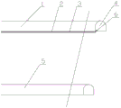
Fig. 1 is a schematic diagram of arranging an automatic pipe folding grouting pipe in an uppermost subsection stoping roadway.
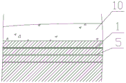
Fig. 2 is a schematic diagram of arrangement of a deep trench excavated in an uppermost subsection mining roadway and an automatic pipe folding grouting pipe.
Fig. 3 is a schematic view of grouting equipment arranged on the uppermost subsection of the communication channel.
FIG. 4 is a schematic horizontal sectional view of an arrangement of an automatic tube folding grouting tube.
Fig. 5 is a schematic view of the loose joint connection assembly of the automatic pipe folding grouting pipe (the upper half is a sectional view, and the lower half is an external view).
Fig. 6 is a schematic view of the spaced openings of the claw thread insert.
Fig. 7 is a schematic view showing the completion of the work of pre-embedding the automatic pipe folding and grouting pipe.
FIG. 8 is a schematic view of the second stage for recovery and grouting.
FIG. 9 is a schematic representation of the downward movement of the overburden as the third section is no longer grouted and recovery begins.
Fig. 10 is a schematic diagram illustrating the automatic breaking principle of the automatic pipe-breaking grouting pipe in the ore drawing process.
Detailed Description
The following further describes the embodiments of the present invention with reference to the drawings.
As shown in figure 1, the method for grouting the long-distance automatic pipe-folding covering rock by the sill pillar-free sublevel caving method comprises the steps of dividing an ore body into a plurality of stages, dividing the stages into a plurality of subsections, arranging mining roadways in each subsection in a rhombic staggered mode, and performing mining on each subsection one by one from top to bottom. The method is characterized by comprising the following steps of performing backspacing type stoping from the tail end of a stoping roadway to the input end of the stoping roadway in a segmented rock drilling, ore caving, ore removal and other work, and performing stoping one ore caving step at a time:
step one, embedding an automatic pipe folding grouting pipe
As shown in fig. 1 to 4, digging deep grooves 2 in full length at two sides of the bottom of all the uppermost subsection mining roadways 1, wherein the depth of each deep groove 2 is 30cm to 50cm, and the width of each deep groove 2 is larger than the pipe diameter of an automatic pipe folding grouting pipe 3;
extending to the uppermost subsection connecting channel 4, embedding the automatic pipe folding and grouting pipe 3 into the deep groove 2, extending the automatic pipe folding and grouting pipe 3 out of the ground at the uppermost subsection connecting channel 4 and reserving a certain length as the grouting input end, connecting the grouting input end with grouting equipment 6 through a connecting pipe fitting, burying the deep groove 2 with working surface slag, cementing and sealing the surface with concrete, and performing backspacing type stoping work of the uppermost subsection stoping roadway 1 from the tail end to the input end after the concrete is dried through, wherein fig. 7 is a schematic diagram of the situation of completing the work of embedding the automatic pipe folding and grouting pipe;
step two, overlying rock grouting
As shown in fig. 1, fig. 3 and fig. 8, when the second segmental mining roadway 5 is mined, the back-off mining is also carried out from the tail end to the input end of the second segmental mining roadway 5, a ore caving step is mined,
as shown in fig. 5 and 6, the automatic pipe folding and grouting pipe 3 of the invention is composed of a plurality of sections of PPR water pipes 31 and loose joints connecting the sections of PPR water pipes 31, the loose joints are made of PPR materials and are composed of a butt joint 35 with external screw short connection threads arranged on the outer side of the front end, a cloud head 32 and a claw-shaped threaded sleeve 33 with internal screw short connection threads, the inner diameters of the butt joint 35 and the cloud head 32 are matched with the outer diameter of the PPR water pipe 31, and a convex edge is arranged on the end face of the front end of the cloud head 32; the front end of the claw-shaped screw sleeve 33 is in a multi-claw shape, inner thread short connection threads are arranged on the inner sides of the claws, a hole is formed in the end face of the tail end, and the hole diameter is matched with the outer diameter of the tail end of the cloud head 32; the short-circuit external thread on the outer side of the front end of the butt joint 35 is matched with the short-circuit thread on the inner thread of the claw-shaped screw sleeve 33, an O-shaped sealing ring installation groove is formed in the end surface of the front end, and an O-shaped sealing ring 34 is installed in the O-shaped sealing ring installation groove; the claw-shaped threaded sleeve 33 is inserted into the cloud head 32, the claw-shaped threaded sleeve 33 is in threaded connection with the butt joint 35, and the tail ends of the butt joint 35 and the cloud head 32 are in hot-melt connection with the two sections of PPR water pipes 31 respectively to complete the connection of the two sections of PPR water pipes 31. The claw-like thread insert 33 is pulled in the axial direction to reduce the radial biting force of the thread insert, and is easily broken by the radial force.
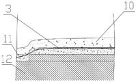
As shown in fig. 10, in the process of ore drawing, the automatic pipe-folding grouting pipe 3 is automatically broken at the loose joint by the downward pressure 7 formed by the descending of ore and rock, and is scattered in the covering rock 10, the grouting outlet of the automatic pipe-folding grouting pipe 3 is automatically adjusted to the position needing grouting currently, and 9 in the drawing is a fan-shaped medium-length hole.
After ore drawing is finished, the cover rock 10 falls to the end part of the working face, the cover rock 10 at the end part of the working face of the current second subsection mining roadway 5 is grouted in the uppermost subsection connecting road 4 by the grouting equipment 6 through the automatic pipe-folding grouting pipe 3, as shown in figure 1, since the mining roadway of the sublevel caving method without the bottom pillar is arranged in a rhombus shape, the cover rock 10 at the end part of the working face of the second subsection mining roadway 5 needs to be grouted by the automatic pipe-folding grouting pipes A and B arranged at the inner sides of the adjacent uppermost subsection mining roadway, so when the automatic pipe-folding grouting pipe 3 is connected with the grouting equipment 6, the two adjacent automatic pipe-folding grouting pipes A and B of the adjacent two uppermost subsection mining roadways can also be connected with one grouting equipment in a combined mode as shown in figure 4 until the grout flows out of the working face, water is injected for 1-2 minutes to wash the automatic pipe-folding grouting pipe 3,
the grouting of the invention adopts solid sodium silicate as grouting material, before grouting, the solid sodium silicate needs to be dissolved into grouting solution by water, and the proportion of the solid sodium silicate to the water is 1: (5-20), the proportion of the primary grouting amount to the volume of the covered rock to be grouted is 1: (5-20).
And then carrying out the stoping of the next ore caving step distance, grouting again, and stoping again until the stoping of the second subsection stoping roadway 5 is finished, namely finishing the grouting work of the overlying rock of the second subsection stoping roadway 5, and finishing the stoping and grouting work of all the second subsection stoping roadways in the same way.
The third and all following subsections including stages adopt the traditional sill pillar-free sublevel caving method to recover ores, as shown in fig. 9.
The pipe diameter of the multi-section PPR water pipe 31 is a PPR pipe with the diameter of 6 minutes or 1 inch, and the length of each section of PPR water pipe is equal to the ore caving step distance; the grouting equipment 6 adopts a water pump or a grouting machine.
Due to the adoption of the loose joint with the structure, along with the recovery of each ore caving step, one section of automatic pipe folding grouting pipe can be automatically broken in the ore rock falling process, so that a grouting port can be automatically adjusted to a position needing grouting, the grouting of the overlying rock is facilitated, the operation is convenient, the implementation is simple, along with the downward movement of the overlying rock, the recovery of the third section and all the sections below the third section is performed ore drawing under the protection of the grouting overlying rock, the effect of preventing the waste rock from being mixed is achieved, and the purpose of efficient ore drawing under the grouting overlying rock is finally achieved.
In the figure: 8 is a collapsed ore; 11, grouting overlay rock; 12 is a body to be mined; a and B are automatic pipe folding and grouting pipes arranged on the inner sides of two adjacent uppermost subsection stoping roadways.
Claims (6)
1. A long-distance automatic pipe-folding covering rock grouting method by a sill pillar-free sublevel caving method comprises the steps of dividing an ore body into a plurality of stages, dividing the stages into a plurality of subsections, arranging mining roadways in each subsection in a rhombic staggered mode, and performing mining on each subsection from top to bottom one by one; the method is characterized by comprising the following steps of performing backspacing type stoping from the tail end of a stoping roadway to the input end of the stoping roadway in a segmented rock drilling, ore caving, ore removal and other work, and performing stoping one ore caving step at a time:
step one, embedding an automatic pipe folding grouting pipe
Digging deep grooves in full length on two sides of the bottom of all the uppermost-section stoping roadways, extending the deep grooves to the uppermost-section connecting channel, embedding the automatic pipe folding grouting pipes into the deep grooves, extending the automatic pipe folding grouting pipes out of the ground at the uppermost-section connecting channel and reserving a certain length as the inlet ends of grouting, connecting the automatic pipe folding grouting pipes with grouting equipment through connecting pipe fittings, burying the deep grooves with working surface slag, cementing and sealing the surfaces with concrete, and performing backspacing type stoping work of the uppermost-section stoping roadway from the tail end to the inlet ends when the concrete is completely dried;
step two, overlying rock grouting
When a second sectional stoping roadway is mined, the retrogression type stoping is carried out from the tail end to the input end of the second sectional stoping roadway, a caving step is mined, in the ore drawing process, the automatic pipe folding grouting pipe is automatically broken off by one section at the loose joint under the action of downward pressure formed by descending of ore and rock and is scattered in covering rock, the grouting outlet of the automatic pipe folding grouting pipe is automatically adjusted to the position needing grouting at present,
after ore drawing is finished, the covering rock falls to the end part of the working face, grouting is carried out on the covering rock at the end part of the working face of the current second-segment mining roadway in the uppermost-segment connecting road through an automatic pipe-folding grouting pipe by using grouting equipment until grout flows out of the working face, then water is injected for 1-2 minutes to wash the automatic pipe-folding grouting pipe,
performing stoping of the next ore caving step, grouting, and stoping again until the stoping of the second sublevel stoping roadway is finished, namely completing the stoping and grouting work of the second sublevel stoping roadway cover rock, and completing the stoping and grouting work of all second sublevel stoping roadways in the same way;
and the third section and all the following sections including all the stages adopt the traditional sill pillar-free sectional caving method to recover the ore.
2. The grouting method for the remote automatic pipe folding and covering rock by the bottom-pillar-free sublevel caving method according to claim 1, wherein the depth of the deep groove is 30 cm-50 cm, and the width of the deep groove is larger than the pipe diameter of the automatic pipe folding and grouting pipe.
3. The method for grouting the covering rock by remotely and automatically folding the pipe by the sublevel caving method without the bottom pillar as recited in claim 1, wherein the automatic pipe folding and grouting pipe is composed of a plurality of sections of PPR water pipes and a loose joint for connecting each section of PPR water pipe, the loose joint is composed of a butt joint with an external short-circuit thread arranged outside the front end, a cloud head and a claw-shaped threaded sleeve with an internal short-circuit thread, the inner diameters of the butt joint and the cloud head are matched with the outer diameter of the PPR water pipe, and a convex edge is arranged on the front end face of the cloud head; the front end of the claw-shaped screw sleeve is in a multi-claw shape, inner-thread short connection threads are arranged on the inner sides of the claws, a hole is formed in the end face of the tail end, and the hole diameter is matched with the outer diameter of the tail end of the cloud head; the short-circuit external thread on the outer side of the flat connection front end is matched with the claw-shaped screw sleeve internal thread short-circuit thread, an O-shaped sealing ring installation groove is formed in the end face of the front end, and an O-shaped sealing ring is installed in the O-shaped sealing ring installation groove; the claw-shaped threaded sleeve is inserted into the cloud head, the claw-shaped threaded sleeve is connected with the flush joint through threads, and the tail ends of the flush joint and the cloud head are respectively in hot-melt connection with the two sections of PPR water pipes to complete the connection of the two sections of PPR water pipes.
4. The method for grouting the covering rock by remotely and automatically folding the pipe by the pillarless sublevel caving method according to claim 1, wherein the pipe diameter of the plurality of sections of PPR water pipes is 6 minutes or 1 inch PPR pipe, and the length of each section of PPR water pipe is equal to the ore caving step.
5. The method for grouting the covering rock by remotely and automatically breaking the pipe according to the bottom-pillar-free sublevel caving method, wherein a water pump or a grouting machine is adopted as grouting equipment.
6. The grouting method for the long-distance automatic pipe-folding cover rock without the bottom pillar by the sublevel caving method according to claim 1, wherein solid sodium silicate is adopted for grouting as a grouting material, water is required to be dissolved into a grouting solution before grouting, and the ratio of the solid sodium silicate to the water is 1: (5-20), the proportion of the primary grouting amount to the volume of the covered rock to be grouted is 1: (5-20).
Priority Applications (1)
| Application Number | Priority Date | Filing Date | Title |
|---|---|---|---|
| CN202110588395.1A CN113236253B (en) | 2021-05-28 | 2021-05-28 | Remote automatic pipe folding cover rock grouting method by using bottom column-free sectional caving method |
Applications Claiming Priority (1)
| Application Number | Priority Date | Filing Date | Title |
|---|---|---|---|
| CN202110588395.1A CN113236253B (en) | 2021-05-28 | 2021-05-28 | Remote automatic pipe folding cover rock grouting method by using bottom column-free sectional caving method |
Publications (2)
| Publication Number | Publication Date |
|---|---|
| CN113236253A true CN113236253A (en) | 2021-08-10 |
| CN113236253B CN113236253B (en) | 2023-04-28 |
Family
ID=77139288
Family Applications (1)
| Application Number | Title | Priority Date | Filing Date |
|---|---|---|---|
| CN202110588395.1A Active CN113236253B (en) | 2021-05-28 | 2021-05-28 | Remote automatic pipe folding cover rock grouting method by using bottom column-free sectional caving method |
Country Status (1)
| Country | Link |
|---|---|
| CN (1) | CN113236253B (en) |
Citations (16)
| Publication number | Priority date | Publication date | Assignee | Title |
|---|---|---|---|---|
| US4603886A (en) * | 1984-03-26 | 1986-08-05 | Vetco Offshore, Inc. | Snap type pipe connector |
| US5131687A (en) * | 1989-05-29 | 1992-07-21 | Autobrevets | Device for making a sealed connection between a tube and a flexible hose |
| DE4242236C1 (en) * | 1992-12-15 | 1994-02-03 | Puspas Armaturen Gmbh | Wall-box for polyethylene@ pipe - has annular space between pipe and protective tube filled with polyurethane-based plastic sealant |
| JPH06330543A (en) * | 1993-05-25 | 1994-11-29 | Tomakomaishi | Fire hydrant with breakable joint |
| AUPR993902A0 (en) * | 2002-01-11 | 2002-01-31 | Fergusson, Jeffrey Robert | Longwall mining method and apparatus |
| TW578829U (en) * | 2002-06-20 | 2004-03-01 | Yung-Tsai Shen | Improved structure of fluid convey member |
| CN2623867Y (en) * | 2003-06-06 | 2004-07-07 | 长沙矿冶研究院 | Single-tube core drill |
| CN2903374Y (en) * | 2006-05-09 | 2007-05-23 | 中国矿业大学 | Fluid filling hole sealing device capable of cutting |
| CN102619515A (en) * | 2012-04-26 | 2012-08-01 | 鞍钢集团矿业公司 | Top-filled high-end-wall pillarless sublevel caving method extraction technique |
| CN203384534U (en) * | 2013-08-13 | 2014-01-08 | 中煤科工集团重庆研究院 | Self-adaption flexible ground well casing protective device |
| CN105397210A (en) * | 2015-12-22 | 2016-03-16 | 杨杰 | Slotting device for forming steel wire thread sleeve fractured slot |
| CN207093968U (en) * | 2017-09-04 | 2018-03-13 | 华仪电气股份有限公司 | A kind of loose joint head assembly |
| CN107829742A (en) * | 2017-11-27 | 2018-03-23 | 西北矿冶研究院 | Caving-filling-open stope-caving mining method |
| CN109235476A (en) * | 2018-11-05 | 2019-01-18 | 谢宁汉 | Deep foundation pit support earth-retaining erection water-proof method and its device |
| CN209162862U (en) * | 2018-11-05 | 2019-07-26 | 谢宁汉 | Deep foundation pit support earth-retaining water barrier device |
| CN110185441A (en) * | 2019-05-24 | 2019-08-30 | 中国地质科学院地质力学研究所 | A kind of urgent sluicing component of hydrofracturing measuring device |
-
2021
- 2021-05-28 CN CN202110588395.1A patent/CN113236253B/en active Active
Patent Citations (16)
| Publication number | Priority date | Publication date | Assignee | Title |
|---|---|---|---|---|
| US4603886A (en) * | 1984-03-26 | 1986-08-05 | Vetco Offshore, Inc. | Snap type pipe connector |
| US5131687A (en) * | 1989-05-29 | 1992-07-21 | Autobrevets | Device for making a sealed connection between a tube and a flexible hose |
| DE4242236C1 (en) * | 1992-12-15 | 1994-02-03 | Puspas Armaturen Gmbh | Wall-box for polyethylene@ pipe - has annular space between pipe and protective tube filled with polyurethane-based plastic sealant |
| JPH06330543A (en) * | 1993-05-25 | 1994-11-29 | Tomakomaishi | Fire hydrant with breakable joint |
| AUPR993902A0 (en) * | 2002-01-11 | 2002-01-31 | Fergusson, Jeffrey Robert | Longwall mining method and apparatus |
| TW578829U (en) * | 2002-06-20 | 2004-03-01 | Yung-Tsai Shen | Improved structure of fluid convey member |
| CN2623867Y (en) * | 2003-06-06 | 2004-07-07 | 长沙矿冶研究院 | Single-tube core drill |
| CN2903374Y (en) * | 2006-05-09 | 2007-05-23 | 中国矿业大学 | Fluid filling hole sealing device capable of cutting |
| CN102619515A (en) * | 2012-04-26 | 2012-08-01 | 鞍钢集团矿业公司 | Top-filled high-end-wall pillarless sublevel caving method extraction technique |
| CN203384534U (en) * | 2013-08-13 | 2014-01-08 | 中煤科工集团重庆研究院 | Self-adaption flexible ground well casing protective device |
| CN105397210A (en) * | 2015-12-22 | 2016-03-16 | 杨杰 | Slotting device for forming steel wire thread sleeve fractured slot |
| CN207093968U (en) * | 2017-09-04 | 2018-03-13 | 华仪电气股份有限公司 | A kind of loose joint head assembly |
| CN107829742A (en) * | 2017-11-27 | 2018-03-23 | 西北矿冶研究院 | Caving-filling-open stope-caving mining method |
| CN109235476A (en) * | 2018-11-05 | 2019-01-18 | 谢宁汉 | Deep foundation pit support earth-retaining erection water-proof method and its device |
| CN209162862U (en) * | 2018-11-05 | 2019-07-26 | 谢宁汉 | Deep foundation pit support earth-retaining water barrier device |
| CN110185441A (en) * | 2019-05-24 | 2019-08-30 | 中国地质科学院地质力学研究所 | A kind of urgent sluicing component of hydrofracturing measuring device |
Non-Patent Citations (3)
| Title |
|---|
| JIAN LI等: "Control Research on Broken Coal-Wall and Rroof in the Complex Geological Conditions" * |
| 周宝坤;赵德智;姚宝顺;高聪;谷鑫;陈晓青;: "挑檐式结构无底柱阶段崩落采矿法试验研究" * |
| 陈晓云;李光;王子介;范立鹏;胡颖鹏;: "眼前山铁矿破碎区域斜坡道联合支护研究" * |
Also Published As
| Publication number | Publication date |
|---|---|
| CN113236253B (en) | 2023-04-28 |
Similar Documents
| Publication | Publication Date | Title |
|---|---|---|
| CN104863629B (en) | A kind of method taking out absciss layer gas and draining slip casting under overlying strata using combined drilling and counterboring | |
| CN103306687B (en) | Soft rock tunnel long cantilever horizontal jet grouting Deformation control construction method | |
| CN100593630C (en) | Caving zone edge inclined drill hole bushing burying method for extracting and discharging gas for goaf and adjacent layer | |
| CN103899350B (en) | Fully mechanized coal face frame carries top coal gas drainage system | |
| CN104975868A (en) | Top plate high-position boring large-diameter long-drill-hole gas extraction method based on directional drilling | |
| CN104481540A (en) | Method for controlling multiple coal mining hazards by high level borehole grouting | |
| CN111335944B (en) | Coal face gangue slurry pipeline collaborative filling method | |
| CN105804786B (en) | A kind of weak seam bottom plate layer-through drilling pressure rushes anti-reflection method | |
| CN108412453A (en) | A kind of coal mining water controls system and construction method altogether with gas | |
| CN112253115B (en) | Near-horizontal coal seam roadway type cemented filling mining method | |
| CN113202475A (en) | Filling caving mining method | |
| CN110043309A (en) | Close the method for arranging and well bore installation method of the gas drainage well of coal mine | |
| CN109899105B (en) | Low-level multi-order cross-layer drilling gas extraction method for coal-rock interbed coal seam | |
| CN105804754A (en) | Coal uncovering method for mining shaft with coal seam as main water-bearing layer | |
| CN106988760A (en) | Facility-sliding strata tunnel portal reinforcing construction and construction method | |
| CN114837663B (en) | Construction method for improving recovery rate of fault waterproof coal pillar through ground pre-grouting | |
| CN113153295A (en) | Mining method for extremely thick hard coal | |
| CN108505999A (en) | A kind of high prominent more lane method for arranging of working face of coal seam | |
| CN203702070U (en) | Coal mine low pumping lane borehole slag-returning sealing apparatus | |
| CN110778317A (en) | Construction method for ground grouting filling drilling structure in caving zone in mining process | |
| CN114294046A (en) | Up-down three-dimensional extraction method for full-coverage well in coal mine area | |
| CN103742098A (en) | Device and method for sealing hole by using returned slag of layer-through drill hole of low drainage roadway of coal mine | |
| CN111810221B (en) | Method for treating gas on mining face through pumping drainage of U-parallel U + upper corner | |
| CN113236253A (en) | Remote automatic pipe folding and covering rock grouting method by non-bottom-pillar sublevel caving method | |
| CN115199269A (en) | Multi-disaster integrated prevention and control method for island outburst coal seam strong and weak coupling structure |
Legal Events
| Date | Code | Title | Description |
|---|---|---|---|
| PB01 | Publication | ||
| PB01 | Publication | ||
| SE01 | Entry into force of request for substantive examination | ||
| SE01 | Entry into force of request for substantive examination | ||
| GR01 | Patent grant | ||
| GR01 | Patent grant |