CN113228564B - Stamping processing method and device - Google Patents
Stamping processing method and device Download PDFInfo
- Publication number
- CN113228564B CN113228564B CN201880100455.7A CN201880100455A CN113228564B CN 113228564 B CN113228564 B CN 113228564B CN 201880100455 A CN201880100455 A CN 201880100455A CN 113228564 B CN113228564 B CN 113228564B
- Authority
- CN
- China
- Prior art keywords
- ptp
- network node
- ptp messages
- target
- time stamp
- Prior art date
- Legal status (The legal status is an assumption and is not a legal conclusion. Google has not performed a legal analysis and makes no representation as to the accuracy of the status listed.)
- Active
Links
Images


Classifications
-
- H—ELECTRICITY
- H04—ELECTRIC COMMUNICATION TECHNIQUE
- H04J—MULTIPLEX COMMUNICATION
- H04J3/00—Time-division multiplex systems
- H04J3/02—Details
- H04J3/06—Synchronising arrangements
- H04J3/0635—Clock or time synchronisation in a network
- H04J3/0638—Clock or time synchronisation among nodes; Internode synchronisation
- H04J3/0658—Clock or time synchronisation among packet nodes
- H04J3/0661—Clock or time synchronisation among packet nodes using timestamps
- H04J3/0667—Bidirectional timestamps, e.g. NTP or PTP for compensation of clock drift and for compensation of propagation delays
-
- H—ELECTRICITY
- H04—ELECTRIC COMMUNICATION TECHNIQUE
- H04J—MULTIPLEX COMMUNICATION
- H04J3/00—Time-division multiplex systems
- H04J3/02—Details
- H04J3/06—Synchronising arrangements
- H04J3/0635—Clock or time synchronisation in a network
- H04J3/0685—Clock or time synchronisation in a node; Intranode synchronisation
- H04J3/0697—Synchronisation in a packet node
-
- H—ELECTRICITY
- H04—ELECTRIC COMMUNICATION TECHNIQUE
- H04L—TRANSMISSION OF DIGITAL INFORMATION, e.g. TELEGRAPHIC COMMUNICATION
- H04L43/00—Arrangements for monitoring or testing data switching networks
- H04L43/08—Monitoring or testing based on specific metrics, e.g. QoS, energy consumption or environmental parameters
- H04L43/0852—Delays
-
- H—ELECTRICITY
- H04—ELECTRIC COMMUNICATION TECHNIQUE
- H04L—TRANSMISSION OF DIGITAL INFORMATION, e.g. TELEGRAPHIC COMMUNICATION
- H04L43/00—Arrangements for monitoring or testing data switching networks
- H04L43/10—Active monitoring, e.g. heartbeat, ping or trace-route
- H04L43/106—Active monitoring, e.g. heartbeat, ping or trace-route using time related information in packets, e.g. by adding timestamps
Landscapes
- Engineering & Computer Science (AREA)
- Computer Networks & Wireless Communication (AREA)
- Signal Processing (AREA)
- Health & Medical Sciences (AREA)
- Cardiology (AREA)
- General Health & Medical Sciences (AREA)
- Environmental & Geological Engineering (AREA)
- Data Exchanges In Wide-Area Networks (AREA)
- Synchronisation In Digital Transmission Systems (AREA)
Abstract
本申请涉及通信技术领域,公开了一种打戳处理方法及装置,用以提高打戳处理的准确性,进而保证延时测量的准确性。该方法为:网络节点对以太端口接收到的多个PTP报文分别打入第一时戳;其中,所述以太端口具有多个lane,所述多个PTP报文为所述网络节点通过所述多个lane接收的;所述网络节点在所述多个PTP报文跨过时钟域后,将所述多个PTP报文中分别打入第一时戳的第一时戳值,更新为所述多个lane中目标lane接收的目标PTP报文对应的目标时戳值;所述网络节点根据所述目标时戳值与所述多个PTP报文的发送时戳的时戳值的差值,确定所述网络节点与发送所述多个PTP报文的网络节点间的延时。
The present application relates to the field of communication technology, and discloses a stamping processing method and device, which are used to improve the accuracy of stamping processing, thereby ensuring the accuracy of delay measurement. The method is as follows: a network node enters first time stamps into a plurality of PTP messages received by an Ethernet port; wherein the Ethernet port has a plurality of lanes, and the plurality of PTP messages are obtained by the network node through the received by the multiple lanes; after the multiple PTP messages cross the clock domain, the network node updates the first timestamp values of the first timestamps in the multiple PTP messages to The target time stamp value corresponding to the target PTP message received by the target lane in the multiple lanes; the network node according to the difference between the target time stamp value and the time stamp value of the sending time stamp of the multiple PTP messages value, to determine the delay between the network node and the network node sending the multiple PTP messages.
Description
技术领域technical field
本申请涉及通信技术领域,特别涉及一种打戳处理方法及装置。The present application relates to the technical field of communications, and in particular to a stamping processing method and device.
背景技术Background technique
随着以太端口速率的不断提升,需要支持精确时间同步协议(precision timeprotocol,PTP)的以太端口的带宽也越来越高,如100千兆以太网(gigabit ethernet,GE)、200GE和400GE等,当前单数据通路(lane)的以太端口已不足以支撑PTP协议功能的部署,需要在多lane的以太端口部署PTP协议功能。在多lane以太端口应用PTP报文测量两网络节点之间的延时时,对于发送方向,PTP协议要求同一以太端口的多个lane一定要对齐发送,即同一以太端口的多个lane同一拍的多个PTP报文发送的时戳的时戳值相同,受多个lane的传输环境的影响,如多个lane的光纤传输等,多个lane无法保证延时一致,因此PTP协议定义,在接收方向,需要把多个lane接收PTP报文的时戳的时戳值,补偿对齐到同一基准lane上,当前定义的基准lane为延时最长的lane。As the rate of Ethernet ports continues to increase, the bandwidth of Ethernet ports that need to support precision time synchronization protocols (precision time protocol, PTP) is also increasing, such as 100 Gigabit Ethernet (gigabit ethernet, GE), 200GE and 400GE, etc., The current single data path (lane) Ethernet port is not enough to support the deployment of the PTP protocol function, and the PTP protocol function needs to be deployed on the multi-lane Ethernet port. When PTP packets are used to measure the delay between two network nodes on a multi-lane Ethernet port, for the sending direction, the PTP protocol requires that multiple lanes of the same Ethernet port must be aligned and sent, that is, multiple lanes of the same Ethernet port are shot at the same time The time stamp value of multiple PTP packets sent is the same, which is affected by the transmission environment of multiple lanes, such as optical fiber transmission of multiple lanes, etc. Multiple lanes cannot guarantee consistent delays. Therefore, the PTP protocol definition, when receiving Direction, the time stamp values of the time stamps received by multiple lanes for PTP packets need to be compensated and aligned to the same reference lane, and the currently defined reference lane is the lane with the longest delay.
现有技术中,在接收方向,网络节点将以太端口每个lane接收的PTP报文通过延时差对齐缓冲器(deskew fifo)进行延时差对齐,其所述fifo指先进先出缓冲器(firstinput first output),网络节点通过deskew fifo将每个lane接收的PTP报文缓存后,通过deskew fifo读出缓存的每个lane接收的PTP报文,用以实现将各lane接收的PTP报文的延时差对齐,网络节点根据每个lane接收的PTP报文读出的时间,与PTP报文在deskew fifo中缓存的时长的差值,生成接收PTP报文的时戳,并根据多个lane相对于基准lane的延时差异,将多个lane接收PTP报文的时戳的时戳值,补偿至基准lane接收PTP报文的时戳的时戳值,以便对网络节点间的延时进行测量。In the prior art, in the receiving direction, the network node performs delay difference alignment on the PTP message received by each lane of the Ethernet port through a delay difference alignment buffer (deskew fifo), and the fifo refers to a first-in-first-out buffer ( firstinput first output), the network node caches the PTP packets received by each lane through the deskew fifo, and reads out the cached PTP packets received by each lane through the deskew fifo, so as to implement the PTP packets received by each lane Delay difference alignment, the network node generates the time stamp of receiving the PTP message according to the difference between the read time of the PTP message received by each lane and the buffering time of the PTP message in deskew fifo, and according to the time stamp of multiple lanes Compared with the delay difference of the reference lane, the time stamp value of the time stamp of multiple lanes receiving the PTP message is compensated to the time stamp value of the time stamp of the reference lane receiving the PTP message, so as to optimize the delay between network nodes Measurement.
然而,在多种场景下会出现异步deskew fifo的情况,如在多速率以太端口混用同一组介质访问控制层(media access control,MAC)逻辑时,网络节点的以太端口中出现deskew fifo写入PTP报文所遵循的写时钟(wr_clk)和读取PTP报文所遵循的读时钟(rd_clk)不同,为异步deskew fifo,PTP报文在deskew fifo过程中跨过了时钟域,因wr_clk和rd_clk的频率和/或相位不同,导致网络节点生成的接收PTP报文的时戳不准确。示例性的,以lane1接收的PTP报文1为例,网络节点根据wr_clk在deskew fifo写入PTP报文1的时间为2018年11月23日19时23分1.02秒,因为rd_clk和wr_clk的频率和/或相位不同,网络节点读出的deskew fifo缓存PTP报文1的时长为0.1秒,在deskew fifo读出PTP报文1的时间为2018年11月23日19时23分1.13秒,导致计算出的PTP报文1的时戳的时戳值为2018年11月23日19时23分1.03秒,与2018年11月23日19时23分1.02秒存在着误差,进而导致网络节点间延时测量不准确。However, asynchronous deskew fifos will appear in various scenarios. For example, when multi-rate Ethernet ports are mixed with the same set of media access control (MAC) logic, deskew fifos will be written to PTP in the Ethernet port of the network node. The write clock (wr_clk) that the message follows is different from the read clock (rd_clk) that reads the PTP message. It is an asynchronous deskew fifo, and the PTP message crosses the clock domain during the deskew fifo process, because the wr_clk and rd_clk The frequencies and/or phases are different, resulting in inaccurate time stamps generated by network nodes for receiving PTP messages. Exemplarily, taking the
发明内容Contents of the invention
本申请提供一种打戳处理方法及装置,用以解决现有技术中存在的因打戳处理不准确,导致网络节点间延时测量不准确的问题。The present application provides a stamping processing method and device, which are used to solve the problem in the prior art that the time delay measurement between network nodes is inaccurate due to inaccurate stamping processing.
第一方面,本申请提供了一种打戳处理方法,该方法可以通过网络节点实现,该方法包括:网络节点对以太端口接收到的多个PTP报文分别打入第一时戳;其中,所述以太端口具有多个lane,所述多个PTP报文为所述网络节点通过所述多个lane接收的;所述网络节点在所述多个PTP报文跨过时钟域后,将所述多个PTP报文中分别打入第一时戳的第一时戳值,更新为所述多个PTP报文中目标PTP报文对应的目标时戳值;其中,所述目标PTP报文为所述多个lane中目标lane接收的PTP报文,所述目标lane为延时最短的lane或延时最长的lane;所述网络节点根据所述目标时戳值与所述多个PTP报文的发送时戳的时戳值的差值,确定所述网络节点与发送所述多个PTP报文的网络节点间的延时。在本申请中,网络节点在以太端口每个lane接收的PTP报文跨时钟域之前,即在每个lane接收的PTP报文写入deskewfifo之前进行打戳,在所述多个PTP报文跨过时钟域后,即在deskew fifo输出所述多个PTP报文时,将每个lane接收的PTP报文打戳的时戳值补偿到指定的目标lane接收的PTP报文的时戳值,实现延时差对齐,避免了异步deskew fifo导致的误差,提高了打戳处理的准确性,保证了网络节点间延时确定的准确性;同时因打戳发生在PTP报文写入deskew fifo之前,无需deskew fifo的写时钟与读时钟的频率保持一致或倍数关系,进而可以使不同速率的以太端口可以共享一套打戳处理逻辑,且每个以太端口都支持高精度的打戳处理,也提高了打戳处理的适用范围。In the first aspect, the present application provides a stamping processing method, which can be implemented by a network node, and the method includes: the network node enters first time stamps into a plurality of PTP messages received by the Ethernet port; wherein, The Ethernet port has multiple lanes, and the multiple PTP messages are received by the network node through the multiple lanes; after the multiple PTP messages cross the clock domain, the network node sends the The first timestamp value of the first timestamp in the multiple PTP messages is updated to the target timestamp value corresponding to the target PTP message in the multiple PTP messages; wherein, the target PTP message For the PTP message received by the target lane in the multiple lanes, the target lane is the lane with the shortest delay or the lane with the longest delay; the network node according to the target timestamp value and the multiple PTP The difference between the time stamp values of the sending time stamps of the messages determines the delay between the network node and the network node sending the multiple PTP messages. In this application, the network node stamps before the PTP message received by each lane of the Ethernet port crosses the clock domain, that is, before the PTP message received by each lane is written into deskewfifo, and the multiple PTP messages cross the clock domain. After passing the clock domain, that is, when the deskew fifo outputs the multiple PTP messages, the timestamp value of the PTP message stamped by each lane is compensated to the timestamp value of the PTP message received by the specified target lane, Realize the alignment of delay difference, avoid the error caused by asynchronous deskew fifo, improve the accuracy of stamping processing, and ensure the accuracy of delay determination between network nodes; at the same time, stamping occurs before the PTP message is written into deskew fifo , it is not necessary to maintain the same or multiple relationship between the frequency of deskew fifo write clock and read clock, so that Ethernet ports with different rates can share a set of stamping processing logic, and each Ethernet port supports high-precision stamping processing, and also The scope of application of stamping processing has been improved.
在一种可能的设计中,所述网络节点对以太端口接收到的多个PTP报文分别打入第一时戳,包括:所述网络节点对以太端口接收到的多个PTP报文的第一个比特(bit)分别打入第一时戳。通过这种方式,便于在延时差对齐时,快速将每个lane接收的PTP报文打入的时戳的时戳值补偿到目标lane接收的目标PTP报文打入时戳的时戳值。In a possible design, the network node enters first time stamps into the multiple PTP messages received by the Ethernet port respectively, including: the first time stamp of the multiple PTP messages received by the network node on the Ethernet port One bit (bit) is entered into the first time stamp respectively. In this way, it is convenient to quickly compensate the time stamp value of the time stamp of the PTP message received by each lane to the time stamp value of the target PTP message received by the target lane when the delay difference is aligned. .
在一种可能的设计中,所述网络节点对以太端口接收到的多个PTP报文分别打入第一时戳,包括:所述网络节点对以太端口接收到的多个PTP报文的设定bit分别打入第一时戳;所述网络节点基于所述多个PTP报文分别对应所述设定bit与第一个bit的距离,确定所述多个PTP报文分别对应第一个bit至设定bit的第一传输时长;所述网络节点将所述多个PTP报文中分别打入第一时戳的第一时戳值,校正为所述第一时戳值与所述PTP报文对应的第一传输时长的差值。通过这种方式,丰富了网络节点的打戳方案,便于根据网络节点所处的网络环境,选择适合的打戳方案。In a possible design, the network node enters first time stamps into the multiple PTP messages received by the Ethernet port, including: the setting of the multiple PTP messages received by the Ethernet port by the network node The fixed bits are respectively entered into the first timestamp; the network node determines that the multiple PTP messages correspond to the first bit based on the distances between the set bits and the first bit respectively. The first transmission duration from one bit to the set bit; the network node corrects the first time stamp values of the first time stamps into the multiple PTP messages so that the first time stamp value is the same as the first time stamp value The difference between the first transmission duration corresponding to the PTP packet. In this way, the stamping schemes of the network nodes are enriched, and it is convenient to select a suitable stamping scheme according to the network environment where the network nodes are located.
在一种可能的设计中,所述网络节点对以太端口接收到的多个PTP报文分别打入第一时戳,包括:所述网络节点按照测量周期,根据当前测量周期以太端口的多个lane分别对应的打戳时间,对所述以太端口接收的多个PTP报文分别打入第一时戳;所述网络节点基于所述多个PTP报文分别对应打入第一时戳的目标bit与第一个bit的距离,确定所述多个PTP报文分别对应第一个bit至打入第一时戳的目标bit的第二传输时长;所述网络节点将所述多个PTP报文中分别打入第一时戳的第一时戳值,校正为所述第一时戳值与所述PTP报文对应的第二传输时长的差值。通过这种方式,丰富了网络节点的打戳方案,便于根据网络节点所处的网络环境,选择适合的打戳方案。In a possible design, the network node respectively inserts first time stamps into the multiple PTP messages received by the Ethernet port, including: the network node according to the measurement period, according to the multiple PTP packets of the current measurement period Stamping times corresponding to lanes respectively, respectively entering first time stamps into the multiple PTP messages received by the Ethernet port; the network node is based on the targets of the multiple PTP messages respectively corresponding to the first time stamps The distance between the bit and the first bit is used to determine the second transmission duration between the first bit and the target bit of the first time stamp for the multiple PTP messages; the network node sends the multiple PTP messages The first time stamp value of the first time stamp is respectively entered in the text, and corrected to be the difference between the first time stamp value and the second transmission duration corresponding to the PTP message. In this way, the stamping schemes of the network nodes are enriched, and it is convenient to select a suitable stamping scheme according to the network environment where the network nodes are located.
在一种可能的设计中,所述将所述多个PTP报文中分别打入第一时戳的第一时戳值,更新为所述多个PTP报文中目标PTP报文对应的目标时戳值,包括:所述网络节点根据所述多个PTP报文中分别打入第一时戳的第一时戳值与接收所述PTP报文的lane相对于目标lane的延时差异的和,对所述多个PTP报文中分别打入的第一时戳的第一时戳值进行更新;其中,多个lane分别相对于目标lane的延时差异,是根据在跨时钟域之前,对所述目标lane接收的PTP报文的设定bit打入第二时戳的第二时戳值,分别与所述多个lane接收的PTP报文的设定bit打入第二时戳的第二时戳值的差确定的。通过这种方式,无需在每次打戳处理时对目标PTP报文进行识别,简化了打戳处理的流程。In a possible design, the first timestamp values respectively entered into the first timestamps in the multiple PTP messages are updated to the target values corresponding to the target PTP messages in the multiple PTP messages. The time stamp value includes: the first time stamp value of the first time stamp respectively entered by the network node in the plurality of PTP messages and the delay difference between the lane receiving the PTP message and the target lane and, updating the first timestamp values of the first timestamps respectively entered in the plurality of PTP messages; wherein, the delay differences of the multiple lanes with respect to the target lane are based on , enter the second timestamp value of the second timestamp into the set bit of the PTP message received by the target lane, and enter the second timestamp with the set bit of the PTP message received by the multiple lanes respectively Determined by the difference of the second timestamp value. In this way, there is no need to identify the target PTP message every time stamping is processed, which simplifies the process of stamping.
在一种可能的设计中,所述确定目标lane的过程包括:所述网络节点在所述以太端口建链时,将对所述以太端口接收的多个PTP报文分别打入的第三时戳的第三时戳值中,最大时戳值的目标PTP报文所对应的lane或最小时戳值的目标PTP报文所述对应的lane,确定为目标lane。通过这种方式,有助于目标lane的准确确定,有助于保证打戳处理的准确性。In a possible design, the process of determining the target lane includes: when the network node establishes a link on the Ethernet port, the network node enters a plurality of PTP messages received by the Ethernet port at the third time In the third timestamp value of the timestamp, the lane corresponding to the target PTP message with the largest timestamp value or the lane corresponding to the target PTP message with the smallest timestamp value is determined as the target lane. In this way, it is helpful to accurately determine the target lane and to ensure the accuracy of stamping processing.
第二方面,本申请提供了一种打戳处理装置,该装置具有实现上述第一方面和任一种可能的设计中方法的功能。所述功能可以通过硬件实现,也可以通过硬件执行相应的软件实现。所述硬件或软件包括一个或多个与上述功能相对应的模块。In a second aspect, the present application provides a stamping processing device, which has the function of realizing the above-mentioned first aspect and any possible design method. The functions described above may be implemented by hardware, or may be implemented by executing corresponding software on the hardware. The hardware or software includes one or more modules corresponding to the above functions.
在一个可能的设计中,该装置可以是芯片或者集成电路。In one possible design, the device may be a chip or an integrated circuit.
在一个可能的设计中,该装置包括收发器和处理器,处理器用于执行一组程序,当程序被执行时,所述装置可以执行上述第一方面和任一种可能的设计中所述的方法。In a possible design, the device includes a transceiver and a processor, and the processor is used to execute a set of programs. When the programs are executed, the device can execute the above-mentioned first aspect and any of the possible designs. method.
在一个可能的设计中,该装置还包括存储器,用于存储所述处理器执行的程序。In a possible design, the device further includes a memory, configured to store programs executed by the processor.
在一个可能的设计中,该装置为网络节点。In one possible design, the device is a network node.
第三方面,本申请提供了一种计算机存储介质,存储有计算机程序,该计算机程序包括用于执行上述第一方面或者第一方面的任意一种可能的设计中方法的指令。In a third aspect, the present application provides a computer storage medium storing a computer program, and the computer program includes instructions for executing the above-mentioned first aspect or any possible design method of the first aspect.
第四方面,本申请提供了一种包含指令的计算机程序产品,当其在网络节点上运行时,使得网络节点执行上述第一方面或者第一方面的任意一种可能的设计中的方法。In a fourth aspect, the present application provides a computer program product containing instructions, which, when running on a network node, causes the network node to execute the method in the above-mentioned first aspect or any possible design of the first aspect.
第五方面,提供一种芯片,所述芯片与存储器相连,用于读取并执行所述存储器中存储的软件程序,以实现上述第一方面或上述第一方面的任意一种可能的设计中的方法。In a fifth aspect, a chip is provided, the chip is connected to a memory, and is used to read and execute a software program stored in the memory, so as to realize the above-mentioned first aspect or any possible design of the above-mentioned first aspect Methods.
附图说明Description of drawings
图1为本申请实施例中延时请求响应机制示意图;FIG. 1 is a schematic diagram of a delay request response mechanism in an embodiment of the present application;
图2为本申请实施例中lane的deskew fifo机制示意图;Fig. 2 is the schematic diagram of the deskew fifo mechanism of lane in the embodiment of the present application;
图3A为本申请实施例中通信系统架构示意图之一;FIG. 3A is one of the schematic diagrams of the communication system architecture in the embodiment of the present application;
图3B为本申请实施例中通信系统架构示意图之二;FIG. 3B is the second schematic diagram of the communication system architecture in the embodiment of the present application;
图4为本申请实施例中通信系统架构示意图之三;FIG. 4 is the third schematic diagram of the communication system architecture in the embodiment of the present application;
图5为本申请实施例中打戳处理过程示意图;FIG. 5 is a schematic diagram of the stamping process in the embodiment of the present application;
图6为本申请实施例中网络节点的结构示意图之一;FIG. 6 is one of the schematic structural diagrams of the network nodes in the embodiment of the present application;
图7为本申请实施例中网络节点的结构示意图之二。FIG. 7 is a second schematic structural diagram of a network node in an embodiment of the present application.
具体实施方式detailed description
本申请提供一种打戳处理方法及装置,用以提高打戳处理的准确性,以保证网络节点间延时测量的准确性,其中,方法和设备是基于同一发明构思的,由于方法及设备解决问题的原理相似,因此设备与方法的实施可以相互参见,重复之处不再赘述。The present application provides a stamping processing method and device to improve the accuracy of stamping processing to ensure the accuracy of delay measurement between network nodes, wherein the method and equipment are based on the same inventive concept, because the method and equipment The principles for solving the problems are similar, so the implementation of the device and the method can refer to each other, and the repetition will not be repeated.
以下,对本申请中的部分用语进行解释说明,以便与本领域技术人员理解。Hereinafter, some terms used in this application are explained to facilitate understanding by those skilled in the art.
本发明实施例涉及到网络节点,在由独立的、但相互连接起来的计算机、工作站、服务器、终端、网络设备等组成网络系统中,每一个拥有自己唯一网络地址的设备均可以称为一个网络节点。目前网络节点可以是交换机、路由器、计算机、平板电脑、掌上电脑、手机(mobile phone)等。The embodiment of the present invention involves network nodes. In a network system composed of independent but interconnected computers, workstations, servers, terminals, and network devices, each device with its own unique network address can be called a network node. Currently, network nodes may be switches, routers, computers, tablet computers, palmtop computers, mobile phones, and the like.
PTP协议,是由电子电器工程师协会(institute of electrical andelectronics engineers,IEEE)发布的,又称IEEE1588协议,用于对网络中网络节点的时钟进行同步。通过对网络中两网络节点在以太端口的发送和接收的位置分别打上t1、t2、t3和t4等时戳,以测量两网络节点之间的延时。如图1所示,从节点(slave node)根据主节点(master node)发送同步报文(sync)的t1时戳,slave node接收sync的t2时戳,slave node发送延时请求报文(delay_request)的t3时戳,master node接收delay_request的t4时戳,确定master node和slave node之间的延时,其中为了便于slave node对master node发送的报文的时戳的获知,master node在发送报文后,还可以再通过记录有报文发送时戳的跟随报文告知slave node报文的发送时戳,如master node发送sync后,将记录sync发送时戳(t1时戳)的跟随报文(follow_up)发送给slave node,另外,延迟请求响应报文(delay_respone)中携带有master node接收slave node发送delay_request的t4时戳。masternode和slave node之间的延时(path delay)为(t2-t1)或(t4-t3),平均延时(mean pathdelay)为[(t2-t1)+(t4-t3)]/2或[(t2-t3)+(t4-t1)]/2,通常,为了保证延时测量的准确性,延时测量时多采用mean path delay。现有技术,在多lane的以太端口中,在接收方向,把多个lane接收PTP报文的时戳的时戳值,补偿对齐到基准lane上接收的PTP报文的时戳的时戳值后,任一lane接收PTP报文的时戳均可作为测量延时时接收PTP报文的时戳。The PTP protocol, issued by the Institute of Electrical and Electronics Engineers (IEEE), also known as the IEEE1588 protocol, is used to synchronize the clocks of network nodes in the network. Time stamps such as t1, t2, t3 and t4 are marked on the sending and receiving positions of the two network nodes in the network respectively on the Ethernet port to measure the delay between the two network nodes. As shown in Figure 1, the slave node (slave node) sends the t1 timestamp of the synchronization message (sync) according to the master node (master node), the slave node receives the t2 timestamp of the sync, and the slave node sends a delay request message (delay_request ), the master node receives the t4 time stamp of the delay_request, and determines the delay between the master node and the slave node. In order to facilitate the slave node to know the time stamp of the message sent by the master node, the master node sends the message After sending the message, you can also notify the slave node of the sending time stamp of the message by recording the following message with the message sending time stamp. For example, after the master node sends sync, it will record the following message of the sync sending time stamp (t1 time stamp) (follow_up) is sent to the slave node. In addition, the delay request response message (delay_respone) carries the t4 time stamp of the master node receiving the delay_request sent by the slave node. The delay (path delay) between masternode and slave node is (t2-t1) or (t4-t3), and the average delay (mean pathdelay) is [(t2-t1)+(t4-t3)]/2 or [(t2-t3)+(t4-t1)]/2, usually, in order to ensure the accuracy of delay measurement, mean path delay is often used in delay measurement. In the prior art, in a multi-lane Ethernet port, in the receiving direction, the time stamp value of the time stamp of the PTP message received by multiple lanes is compensated and aligned to the time stamp value of the time stamp of the PTP message received on the reference lane After that, the time stamp of any lane receiving the PTP message can be used as the time stamp of receiving the PTP message when measuring the delay.
时戳,又称之为时间戳(timestamp),通常是一个字符序列,唯一地标识某一刻的时间,本申请涉及的时戳值,为时戳标识的某一刻的时间,如2018年11月23日17时45分32秒。Timestamp, also known as timestamp (timestamp), is usually a character sequence that uniquely identifies a certain moment of time. The timestamp value involved in this application is the time of a certain moment identified by the timestamp, such as November 2018 23 at 17:45:32.
PTP报文的发送时间和PTP报文的接收时间,在本申请中PTP报文的发送时间,是指发送PTP报文第一个bit的时间;PTP报文的接收时间,也称为PTP报文的到达时间,是指接收PTP报文的第一个bit的时间。The sending time of the PTP message and the receiving time of the PTP message. In this application, the sending time of the PTP message refers to the time when the first bit of the PTP message is sent; the receiving time of the PTP message is also called the PTP message. The arrival time of the packet refers to the time when the first bit of the PTP packet is received.
lane的deskew fifo,即数据通道的延时差对齐,指将多个lane分别接收的PTP报文,依据延时最长的lane进行对齐。示例性的,如图2所示,需要传输的串行数据流为123456789,发送(transport,tx)端和接收(receive,rx)端建立有3个lane分别为lane0、lane1和lane2,lane0对应的发送数据(tx data),即PTP报文为147、lane1对应的tx data为258、lane2对应的tx data为369,tx端的lane0、lane1和lane2同时发送PTP报文147、258和369,tx端和rx端的时戳事件(timestamping event)均发生在PTP报文的第一个bit上,例如PTP报文258的第一个bit“2”上。rx端在lane0、lane1和lane2上分别接收PTP报文147、258和369,因为lane0、lane1和lane2对应的链路延时(link delay)不同,导致rx端在lane0、lane1和lane2接收PTP报文的接收时间不同,rx端将每个lane接收到的PTP写入deskewfifo,通过deskew fifo缓存接收到的PTP报文,deskew fifo将已接收到PTP报文的每个lane接收PTP报文的时间,与最新接收PTP报文的lane接收PTP报文的接收时间进行对齐。如图2所示,最新接收到PTP报文的为lane2,将各lane接收PTP报文的接收时间,与lane2接收PTP报文的接收时间进行对齐。The deskew fifo of the lane, that is, the delay difference alignment of the data channel, means that the PTP packets received by multiple lanes are aligned according to the lane with the longest delay. Exemplarily, as shown in Figure 2, the serial data stream to be transmitted is 123456789, and the sending (transport, tx) end and the receiving (receive, rx) end have three lanes respectively lane0, lane1 and lane2, and lane0 corresponds to The sending data (tx data), that is, the PTP message is 147, the tx data corresponding to lane1 is 258, and the tx data corresponding to lane2 is 369. Lane0, lane1 and lane2 on the tx side send PTP messages 147, 258 and 369 at the same time, tx Both the timestamping event (timestamping event) of the end and the rx end occur on the first bit of the PTP message, for example, on the first bit "2" of the PTP message 258. The rx end receives PTP packets 147, 258, and 369 on lane0, lane1, and lane2 respectively. Because the link delays corresponding to lane0, lane1, and lane2 are different, the rx end receives PTP packets on lane0, lane1, and lane2. The receiving time of the text is different. The rx end writes the PTP received by each lane into the deskewfifo, and the deskew fifo caches the received PTP packets. The deskew fifo will receive the PTP packets for each lane that has received the PTP packets. , to align with the receiving time of the PTP packet received by the lane that received the latest PTP packet. As shown in FIG. 2 , lane2 has received the latest PTP message, and the receiving time of the PTP message received by each lane is aligned with the receiving time of the PTP message received by lane2.
通过lane的deskew fifo,也能计算各lane间的延时差异,例如:每个lane的PTP报文的发送时间均为0,则每个lane的PTP报文的接收时间,则为该lane的link delay。deskewfifo的实现,会导致每个lane的缓存延时(deskew buffer delay)增加3,这是deskew fifo实现导致的,需要消除。rx端通过deskew fifo读取到的lane2的总延时(total delay)为108,lane2的link delay为108-3=105,同理lane0的link delay为100、lane1的linkdelay为103,lane0与lane2的延时差异为8-3=5,lane1与lane2的延时差异为5-3=2,但上述都是基于deskew fifo的wr_clk和rd_clk的完全一致实现的,但实际上以太端口的wr_clk和rd_clk不同,导致的确定的total delay和/或deskew buffer delay存在误差,进而导致各lane的link delay计算不准确,即各lane接收PTP报文的接收时间计算不准确,根据接收时间生成的时戳的时戳值也不准确。Through the deskew fifo of the lane, the delay difference between the lanes can also be calculated. For example, if the sending time of the PTP message of each lane is 0, the receiving time of the PTP message of each lane is the time of the lane link delay. The implementation of deskewfifo will cause the buffer delay (deskew buffer delay) of each lane to increase by 3, which is caused by the implementation of deskew fifo and needs to be eliminated. The total delay (total delay) of lane2 read by the rx end through deskew fifo is 108, and the link delay of lane2 is 108-3=105. Similarly, the link delay of lane0 is 100, and the linkdelay of lane1 is 103. Lane0 and lane2 The delay difference is 8-3=5, and the delay difference between lane1 and lane2 is 5-3=2, but the above are all based on the exact same implementation of wr_clk and rd_clk of deskew fifo, but in fact the wr_clk and rd_clk of the Ethernet port The rd_clk is different, resulting in an error in the determined total delay and/or deskew buffer delay, which in turn leads to inaccurate calculation of the link delay of each lane, that is, the calculation of the receiving time of each lane receiving PTP packets is inaccurate, and the time stamp generated according to the receiving time The timestamp value for is also inaccurate.
另外,需要理解的是,本申请中所涉及的多个,是指两个或两个以上;本申请的描述中,“第一”、“第二”等词汇,仅用于区分描述的目的,而不能理解为指示或暗示相对重要性,也不能理解为指示或暗示顺序。In addition, it should be understood that the multiples involved in this application refer to two or more; in the description of this application, words such as "first" and "second" are only used to distinguish the purpose of description , and should not be construed as indicating or implying relative importance, nor as indicating or implying order.
下面将结合附图,对本申请实施例进行详细描述。Embodiments of the present application will be described in detail below in conjunction with the accompanying drawings.
图3A为本申请实施例提供的一种打戳处理适用的一种通信系统架构,如图3A所示,所述通信系统包括:网络节点1和网络节点2,网络节点1的以太端口1通过网络节点1的物理介质关联层接口(physical media dependent,PMD),经网络节点2的PMD与网络节点2的以太端口建链,如图3A所示,网络节点1和网络节点2之间共建立了0~N,共N+1个lane。其中网络节点的以太端口包括:MAC、物理编码层(physical coding sublayer,PCS)、物理媒介连接层(physical medium attachment,PMA)。Fig. 3A is a kind of communication system architecture applicable to stamping processing provided by the embodiment of the present application. As shown in Fig. 3A, the communication system includes: a
应当理解本申请实施例还可以适用于其他通信系统,还适用于网络节点1和网络节点2之间存在第三方节点的情况,如图4所示,网络节点1和网络节点2之间存在透传节点(tc node)。其中,如果网络节点1和网络节点2之间存在第三方节点,在确定网络节点1和网络节点2之间的延时时,需要去除第三方节点导致的延时。参见图4所示,网络节点1和网络节点2之间的path delay为(t2-t1-cf1)或(t4-t3-cf2),mean path delay为[(t2-t1-CF1)+(t4-t3-CF2)]/2或[(t2-t3)+(t4-t1)-(CF1+CF2)]/2,其中cf1为tc node导致的网络节点1和网络节点2之间传输PTP报文(sync)产生的延时,cf2为tc node导致的网络节点1和网络节点2之间传输PTP报文(delay_request)产生的延时。It should be understood that this embodiment of the present application can also be applied to other communication systems, and is also applicable to the situation where there is a third-party node between the
仍以图3A为例,以网络节点1为tx端,网络节点2为rx端,在网络节点1和网络节点2的以太端口1和以太端口2之间建立的N+1个lane上进行一拍PTP报文(如sync、delay_request等)的发送和接收进行打戳处理为例进行说明,其中所述一拍PTP报文的数量与lane的数量相同,在同一拍中,每个lane传输一个PTP报文。Still taking Figure 3A as an example, with
A、网络节点1的以太端口1同时在lane0~N发送PTP报文,每个lane发送一个PTP报文,并在以太端口1的PMA生成发送时戳(如t1时戳、t3时戳等);B、网络节点2的以太端口2通过lane0~N接收网络节点1发送的多个PTP报文,并在每个lane接收的PTP报文跨过时钟域之前,即在每个lane接收的PTP报文写入deskew fifo之前,对每个lane接收的PTP报文打入第一时戳,具体的,因为deskew fifo位于以太端口的PCS中,在本申请中,可以通过在PMA及其临近位置为接收到的PTP报文打入第一时戳,实现在PTP报文跨过时间域之间进行打戳。如:在PMA的串行器/解串器(serializer/deserializer,serdes)入口附近为接收的多个PTP分别打入第一时戳,打入的第一时戳伴随着PTP报文传输。
C、网络节点2在lane0~N接收网络节点1发送的多个PTP报文跨过时钟域后,即接收的多个PTP报文写入deskew fifo后,经deskew fifo输出时,将接收的多个PTP报文中分别打入第一时戳的第一时戳值,更新为所述多个PTP报文中目标PTP报文对应的目标时戳值,实现对各lane接收的PTP报文的延时差对齐。C. After
其中,所述目标PTP报文为所述多个lane中目标lane接收的PTP报文,所述目标lane为延时最短的lane或延时最长的lane。Wherein, the target PTP packet is a PTP packet received by the target lane in the plurality of lanes, and the target lane is the lane with the shortest delay or the lane with the longest delay.
具体的,如果目标lane为lane0~N中延时最长的lane,则网络节点2接收的多个PTP报文中打入第一时戳的第一时戳值最大的PTP报文,为lane0~N中延时最长的lane接收的PTP报文,网络节点2可以将每个lane接收的PTP报文中打入第一时戳的第一时戳值,更新为网络节点2接收的多个PTP报文中打入第一时戳的第一时戳值中最大的第一时戳值;同理,如果目标lane为lane0~N中延时最短的lane,网络节点2可以将每个lane接收的PTP报文中打入第一时戳的第一时戳值,更新为网络节点2接收的多个PTP报文中打入第一时戳的第一时戳值中最小的第一时戳值,实现将每个lane接收PTP报文的时戳的时戳值,补偿对齐到同一目标lane上,并且本申请的目标lane兼容现有协议的基准lane,即延时最长的lane。更新后,网络节点2根据任一lane接收的PTP报文更新后的第一时戳的第一时戳值(目标时戳值)与网络节点1发送多个PTP报文的发送时戳的时戳值的差,即可确定网络节点1和网络节点2之间的延时,其中对于网络节点1发送多个PTP报文的发送时戳的时戳值,网络节点2可以通过网络节点1发送多个PTP报文后,发送的携带所述多个PTP报文的发送时戳的跟随报文获知。Specifically, if the target lane is the lane with the longest delay among lane0-N, the PTP packet with the largest first timestamp value in which the first timestamp is inserted among the multiple PTP packets received by
以lane1为目标lane,网络节点2通过lane1接收的PTP报文1为例,B、网络节点1接收PTP报文1的接收时间为2018年11月23日19时23分1.02秒,为PTP报文1打入第一时戳,第一时戳的第一时戳值为2018年11月23日19时23分1.02秒,PTP报文1打入第一时戳后,写入deskew fifo进行多个lane的延时差对齐;C、deskew fifo输出PTP报文时,将PTP报文1的第一时戳的第一时戳值,更新为目标lane接收的目标PTP报文的第一时戳的第一时戳值,仍为2018年11月23日19时23分1.02秒。参照如图4所示的现有打戳处理的通信系统架构可知,现有技术对每个lane接收的PTP报文进行打戳“B”,发生在PTP报文写入deskew fifo之后,因以太端口的wr_clk,即外部PTP报文输入的时钟(如serdes时钟)与rd_clk,即以太端口的内部时钟不同,导致网络节点确定的每个lane的接收时戳的时戳值不准确,如确定的PTP报文1的第一时戳的第一时戳值为2018年11月23日19时23分1.03秒,进而导致网络节点间延时的测量不准确,而本申请在对每个lane接收的PTP报文进行打戳“B”,发生在PTP报文写入deskew fifo之前,打戳时PTP报文没有跨过时钟域,保证了对每个lane接收的PTP报文打戳的准确性,保证了网络节点间延时测量的准确性。Taking lane1 as the target lane, and the
可选的,对于目标lane的确认,可以在网络节点1和网络节点2的以太端口1和以太端口2在初始化建链,或者重新建链时,网络节点2将以太端口2的每个lane接收的网络节点1通过以太端口1发送的PTP报文分别打入第三时戳,如果目标lane为延时最小的lane,则将打入第三时戳的第三时戳值最小的PTP报文的lane确定为目标lane;如果目标lane为延时最大的lane,则将打入第三时戳的第三时戳值最大的PTP报文的lane确定为目标lane。其中,在初始化建链,或者重新建链时,网络节点2对以太端口2的每个lane接收的PTP报文分别打入第三时戳,可以发生在PTP报文写入deskew fifo之前,也可以发生在PTP报文写入deskew fifo之后。Optionally, for the confirmation of the target lane,
可选的,在跨过时钟域之前,网络节点2对以太端口2接收的多个PTP报文分别打入第一时戳的可以包括以下方式:Optionally, before crossing the clock domain, the
方式一:method one:
网络节点2对以太端口2接收到的多个PTP报文的第一个bit分别打入第一时戳。The
具体的,网络节点2针对以太端口2的每个lane,在该lane接收到PTP报文跨过时钟域之前,对该PTP报文打入第一时戳。因对PTP报文的第一个bit打入的第一时戳的时戳值,能真实反映PTP报文的接收时间,因此无需对PTP报文的第一时戳的时戳值进行校正,简化了打戳处理流程。Specifically, for each lane of the
方式二:Method 2:
网络节点2对以太端口2接收到的多个PTP报文的设定bit分别打入第一时戳。其中设定bit可以为PTP报文的第一个bit、第三个bit、第七个bit等,可选的,设定bit位于PTP的报文头(sop bit)中。The
具体的,网络节点2针对以太端口2的每个lane,在该lane接收到PTP报文跨过时钟域之前,对该PTP报文打入第一时戳。Specifically, for each lane of the
因设定bit可以是第三个bit、第七个bit等,对PTP报文的设定bit打入第一时戳的第一时戳值,不能真实反映PTP报文的接收时间,在本申请中,还需要网络节点2将接收的每个PTP报文中打入第一时戳的时戳值校正至该PTP报文的第一个bit的接收时间。具体的,网络节点2针对每个lane接收的PTP报文,基于该PTP的设定bit与第一个bit的距离,确定在网络节点中该PTP报文由第一个bit传输至设定bit的第一传输时长,由于设定bit相对于每个lane都相同,每个lane接收的PTP报文由第一个bit传输至设定bit的第一传输时长相同,网络节点2将该PTP报文中打入第一时戳的第一时戳值,校正为该第一时戳值与第一传输时长的差值。可选的,网络节点2将接收的每个PTP报文中打入第一时戳的时戳值校正至该PTP报文的第一个bit的接收时间,可以在PTP报文跨过时钟域之前,也可以在PTP报文跨过时钟域之后,只要在将PTP报文中打入第一时戳的第一时戳值更新为目标PTP报文对应的目标时戳值之前实现即可。Because the setting bit can be the third bit, the seventh bit, etc., the setting bit of the PTP message is entered into the first time stamp value of the first time stamp, which cannot truly reflect the receiving time of the PTP message. In the application, the
示例性的,以lane3接收的PTP报文3、设定bit为第个7bit为例,PTP报文3中打入第一时戳的第一时戳值为2018年11月23日19时23分1.05秒,PTP报文3由第一个bit传输至第七个bit的第一传输时长为“0.1秒”,则校正后PTP报文3的第一时戳的第一时戳值为2018年11月23日19时23分1.04秒。Exemplarily, taking the
方式三:Method 3:
网络节点2按照测量周期,根据当前测量周期以太端口2的多个lane分别对应的打戳时间,在PTP报文跨过时钟域之前,对以太端口2接收的多个PTP报文分别打入第一时戳。
网络节点1和网络节点2之间进行延时测量的测量周期是已知的,网络节点2可以获知以太端口2每个lane在当前测量周期必然可以接收到PTP报文的时间段,并可以根据每个lane在当前测量周期必然可以接收到PTP报文的时间段,确定当前测量周期以太端口2每个lane对接收的PTP报文打戳的打戳时间,可选的,当前测量周期以太端口2每个lane对接收的PTP报文打戳的打戳时间打入的第一时戳,位于每个lane接收的PTP报文的报文头中。网络节点2根据当前测量周期以太端口2每个lane对接收的PTP报文进行打戳的打戳时间,对以太端口2每个lane接收的PTP报文打入第一时戳。The measurement cycle for delay measurement between
因PTP报文中打入第一时戳的目标bit可能是PTP报文的第一个bit,也可能是第二个bit、第五个bit等,不能真实反映PTP报文的接收时间,在本申请中,还需要网络节点2将接收的每个PTP报文中打入第一时戳的时戳值校正至该PTP报文的第一个bit的接收时间。具体的,网络节点2针对每个lane接收的PTP报文,基于该PTP的打入第一时戳的目标bit与第一个bit的距离,确定在网络节点中该PTP报文由第一个bit传输至打入第一时戳的目标bit的第二传输时长,网络节点2将该PTP报文中打入第一时戳的第一时戳值,校正为该第一时戳值与第一传输时长的差值。可选的,网络节点2将接收的每个PTP报文中打入第一时戳的时戳值校正至该PTP报文的第一个bit的接收时间,可以在PTP报文跨过时钟域之前,也可以在PTP跨过时钟域之后,只要在将PTP报文中打入第一时戳的第一时戳值更新为目标PTP报文对应的目标时戳值之前实现即可。Because the target bit of the first time stamp in the PTP message may be the first bit, the second bit, or the fifth bit of the PTP message, it cannot truly reflect the receiving time of the PTP message. In this application, the
当然了,网络节点2在将以太端口2接收的多个PTP报文中分别打入的第一时戳的第一时戳值,更新为接收的多个PTP报文中目标PTP报文对应的目标时戳值时,还可以通过,针对接收的每个PTP报文,根据该PTP报文打入第一时戳的第一时戳值,与接收该PTP报文的lane相对于目标lane的延时差异的和,对该PTP报文中打入的第一时戳的第一时戳值进行更新。Of course, the
具体的,网络节点1可以预先在以太端口1的lane0~N发送一拍PTP报文,网络节点2的以太端口2,在以太端口2的每个lane接收的PTP报文跨过时钟域之前,对每个lane接收的PTP报文的bit打入第二时戳,根据每个lane接收的PTP报文的第二时戳的第二时戳值与目标lane接收的PTP报文的第二时戳的第二时戳值的差值,确定每个lane相对于目标lane的延时差异。Specifically,
通过本申请的打戳处理方法,还可以适用于多种以太端口组合(comb)场景,此时各以太端口共享MAC/PCS/前向纠错(forward error correction,FEC)等资源,各以太端口的工作时钟频率(以太端口的内部时钟频率)和外部PTP报文输入的时钟频率(如PMA位置的serdes时钟频率)不同,但是因为本申请的打戳处理是在PTP报文跨时钟与之前打戳,因此也适用于多种以太端口comb的场景。Through the stamping processing method of the present application, it can also be applied to multiple Ethernet port combination (comb) scenarios. At this time, each Ethernet port shares resources such as MAC/PCS/forward error correction (forward error correction, FEC), and each Ethernet port The working clock frequency (the internal clock frequency of the Ethernet port) and the clock frequency of the external PTP message input (such as the serdes clock frequency of the PMA position) are different, but because the stamping process of this application is to stamp the PTP message across the clock and before Therefore, it is also applicable to various Ethernet port comb scenarios.
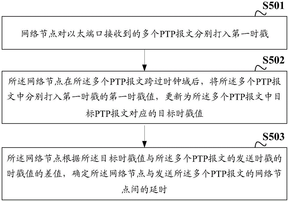
基于上述实施例,如图5所示,本申请实施例提供了一种打戳处理方法,具体步骤包括:Based on the above embodiment, as shown in FIG. 5, the embodiment of the present application provides a stamping processing method, and the specific steps include:
S501:网络节点对以太端口接收到的多个PTP报文分别打入第一时戳。其中,所述以太端口具有多个lane,所述多个PTP报文为所述网络节点通过所述多个lane接收的。S501: The network node adds first time stamps to the multiple PTP packets received by the Ethernet port. Wherein, the Ethernet port has multiple lanes, and the multiple PTP messages are received by the network node through the multiple lanes.
S502:所述网络节点在所述多个PTP报文跨过时钟域后,将所述多个PTP报文中分别打入第一时戳的第一时戳值,更新为所述多个PTP报文中目标PTP报文对应的目标时戳值。其中,所述目标PTP报文为所述多个lane中目标lane接收的PTP报文,所述目标lane为延时最短的lane或延时最长的lane;S502: After the multiple PTP messages cross the clock domain, the network node updates the first time stamp values respectively entered into the first time stamps in the multiple PTP messages to the multiple PTP messages The target timestamp value corresponding to the target PTP packet in the packet. Wherein, the target PTP message is a PTP message received by the target lane in the plurality of lanes, and the target lane is the lane with the shortest delay or the lane with the longest delay;
S503:所述网络节点根据所述目标时戳值与所述多个PTP报文的发送时戳的时戳值的差值,确定所述网络节点与发送所述多个PTP报文的网络节点间的延时。S503: The network node determines the network node and the network node sending the multiple PTP messages according to the difference between the target time stamp value and the time stamp value of the sending time stamps of the multiple PTP messages delay between.
基于相同的构思,图6为本申请提供的一种网络节点600,包括:处理器601和收发器602;Based on the same idea, FIG. 6 shows a
处理器601通过收发器602在以太端口接收到的多个PTP报文写入所述以太端口的deskew fifo之前,对所述多个PTP报文分别打入第一时戳;其中,所述以太端口具有多个lane,所述多个PTP报文为所述网络节点通过所述多个lane接收的;Before the multiple PTP messages received by the Ethernet port are written into the deskew fifo of the Ethernet port through the
所述处理器601,还用于在所述deskew fifo输出所述多个PTP时,将所述多个PTP报文中分别打入第一时戳的第一时戳值,更新为所述多个PTP报文中目标PTP报文对应的目标时戳值;其中,所述目标PTP报文为所述多个lane中目标lane接收的PTP报文,所述目标lane为延时最短的lane或延时最长的lane;The
所述处理器601,还用于根据所述目标时戳值与所述多个PTP报文的发送时戳的时戳值的差值,确定所述网络节点与发送所述多个PTP报文的网络节点间的延时。。The
可选的,所述处理器601,具体用于通过收发器602在以太端口接收到的多个PTP报文写入所述以太端口的deskew fifo之前,对所述多个PTP报文的第一个bit分别打入第一时戳。Optionally, the
可选的,所述处理器601,具体用于通过收发器602在以太端口接收到的多个PTP报文写入所述以太端口的deskew fifo之前,对所述多个PTP报文的设定bit分别打入第一时戳;基于所述多个PTP报文分别对应所述设定bit与第一个bit的距离,确定所述多个PTP报文分别对应第一个bit至设定bit的第一传输时长;将所述多个PTP报文中分别打入第一时戳的第一时戳值,校正为所述第一时戳值与所述PTP报文对应的第一传输时长的差值。Optionally, the
可选的,所述处理器601,具体用于按照测量周期,根据当前测量周期以太端口的多个lane分别对应的打戳时间,通过收发器602在所述以太端口接收的多个PTP报文写入所述以太端口的deskew fifo之前,对所述多个PTP报文分别打入第一时戳;基于所述多个PTP报文分别对应打入第一时戳的目标bit与第一个bit的距离,确定所述多个PTP报文分别对应第一个bit至打入第一时戳的目标bit的第二传输时长;将所述多个PTP报文中分别打入第一时戳的第一时戳值,校正为所述第一时戳值与所述PTP报文对应的第二传输时长的差值。Optionally, the
可选的,所述处理器601,具体用于根据所述多个PTP报文中分别打入第一时戳的第一时戳值,与接收所述PTP报文的lane相对于目标lane的延时差异的和,对所述多个PTP报文中分别打入的第一时戳的第一时戳值进行更新;其中,多个lane分别相对于目标lane的延时差异,是根据在写入所述以太端口的deskew fifo之前,对所述目标lane接收的PTP报文的设定bit打入第二时戳的第二时戳值,分别与所述多个lane接收的PTP报文的设定bit打入第二时戳的第二时戳值的差确定的。Optionally, the
可选的,所述处理器601,具体用于在所述以太端口建链时,将对所述以太端口接收的多个PTP报文分别打入的第三时戳的第三时戳值中,最大时戳值的目标PTP报文所对应的lane或最小时戳值的目标PTP报文所述对应的lane,确定为目标lane。Optionally, the
基于相同的构思,本申请实施例还提供了一种网络节点。Based on the same idea, the embodiment of the present application also provides a network node.
如图7所示,网络节点700包括存储器701、处理器702和收发器703。存储器701、处理器702和收发器703通过总线链接。存储器701用于存储计算机执行指令,当网络节点700运行时,处理器702通过收发器703执行存储器701中存储的计算机执行指令,以使网络节点700实现上述任一项打戳处理方法,可参考上文及其附图的相关描述,在此不做赘述。As shown in FIG. 7 , a
本申请实施例提供了一种计算机存储介质,存储有计算机程序,该计算机程序包括用于执行上述方法实施例描述的打戳处理方法的指令。An embodiment of the present application provides a computer storage medium storing a computer program, the computer program including instructions for executing the stamping processing method described in the above method embodiment.
本申请实施例提供了一种包含指令的计算机程序产品,当其在网络节点上运行时,使得网络节点实现上述方法实施例描述的打戳处理方法。An embodiment of the present application provides a computer program product containing instructions, which, when run on a network node, enables the network node to implement the stamping processing method described in the foregoing method embodiments.
本申请实施例提供了一种芯片,所述芯片与存储器相连,用于读取并执行所述存储器中存储的软件程序,以实现上述方法实施例描述的打戳处理方法。An embodiment of the present application provides a chip, the chip is connected to a memory, and is used to read and execute a software program stored in the memory, so as to implement the stamping processing method described in the above method embodiment.
本领域内的技术人员应明白,本申请的实施例可提供为方法、系统、或计算机程序产品。因此,本申请可采用完全硬件实施例、完全软件实施例、或结合软件和硬件方面的实施例的形式。而且,本申请可采用在一个或多个其中包含有计算机可用程序代码的计算机可用存储介质(包括但不限于磁盘存储器、CD-ROM、光学存储器等)上实施的计算机程序产品的形式。Those skilled in the art should understand that the embodiments of the present application may be provided as methods, systems, or computer program products. Accordingly, the present application may take the form of an entirely hardware embodiment, an entirely software embodiment, or an embodiment combining software and hardware aspects. Furthermore, the present application may take the form of a computer program product embodied on one or more computer-usable storage media (including but not limited to disk storage, CD-ROM, optical storage, etc.) having computer-usable program code embodied therein.
本申请是参照根据本申请实施例的方法、设备(系统)、和计算机程序产品的流程图和/或方框图来描述的。应理解可由计算机程序指令实现流程图和/或方框图中的每一流程和/或方框、以及流程图和/或方框图中的流程和/或方框的结合。可提供这些计算机程序指令到通用计算机、专用计算机、嵌入式处理机或其他可编程数据处理设备的处理器以产生一个机器,使得通过计算机或其他可编程数据处理设备的处理器执行的指令产生用于实现在流程图一个流程或多个流程和/或方框图一个方框或多个方框中指定的功能的装置。The present application is described with reference to flowcharts and/or block diagrams of methods, apparatus (systems), and computer program products according to embodiments of the present application. It should be understood that each procedure and/or block in the flowchart and/or block diagram, and a combination of procedures and/or blocks in the flowchart and/or block diagram can be realized by computer program instructions. These computer program instructions may be provided to a general purpose computer, special purpose computer, embedded processor, or processor of other programmable data processing equipment to produce a machine such that the instructions executed by the processor of the computer or other programmable data processing equipment produce a An apparatus for realizing the functions specified in one or more procedures of the flowchart and/or one or more blocks of the block diagram.
这些计算机程序指令也可存储在能引导计算机或其他可编程数据处理设备以特定方式工作的计算机可读存储器中,使得存储在该计算机可读存储器中的指令产生包括指令装置的制造品,该指令装置实现在流程图一个流程或多个流程和/或方框图一个方框或多个方框中指定的功能。These computer program instructions may also be stored in a computer-readable memory capable of directing a computer or other programmable data processing apparatus to operate in a specific manner, such that the instructions stored in the computer-readable memory produce an article of manufacture comprising instruction means, the instructions The device realizes the function specified in one or more procedures of the flowchart and/or one or more blocks of the block diagram.
这些计算机程序指令也可装载到计算机或其他可编程数据处理设备上,使得在计算机或其他可编程设备上执行一系列操作步骤以产生计算机实现的处理,从而在计算机或其他可编程设备上执行的指令提供用于实现在流程图一个流程或多个流程和/或方框图一个方框或多个方框中指定的功能的步骤。These computer program instructions can also be loaded onto a computer or other programmable data processing device, causing a series of operational steps to be performed on the computer or other programmable device to produce a computer-implemented process, thereby The instructions provide steps for implementing the functions specified in the flow chart or blocks of the flowchart and/or the block or blocks of the block diagrams.
尽管已描述了本申请的优选实施例,但本领域内的技术人员一旦得知了基本创造性概念,则可对这些实施例作出另外的变更和修改。所以,所附权利要求意欲解释为包括优选实施例以及落入本申请范围的所有变更和修改。While preferred embodiments of the present application have been described, additional changes and modifications to these embodiments can be made by those skilled in the art once the basic inventive concept is appreciated. Therefore, the appended claims are intended to be construed to cover the preferred embodiment and all changes and modifications which fall within the scope of the application.
显然,本领域的技术人员可以对本申请实施例进行各种改动和变型而不脱离本申请实施例的精神和范围。这样,倘若本申请实施例的这些修改和变型属于本申请权利要求及其等同技术的范围之内,则本申请也意图包含这些改动和变型在内。Apparently, those skilled in the art can make various changes and modifications to the embodiments of the present application without departing from the spirit and scope of the embodiments of the present application. In this way, if the modifications and variations of the embodiments of the present application fall within the scope of the claims of the present application and their equivalent technologies, the present application also intends to include these modifications and variations.
Claims (15)
Applications Claiming Priority (1)
| Application Number | Priority Date | Filing Date | Title |
|---|---|---|---|
| PCT/CN2018/123226 WO2020132834A1 (en) | 2018-12-24 | 2018-12-24 | Method and device for stamping processing |
Publications (2)
| Publication Number | Publication Date |
|---|---|
| CN113228564A CN113228564A (en) | 2021-08-06 |
| CN113228564B true CN113228564B (en) | 2022-12-30 |
Family
ID=71129469
Family Applications (1)
| Application Number | Title | Priority Date | Filing Date |
|---|---|---|---|
| CN201880100455.7A Active CN113228564B (en) | 2018-12-24 | 2018-12-24 | Stamping processing method and device |
Country Status (2)
| Country | Link |
|---|---|
| CN (1) | CN113228564B (en) |
| WO (1) | WO2020132834A1 (en) |
Families Citing this family (2)
| Publication number | Priority date | Publication date | Assignee | Title |
|---|---|---|---|---|
| CN114221733B (en) * | 2021-12-27 | 2023-11-07 | 深圳市紫光同创电子有限公司 | Error compensation method for synchronizing time stamps |
| CN116318511A (en) * | 2023-03-17 | 2023-06-23 | 武汉飞思灵微电子技术有限公司 | A method and device for determining a sending time stamp |
Citations (4)
| Publication number | Priority date | Publication date | Assignee | Title |
|---|---|---|---|---|
| CN103580846A (en) * | 2013-08-23 | 2014-02-12 | 北京东土科技股份有限公司 | Method and system for transmitting precision clock message by spanning non-1588 network |
| CN104113517A (en) * | 2013-04-22 | 2014-10-22 | 华为技术有限公司 | Timestamp generation method, device and system |
| CN106788842A (en) * | 2016-11-30 | 2017-05-31 | 瑞斯康达科技发展股份有限公司 | The processing method and SOC of a kind of PTP messages |
| CN108880723A (en) * | 2017-05-16 | 2018-11-23 | 深圳市中兴软件有限责任公司 | A kind of method and apparatus that clock is synchronous |
Family Cites Families (4)
| Publication number | Priority date | Publication date | Assignee | Title |
|---|---|---|---|---|
| US8675689B2 (en) * | 2011-02-15 | 2014-03-18 | General Electric Company | Method of time synchronization of free running nodes in an avionics network |
| JP2017098694A (en) * | 2015-11-20 | 2017-06-01 | 富士通株式会社 | Communication apparatus and time synchronizing method therefor |
| US9973292B2 (en) * | 2016-04-01 | 2018-05-15 | Khalifa University Of Science, Technology And Research | Methods and systems for estimating offset and skew using linear programming |
| US10742782B2 (en) * | 2017-05-26 | 2020-08-11 | Xilinx, Inc. | Time stamping network device |
-
2018
- 2018-12-24 WO PCT/CN2018/123226 patent/WO2020132834A1/en not_active Ceased
- 2018-12-24 CN CN201880100455.7A patent/CN113228564B/en active Active
Patent Citations (4)
| Publication number | Priority date | Publication date | Assignee | Title |
|---|---|---|---|---|
| CN104113517A (en) * | 2013-04-22 | 2014-10-22 | 华为技术有限公司 | Timestamp generation method, device and system |
| CN103580846A (en) * | 2013-08-23 | 2014-02-12 | 北京东土科技股份有限公司 | Method and system for transmitting precision clock message by spanning non-1588 network |
| CN106788842A (en) * | 2016-11-30 | 2017-05-31 | 瑞斯康达科技发展股份有限公司 | The processing method and SOC of a kind of PTP messages |
| CN108880723A (en) * | 2017-05-16 | 2018-11-23 | 深圳市中兴软件有限责任公司 | A kind of method and apparatus that clock is synchronous |
Non-Patent Citations (1)
| Title |
|---|
| 确定性工业以太网的研究;林涛等;《微计算机信息》;20050915(第09期);全文 * |
Also Published As
| Publication number | Publication date |
|---|---|
| CN113228564A (en) | 2021-08-06 |
| WO2020132834A1 (en) | 2020-07-02 |
Similar Documents
| Publication | Publication Date | Title |
|---|---|---|
| US11223439B1 (en) | Maintaining a time of day in a physical layer circuit including compensating for drift away from a grandmaster time | |
| US8370675B2 (en) | Precise clock synchronization | |
| US10931391B2 (en) | One-step time stamping of synchronization packets for networked devices | |
| CN101595669B (en) | Method and device for exchanging information for facilitating synchronization of time network | |
| US8879586B2 (en) | Inband timestamping | |
| KR102031268B1 (en) | Method and apparatus for communicating time information between time-aware devices | |
| US8451867B2 (en) | Network time protocol precision timestamping service | |
| JP5518191B2 (en) | Method and system for optical transmission network carrying time synchronization protocol | |
| WO2014173267A1 (en) | Timestamp generating method, device and system | |
| CN112166565B (en) | Timing synchronization of cable networks | |
| US11349587B2 (en) | Generating a timestamp | |
| US11757614B2 (en) | Accurate timestamp correction | |
| US20220029778A1 (en) | System and method for synchronizing nodes in a network device | |
| JP6351889B1 (en) | Communication system and slave device | |
| WO2021077289A1 (en) | Synchronization method and device | |
| CN114138054A (en) | A time stamp acquisition method, device, electronic device and storage medium | |
| CN113228564B (en) | Stamping processing method and device | |
| CN112583509B (en) | Method and device for acquiring time stamp of data stream, storage medium and electronic device | |
| CN112751641B (en) | A TSN network time synchronization method, device and storage medium | |
| CN112039621B (en) | A time synchronization method and system | |
| CN107888315A (en) | A kind of method for synchronizing time | |
| WO2024120469A1 (en) | Clock synchronization method and apparatus, device, storage medium, and computer program | |
| WO2023197835A1 (en) | Clock synchronization method and related device | |
| US20250055587A1 (en) | Providing arbitrarily long timer from shorter underlying hardware counter | |
| JP7625384B2 (en) | Communication device, communication method, and program |
Legal Events
| Date | Code | Title | Description |
|---|---|---|---|
| PB01 | Publication | ||
| PB01 | Publication | ||
| SE01 | Entry into force of request for substantive examination | ||
| SE01 | Entry into force of request for substantive examination | ||
| GR01 | Patent grant | ||
| GR01 | Patent grant |