CN113006133B - Construction method of middle plate hole suitable for assembly type station - Google Patents
Construction method of middle plate hole suitable for assembly type station Download PDFInfo
- Publication number
- CN113006133B CN113006133B CN202110134441.0A CN202110134441A CN113006133B CN 113006133 B CN113006133 B CN 113006133B CN 202110134441 A CN202110134441 A CN 202110134441A CN 113006133 B CN113006133 B CN 113006133B
- Authority
- CN
- China
- Prior art keywords
- prefabricated
- hole
- middle plate
- initial hole
- initial
- Prior art date
- Legal status (The legal status is an assumption and is not a legal conclusion. Google has not performed a legal analysis and makes no representation as to the accuracy of the status listed.)
- Active
Links
Images


Classifications
-
- E—FIXED CONSTRUCTIONS
- E02—HYDRAULIC ENGINEERING; FOUNDATIONS; SOIL SHIFTING
- E02D—FOUNDATIONS; EXCAVATIONS; EMBANKMENTS; UNDERGROUND OR UNDERWATER STRUCTURES
- E02D29/00—Independent underground or underwater structures; Retaining walls
- E02D29/04—Making large underground spaces, e.g. for underground plants, e.g. stations of underground railways; Construction or layout thereof
Abstract
The invention relates to the technical field of fabricated stations, and discloses a construction method of a middle plate hole suitable for a fabricated station, which comprises the following steps of laying a prefabricated bottom plate block at a position corresponding to the preset middle plate hole; assembling prefabricated side lower blocks on the left side and the right side of the prefabricated bottom plate block respectively; assembling prefabricated air duct blocks at the upper ends of the two prefabricated side lower blocks respectively, wherein the two prefabricated air duct blocks are arranged at intervals; the two prefabricated air duct blocks on the left side and the right side and the prefabricated middle plate blocks on the front side and the rear side are enclosed to form an initial hole; the area of the initial hole is larger than that of the preset middle plate hole, the middle plate hole construction method applicable to the assembly type station has the advantages of being flexible in construction operation, high in construction speed, short in site construction period, labor-saving and the like by assembling the middle plate hole through the prefabricated part, and the problem that the hole is prone to deformation when the station is not closed is solved by arranging the support frame in the hole to support the initial hole after the initial hole is assembled.
Description
Technical Field
The invention relates to the technical field of assembly type stations, in particular to a construction method of a middle plate hole suitable for an assembly type station.
Background
At present, the construction of a middle plate hole is generally erected through a scaffold, a template is erected, and concrete is poured and formed after reinforcing steel bars are bound. Because scaffolds and templates are not erected during construction of middle plate holes of the prefabricated station, the station is not closed during construction of the middle plate holes, and the whole stress is not applied, so that the effective transmission of horizontal force is difficult to ensure; in addition, the prefabricated station is assembled section by section, the requirements for modularization and streamline on construction equipment are met, and the traditional middle plate hole construction method is not suitable for the requirements of the prefabricated station.
Disclosure of Invention
In view of the above, the present invention is directed to a method for constructing a middle plate hole of an assembly station.
In order to solve the above technical problems, the present invention provides a construction method of a middle plate hole suitable for an assembly type station, comprising the steps of,
laying a prefabricated bottom plate block at a position corresponding to a hole of a preset middle plate;
respectively assembling prefabricated side lower blocks on the left side and the right side of the prefabricated bottom plate block;
assembling prefabricated air duct blocks at the upper ends of the two prefabricated side lower blocks respectively, wherein the two prefabricated air duct blocks are arranged at intervals;
the two prefabricated air duct blocks on the left side and the right side and the prefabricated middle plate blocks on the front side and the rear side are enclosed to form an initial hole; the area of the initial hole is larger than that of the preset middle plate hole;
assembling a support frame in the initial hole, wherein the left end and the right end of the support frame are detachably connected with the prefabricated air duct block, and the lower end of the support frame is detachably connected with the prefabricated bottom plate block;
and laying templates serving as concrete bottom molds at the periphery of the initial holes along the upper ends of the support frames, binding reinforcing mesh, and pouring concrete to form the preset middle plate holes.
Optionally, still include before the upper end of support frame is followed initial hole is laid the sideboard all around as the concrete die block that first reinforcing bar frame is installed to the direction before the border of initial hole, second reinforcing bar frame is installed to the left and right sides at the border of initial hole, the reinforcing bar net respectively with first reinforcing bar frame with second reinforcing bar frame fixed connection.
Optionally, the prefabricated middle plates on the front side and the rear side of the initial hole are both prefabricated middle plates, two prefabricated middle plates are respectively provided with a first reinforcing steel bar connector, and the first reinforcing steel bar frame is arranged between the two first reinforcing steel bar connectors on the front side and the rear side of the initial hole.
Optionally, second reinforcing steel bar connectors are respectively arranged on the prefabricated air duct blocks on the left side and the right side of the initial hole, and the second reinforcing steel bar frame is arranged between the two second reinforcing steel bar connectors on the left side and the right side of the initial hole.
Optionally, the support frame includes girder, secondary beam and post roof beam, and is a plurality of the secondary beam is followed the fore-and-aft direction of initial hole sets up, and is a plurality of the girder is followed the left and right sides direction setting of initial hole, the girder fixed set up in the lower extreme of secondary beam, post roof beam vertical set up in the lower extreme of girder, the lower extreme of post roof beam with the connection can be dismantled to the prefabricated bottom plate piece.
Optionally, a first pre-buried connecting piece is arranged on the prefabricated bottom plate block, and a first pre-buried connected piece connected with the first pre-buried connecting piece is arranged at the lower end of the column beam of the support frame.
Optionally, a second pre-buried connecting piece is arranged on the prefabricated air duct block, and second pre-buried connected pieces connected with the second pre-buried connecting piece are arranged at the left end and the right end of the secondary beam of the support frame.
Optionally, the main beam, the secondary beam and the column beam are all formed by assembling and welding profile steels.
Compared with the prior art, the construction method of the middle plate hole suitable for the assembly type station has the beneficial effects that:
the construction method of the middle plate hole suitable for the assembly type station has the advantages that the middle plate hole is assembled by adopting the prefabricated parts, the construction operation is flexible, the construction speed is high, the field construction period is short, the industrialization degree is high, the field operation amount is reduced, the labor force is saved and the like, and the support frame is arranged in the hole for supporting after the initial hole assembly is completed, so that the problems that the hole is easy to deform and the force transmission is discontinuous when the station is not closed are solved.
Drawings
Fig. 1 is a schematic structural diagram of an initial hole of a middle plate hole suitable for an assembly station according to an embodiment of the present invention;
fig. 2 is a schematic structural view illustrating a support frame for a middle plate hole of an assembly station according to an embodiment of the present invention disposed in an initial hole;
fig. 3 is a schematic structural view illustrating a first reinforcing frame and a second reinforcing frame installed in an initial hole of a middle plate hole of an assembly station according to an embodiment of the present invention;
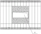
fig. 4 is a schematic structural diagram of a preset middle plate hole suitable for a middle plate hole of an assembly station according to an embodiment of the present invention.
In the figure, 1, a prefabricated bottom plate block, 2, a prefabricated lateral lower block, 3, a prefabricated air duct block, 4, a prefabricated middle plate block, 5, an initial hole, 6, a preset middle plate hole, 7, a support frame, 71, a main beam, 72, a secondary beam, 73, a column beam, 8, a first reinforcing steel bar frame, 9, a second reinforcing steel bar frame, 10, a first pre-embedded connecting piece, 11 and a second pre-embedded connecting piece.
Detailed Description
It should be noted that the embodiments and features of the embodiments of the present invention may be combined with each other without conflict.
In addition, the following description will be briefly made with reference to the orientation: the following directional or positional relationships, as referred to with reference to "front", "rear", "upper", "lower", "left", "right", etc., of each structural member, refer to the orientation or positional relationship shown in the drawings; these positional relationships are merely for convenience and simplicity of description and do not indicate or imply that the device referred to must have a particular orientation, be constructed and operated in a particular orientation and therefore should not be construed as limiting the invention.
If there is a description of "first", "second", etc. in an embodiment of the present invention, the description of "first", "second", etc. is for descriptive purposes only and is not to be construed as indicating or implying relative importance or implicitly indicating the number of technical features indicated.
In order to make the aforementioned objects, features and advantages of the present invention comprehensible, embodiments accompanied with figures are described in detail below.
As shown in fig. 1 to 4, a construction method of a middle plate hole suitable for an assembly station according to a preferred embodiment of the present invention includes the following steps,
laying a prefabricated bottom plate block 1 at a position corresponding to the preset middle plate hole 6;
in this embodiment, the prefabricated bottom plate block is formed for concrete is pour in advance, and pre-buried connecting piece is pre-buried on the prefabricated bottom plate block to be connected with the support frame.
Assembling prefabricated side lower blocks 2 on the left side and the right side of the prefabricated bottom plate block 1 respectively;
assembling prefabricated air duct blocks 3 at the upper ends of the two prefabricated side lower blocks 2 respectively, wherein the two prefabricated air duct blocks 3 are arranged at intervals; in above-mentioned prefabricated section preparation process, all be provided with the hollow hole on prefabricated bottom plate piece, prefabricated side lower block and the prefabricated wind channel piece, under the condition that does not influence its structural strength, reduce the dead weight, the hoist and mount of being convenient for.
Through assembling prefabricated side lower piece and ear piece in proper order at prefabricated bottom plate piece both sides, the equipment forms portal ring roof beam, leaves the clearance between the ear piece, and ear piece and well slab enclose closes and form initial hole.
The two prefabricated air duct blocks 3 on the left side and the right side and the prefabricated middle plate blocks 4 on the front side and the rear side are enclosed to form an initial hole 5; the area of the initial hole 5 is larger than that of the preset middle plate hole 6;
because the shape of the middle plate hole is more, the middle plate hole has a staircase hole, a T-shaped stair hole, an equipment hole and the like, if the air duct blocks are prefabricated in shape in advance, the assembly is complex, and the designed hole size is difficult to achieve, therefore, in the embodiment, the air duct blocks are prefabricated in a unified mode, the initial hole is formed in a surrounding mode in a station, then secondary construction is carried out according to the design requirements of the hole, concrete is cast in place, the engineering quantity is small, and the design standard of the better hole is achieved.
Assembling a support frame 7 in the initial hole 5, wherein the left end and the right end of the support frame 7 are detachably connected with the prefabricated air duct block 3, and the lower end of the support frame 7 is detachably connected with the prefabricated bottom plate block 1; therefore, the support frame can load the earthwork pressure from the left and rear sides of the portal ring beam and in the vertical direction in the initial hole, the deformation phenomenon of the initial hole is avoided, and the stable and reliable construction of the preset middle plate hole is ensured.
And (3) paving templates around the initial hole 5 at the upper end of the support frame 7 to serve as a concrete bottom die, binding a reinforcing mesh, pouring concrete to form the preset middle plate hole 6, generally, in a station construction site, casting concrete hole side plates around the escalator with the largest hole size of 4.2 multiplied by 11 multiplied by 0.5m, and closing to form a ring. After the middle plate hole is preset and pouring molding is carried out, when reliable strength and connection between concrete and prefabricated block concrete around are guaranteed, the supporting frame is detached at selected time, and the middle plate hole is convenient to pass.
The upper end of the supporting frame 7 is arranged along the periphery of the initial hole 5 and is further arranged before being used as a concrete bottom die, a first reinforcing steel bar frame 8 is arranged in the front-back direction of the edge of the initial hole 5, second reinforcing steel bar frames 9 are arranged on the left side and the right side of the edge of the initial hole 5, the reinforcing steel bar nets are fixedly connected with the first reinforcing steel bar frame 8 and the second reinforcing steel bar frames 9 respectively and are mutually connected with the first reinforcing steel bar frame and the second reinforcing steel bar frames through the reinforcing steel bar nets, concrete is poured, the poured edge plates and the edge of the initial hole can be mutually connected, the connection strength of the poured edge plates and the edge of the initial hole can be improved, and the integrally poured connection effect can be achieved.
The prefabricated middle plates 4 on the front side and the rear side of the initial hole 5 are prefabricated middle plates, first steel bar connectors are arranged on the two prefabricated middle plates respectively, and the first steel bar frames 8 are arranged between the two first steel bar connectors on the front side and the rear side of the initial hole 5.
Second reinforcing steel bar connectors are respectively arranged on the prefabricated air duct blocks 3 on the left side and the right side of the initial hole 5, and the second reinforcing steel bar frames 9 are arranged between the two second reinforcing steel bar connectors on the left side and the right side of the initial hole 5.
In this embodiment, the first and second steel frames are two steel bars disposed at the side of the initial hole, and two layers are disposed in the vertical direction, and when the steel bar mesh is bound, the steel bar mesh is connected to the steel bar frame. Through pre-buried prefabricated bar connector on the prefabricated middle plate piece and on the prefabricated wind channel piece, the reinforcing bar frame of easy to assemble, and through the bar connector, the reinforcing bar frame can carry out the connection with the reinforcing bar of concrete prefabricated section, makes its whole connection shaping.
The prefabricated bottom plate block 1 is provided with a first embedded connecting piece 10, the lower end of the column beam 73 of the support frame 7 is provided with a first embedded connected piece connected with the first embedded connecting piece 10, and the prefabricated bottom plate block and the support frame can be conveniently connected and detached by arranging the first embedded connecting piece and the first embedded connected piece. The first embedded connecting piece is selected from an embedded template, embedded section steel, embedded steel bars, embedded grouting sleeves or embedded bolt hole sites; the first embedded connected piece is selected from embedded templates, embedded section steel, embedded steel bars, embedded grouting sleeves or embedded bolt hole positions. In this embodiment, the first pre-buried connecting member 11 is a pre-buried grouting sleeve, and the first pre-buried connected member 231 is a pre-buried bolt hole site.
The prefabricated air duct block 3 is provided with a second embedded connecting piece 11, the left end and the right end of the secondary beam 72 of the support frame 7 are provided with second embedded connected pieces connected with the second embedded connecting pieces 11, the connection and the disassembly between the prefabricated bottom plate block and the support frame are facilitated by arranging the second embedded connecting pieces and the second embedded connected pieces, and the second embedded connecting pieces are selected from embedded templates, embedded section steel, embedded steel bars, embedded grouting sleeves or embedded bolt hole positions; the second embedded connected piece is selected from embedded templates, embedded section steel, embedded steel bars, embedded grouting sleeves or embedded bolt hole sites. In this embodiment, the second embedded connecting member is an embedded template, and the second embedded connected member is an embedded template.
The main beam 71, the secondary beam 72 and the column beam 73 are all formed by assembling and welding section steel and have enough structural strength.
The invention relates to a middle plate holing processing method which adopts a whole set of steel structure as a temporary inner support and also serves as a template system and is matched with a cast-in-place-prefabricated block combined stress permanent structure connected by steel bars. The main implementation process comprises the following steps: when the precast block of the middle plate opening ring is manufactured, the anchor bolt sleeves are reserved at corresponding positions on the precast bottom plate blocks at the front and rear two ring (generally No. 1 ring and No. 6 ring) ends of a hole, the straight thread connecting sleeves are reserved at corresponding positions on the 12 (generally 12) precast air duct blocks at two sides, and the (generally 6) 6 ring corresponding precast bottom plate blocks, the precast side lower blocks and the precast air duct blocks (the precast middle plate blocks are not assembled) are assembled by flowing water; 3. installing the section steel column beams, the column supports, the section steel main beams, the section steel secondary beams and the wood templates in time after the assembly is finished; 4. binding and installing the steel bars of the cast-in-place plate around the initial hole, and connecting the steel bars with the precast block steel bar frame through the pre-embedded straight thread connecting sleeve; 5. pouring concrete around the initial hole; 6. and (4) after the concrete reaches the designed strength, sequentially removing the wood template, the section steel secondary beam, the section steel main beam, the inter-column support and the section steel column beam at certain time. The modularization requirement of a prefabricated station scheme is met; the requirement of flow line production of a prefabricated station scheme is met; and the construction efficiency of the station is improved.
To sum up, compared with the prior art, the construction method of the middle plate hole suitable for the assembly type station has the beneficial effects that: the construction method of the middle plate hole suitable for the assembly type station, provided by the embodiment of the invention, has the advantages of flexible construction operation, high construction speed, short field construction period, high industrialization degree, field operation amount reduction, labor saving and the like by assembling the middle plate hole by adopting the prefabricated part, and the problem that the hole is easy to deform when the station is not closed is solved by arranging the support frame in the hole for supporting after the initial hole assembly is finished.
The above description is only a preferred embodiment of the present invention, and it should be noted that, for those skilled in the art, various modifications and substitutions can be made without departing from the technical principle of the present invention, and these modifications and substitutions should also be regarded as the protection scope of the present invention.
Claims (7)
1. A construction method of a middle plate hole suitable for an assembly type station is characterized by comprising the following steps,
laying a prefabricated bottom plate block (1) at a position corresponding to the preset middle plate hole (6);
assembling prefabricated side lower blocks (2) on the left side and the right side of the prefabricated bottom plate block (1) respectively;
prefabricated air duct blocks (3) are respectively assembled at the upper ends of the two prefabricated side lower blocks (2), and the two prefabricated air duct blocks (3) are arranged at intervals;
the two prefabricated air duct blocks (3) on the left side and the right side and the prefabricated middle plate blocks (4) on the front side and the rear side are enclosed to form an initial hole (5); the area of the initial hole (5) is larger than that of the preset middle plate hole (6);
assembling a support frame (7) in the initial hole (5), wherein the left end and the right end of the support frame (7) are detachably connected with the prefabricated air duct block (3), and the lower end of the support frame (7) is detachably connected with the prefabricated bottom plate block (1);
laying templates serving as concrete bottom molds at the upper ends of the support frames (7) along the periphery of the initial holes (5), binding reinforcing mesh, and pouring concrete to form the preset middle plate holes (6); the upper end of support frame (7) is followed initial hole (5) is laid the sideboard all around and is still included as the concrete die block before initial hole (5) first reinforcing bar frame (8) of installation in the preceding rear direction in border of initial hole (5) second reinforcing bar frame (9) are installed to the left and right sides at the border of initial hole (5), the reinforcing bar net respectively with first reinforcing bar frame (8) with second reinforcing bar frame (9) fixed connection.
2. The construction method of a middle plate hole suitable for a fabricated station as claimed in claim 1, wherein the prefabricated middle plates (4) at the front and rear sides of the initial hole (5) are both prefabricated middle plates, first reinforcing bar connectors are respectively provided on the two prefabricated middle plates, and the first reinforcing bar frame (8) is disposed between the two first reinforcing bar connectors at the front and rear sides of the initial hole (5).
3. The construction method of the middle plate hole suitable for the fabricated station as claimed in claim 1, wherein second reinforcing bar connectors are respectively provided on the prefabricated air duct blocks (3) at the left and right sides of the initial hole (5), and the second reinforcing bar frame (9) is disposed between the two second reinforcing bar connectors at the left and right sides of the initial hole (5).
4. The middle plate hole construction method applicable to an assembly type station as claimed in claim 1, wherein the support frame (7) comprises a main beam (71), a secondary beam (72) and a column beam (73), a plurality of the secondary beams (72) are arranged along the front-rear direction of the initial hole (5), a plurality of the main beams (71) are arranged along the left-right direction of the initial hole (5), the main beam (71) is fixedly arranged at the lower end of the secondary beam (72), the column beam (73) is vertically arranged at the lower end of the main beam (71), and the lower end of the column beam (73) is detachably connected with the prefabricated bottom plate block (1).
5. The middle plate hole construction method suitable for the fabricated station as claimed in claim 4, wherein a first pre-buried connector (10) is provided on the prefabricated bottom plate block (1), and a first pre-buried connected member connected to the first pre-buried connector (10) is provided at the lower end of the column beam (73) of the support frame (7).
6. The construction method of the middle plate hole suitable for the fabricated station as claimed in claim 4, wherein a second pre-buried connector (11) is provided on the prefabricated air duct block (3), and second pre-buried connectors connected to the second pre-buried connector (11) are provided at both left and right ends of the secondary beam (72) of the support frame (7).
7. The middle plate hole construction method suitable for the assembly type station as claimed in claim 4, wherein the main beam (71), the secondary beam (72) and the column beam (73) are all formed by assembling and welding section steel.
Priority Applications (1)
| Application Number | Priority Date | Filing Date | Title |
|---|---|---|---|
| CN202110134441.0A CN113006133B (en) | 2021-01-29 | 2021-01-29 | Construction method of middle plate hole suitable for assembly type station |
Applications Claiming Priority (1)
| Application Number | Priority Date | Filing Date | Title |
|---|---|---|---|
| CN202110134441.0A CN113006133B (en) | 2021-01-29 | 2021-01-29 | Construction method of middle plate hole suitable for assembly type station |
Publications (2)
| Publication Number | Publication Date |
|---|---|
| CN113006133A CN113006133A (en) | 2021-06-22 |
| CN113006133B true CN113006133B (en) | 2022-10-14 |
Family
ID=76384714
Family Applications (1)
| Application Number | Title | Priority Date | Filing Date |
|---|---|---|---|
| CN202110134441.0A Active CN113006133B (en) | 2021-01-29 | 2021-01-29 | Construction method of middle plate hole suitable for assembly type station |
Country Status (1)
| Country | Link |
|---|---|
| CN (1) | CN113006133B (en) |
Citations (5)
| Publication number | Priority date | Publication date | Assignee | Title |
|---|---|---|---|---|
| CN105064398A (en) * | 2015-08-19 | 2015-11-18 | 中国能源建设集团天津电力建设有限公司 | One-time overall pouring construction method for nuclear powder single-hole GD gallery |
| CN106869172A (en) * | 2017-04-01 | 2017-06-20 | 中交第二航务工程局有限公司 | In-situ deposited prefabricated split-mounting type subway underground station construction method |
| CN107558491A (en) * | 2017-07-13 | 2018-01-09 | 浙江永联建设工程股份有限公司 | A kind of underground pipe gallery and its construction method |
| CN111456088A (en) * | 2020-05-12 | 2020-07-28 | 中交哈尔滨地铁投资建设有限公司 | Subway station with overlapped assembly type structure and assembly construction method |
| CN112012239A (en) * | 2020-08-11 | 2020-12-01 | 广州地铁设计研究院股份有限公司 | Assembling structure and assembling method for prefabricated middle plate at hole of station |
-
2021
- 2021-01-29 CN CN202110134441.0A patent/CN113006133B/en active Active
Patent Citations (5)
| Publication number | Priority date | Publication date | Assignee | Title |
|---|---|---|---|---|
| CN105064398A (en) * | 2015-08-19 | 2015-11-18 | 中国能源建设集团天津电力建设有限公司 | One-time overall pouring construction method for nuclear powder single-hole GD gallery |
| CN106869172A (en) * | 2017-04-01 | 2017-06-20 | 中交第二航务工程局有限公司 | In-situ deposited prefabricated split-mounting type subway underground station construction method |
| CN107558491A (en) * | 2017-07-13 | 2018-01-09 | 浙江永联建设工程股份有限公司 | A kind of underground pipe gallery and its construction method |
| CN111456088A (en) * | 2020-05-12 | 2020-07-28 | 中交哈尔滨地铁投资建设有限公司 | Subway station with overlapped assembly type structure and assembly construction method |
| CN112012239A (en) * | 2020-08-11 | 2020-12-01 | 广州地铁设计研究院股份有限公司 | Assembling structure and assembling method for prefabricated middle plate at hole of station |
Also Published As
| Publication number | Publication date |
|---|---|
| CN113006133A (en) | 2021-06-22 |
Similar Documents
| Publication | Publication Date | Title |
|---|---|---|
| CN112832368A (en) | Quick construction process for cantilever beam at ultrahigh position | |
| CN206956979U (en) | A kind of Linear shear wall with fore-set | |
| CN110700105B (en) | Synchronous construction method for high pier column and tie beam and template used in same | |
| CN113006133B (en) | Construction method of middle plate hole suitable for assembly type station | |
| CN216787957U (en) | Column type inspection pit cast-in-place concrete track stand column | |
| CN1329589C (en) | Underground beam construction frame and underground beam construction method using the same | |
| CN216712772U (en) | Concrete box girder internal mold and internal mold system | |
| CN206902987U (en) | A kind of T-shaped shear wall with fore-set | |
| CN215471884U (en) | Cast concrete superimposed sheet preparation mould with location structure | |
| CN111851318B (en) | Cantilever bridge side span formwork system and construction method thereof | |
| CN211447283U (en) | Connecting beam of main building and skirt house | |
| CN104005475A (en) | Hollow column assembling type frame system easy to mount and construction method | |
| CN210598127U (en) | Prefabricated assembled structure beam slab node support aluminum alloy template structure | |
| CN106677527B (en) | Every beam one-time-concreting molding construction method in elevator | |
| CN110565830A (en) | construction method for mounting assembled type coupling beam damper in advance | |
| CN214459662U (en) | A construction work platform for double column pier | |
| CN219931363U (en) | Light high strength floor assembly structure | |
| CN214364940U (en) | Cast-in-place concrete arc beam | |
| CN114278019B (en) | Assembled roof frame and preparation process and construction method thereof | |
| CN211007244U (en) | Assembled concrete floor | |
| CN219491054U (en) | Formwork plate | |
| CN212405751U (en) | Column prefabricated part | |
| CN214498026U (en) | UHPC (ultra high performance polycarbonate) embedded-free steel bar superposed cast-in-place rib floor slab and floor slab joint structure | |
| CN219430506U (en) | Combined assembly type bent cap | |
| CN216446340U (en) | Assembled reinforced concrete beam structure |
Legal Events
| Date | Code | Title | Description |
|---|---|---|---|
| PB01 | Publication | ||
| PB01 | Publication | ||
| SE01 | Entry into force of request for substantive examination | ||
| SE01 | Entry into force of request for substantive examination | ||
| GR01 | Patent grant | ||
| GR01 | Patent grant |