CN112841277A - Integrated device for dissecting, boning and peeling sleeve-fish head - Google Patents
Integrated device for dissecting, boning and peeling sleeve-fish head Download PDFInfo
- Publication number
- CN112841277A CN112841277A CN202110079089.5A CN202110079089A CN112841277A CN 112841277 A CN112841277 A CN 112841277A CN 202110079089 A CN202110079089 A CN 202110079089A CN 112841277 A CN112841277 A CN 112841277A
- Authority
- CN
- China
- Prior art keywords
- rotating shaft
- fixedly connected
- plate
- straight gear
- driving wheel
- Prior art date
- Legal status (The legal status is an assumption and is not a legal conclusion. Google has not performed a legal analysis and makes no representation as to the accuracy of the status listed.)
- Granted
Links
Images


Classifications
-
- A—HUMAN NECESSITIES
- A22—BUTCHERING; MEAT TREATMENT; PROCESSING POULTRY OR FISH
- A22C—PROCESSING MEAT, POULTRY, OR FISH
- A22C25/00—Processing fish ; Curing of fish; Stunning of fish by electric current; Investigating fish by optical means
- A22C25/003—Processing cephalopods
-
- A—HUMAN NECESSITIES
- A22—BUTCHERING; MEAT TREATMENT; PROCESSING POULTRY OR FISH
- A22C—PROCESSING MEAT, POULTRY, OR FISH
- A22C25/00—Processing fish ; Curing of fish; Stunning of fish by electric current; Investigating fish by optical means
- A22C25/08—Holding, guiding, or conveying fish before, during or after its preparation ; Devices for sizing fish; Automatically adapting conveyors or processing machines to the measured size
-
- A—HUMAN NECESSITIES
- A22—BUTCHERING; MEAT TREATMENT; PROCESSING POULTRY OR FISH
- A22C—PROCESSING MEAT, POULTRY, OR FISH
- A22C25/00—Processing fish ; Curing of fish; Stunning of fish by electric current; Investigating fish by optical means
- A22C25/14—Beheading, eviscerating, or cleaning fish
- A22C25/142—Beheading fish
-
- A—HUMAN NECESSITIES
- A22—BUTCHERING; MEAT TREATMENT; PROCESSING POULTRY OR FISH
- A22C—PROCESSING MEAT, POULTRY, OR FISH
- A22C25/00—Processing fish ; Curing of fish; Stunning of fish by electric current; Investigating fish by optical means
- A22C25/16—Removing fish-bones; Filleting fish
-
- A—HUMAN NECESSITIES
- A22—BUTCHERING; MEAT TREATMENT; PROCESSING POULTRY OR FISH
- A22C—PROCESSING MEAT, POULTRY, OR FISH
- A22C25/00—Processing fish ; Curing of fish; Stunning of fish by electric current; Investigating fish by optical means
- A22C25/17—Skinning fish
-
- Y—GENERAL TAGGING OF NEW TECHNOLOGICAL DEVELOPMENTS; GENERAL TAGGING OF CROSS-SECTIONAL TECHNOLOGIES SPANNING OVER SEVERAL SECTIONS OF THE IPC; TECHNICAL SUBJECTS COVERED BY FORMER USPC CROSS-REFERENCE ART COLLECTIONS [XRACs] AND DIGESTS
- Y02—TECHNOLOGIES OR APPLICATIONS FOR MITIGATION OR ADAPTATION AGAINST CLIMATE CHANGE
- Y02A—TECHNOLOGIES FOR ADAPTATION TO CLIMATE CHANGE
- Y02A40/00—Adaptation technologies in agriculture, forestry, livestock or agroalimentary production
- Y02A40/90—Adaptation technologies in agriculture, forestry, livestock or agroalimentary production in food processing or handling, e.g. food conservation
Landscapes
- Life Sciences & Earth Sciences (AREA)
- Engineering & Computer Science (AREA)
- Wood Science & Technology (AREA)
- Zoology (AREA)
- Food Science & Technology (AREA)
- Processing Of Meat And Fish (AREA)
Abstract
The invention relates to the field of food processing, in particular to an integrated device for dissecting, boning and peeling a squid head. The technical problems to be solved by the invention are as follows: provides an integrated device for dissecting, boning and peeling the head of a squid. The technical scheme is as follows: a squid head dissects and picks bone and peels integrative device, including conveying assembly, picking bone assembly, peeling assembly, control cabinet, first collecting box, second collecting box and third collecting box; the deboning component is connected with the conveying component; the peeling assembly is connected with the conveying assembly; the console is connected with the conveying assembly. The invention realizes that the head of the squid is sequentially subjected to head stripping treatment, the trunk of the squid is separated from the head of the squid, the bones of the squid are removed, and the skin of the head of the squid is cut off, and can realize multi-unit simultaneous treatment of a plurality of squids, and the operation is simple, safe and reliable.
Description
Technical Field
The invention relates to the field of food processing, in particular to an integrated device for dissecting, boning and peeling a squid head.
Background
Squids, also known as squid and squid, are animals of the order Strongyloides of the class Spodoptera of the phylum Mollusca. The body is conical, the body is pale, the head is large, 10 touch feet are generated in the front, and the tail end of the skein is triangular and often swims to the sea with the depth of about 20 meters.
When handling the squid, the staff need hold the sword and open the head of squid to separate the head and the body of squid, later take out the cartilage head in the middle of the squid head, tear off the crust at the back of the squid head at last, the operation of single squid gets off and needs to spend longer processing time, and there is the risk of being cut by the sword when manual work is held the sword and is handled the squid.
Therefore, there is an urgent need for an automatic multi-unit synchronous working device for head-splitting processing of multiple squids, separation processing of the trunk and head of the squids, bone-removing processing of the squids and skin-cutting processing of the head of the squids to solve the above problems.
Disclosure of Invention
In order to overcome the defects that the steps for manually treating the squids are complicated, the treatment efficiency is low, and the risk of being cut by a knife exists when the squids are subjected to the splitting treatment by manually holding the knife, the invention aims to solve the technical problems that: provides an integrated device for dissecting, boning and peeling the head of a squid.
The technical scheme is as follows: a squid head dissects and picks bone and peels integrative device, including conveying assembly, picking bone assembly, peeling assembly, control cabinet, first collecting box, second collecting box and third collecting box; the deboning component is connected with the conveying component; the peeling assembly is connected with the conveying assembly; the console is connected with the conveying assembly; the first collecting box is connected with the conveying assembly; the second collecting box is connected with the conveying assembly; the third collecting box is connected with the conveying assembly.
Optionally, the conveying assembly comprises a support table, a main motor, a first rotating shaft, a second rotating shaft, a third rotating shaft, a fourth rotating shaft, a first conveying belt, a second conveying belt, a first driving wheel, a first straight gear, a second driving wheel, a third driving wheel, a switching driving wheel, a fourth driving wheel, a sixth driving wheel, an electric saw tooth disc, a separating plate, a sliding plate unit and a final conveying wheel; the bracket platform is connected with the deboning component; one side of the support platform is fixedly connected with a main motor; the first rotating shaft is rotatably connected with the support table; the first rotating shaft is fixedly connected with the main motor; the second rotating shaft is rotatably connected with the support platform on one side of the first rotating shaft; the third rotating shaft is rotatably connected with the support platform below one side of the second rotating shaft; a fourth rotating shaft is rotatably connected with the support platform below the other side of the second rotating shaft; the first rotating shaft is in transmission connection with one end of the first conveying belt; the second rotating shaft is in transmission connection with the other end of the first conveyor belt; the third rotating shaft is in transmission connection with one end of the second conveying belt; the fourth rotating shaft is in transmission connection with the other end of the second conveying belt; a first driving wheel is fixedly connected with a first rotating shaft at one side of the first conveyor belt; on the other side of the first conveyor belt, a first straight gear and a second driving wheel are fixedly connected with a first rotating shaft respectively; when the first straight gear is connected with the deboning component, the deboning component works; when the first straight gear is not connected with the deboning component, the deboning component is not moved; the control console is connected with the support platform above the first straight gear; the third driving wheel is fixedly connected with one side of the second rotating shaft; the second transmission wheel is in transmission connection with the third transmission wheel through a belt; on two sides of the second conveyor belt, a transfer driving wheel and a fourth driving wheel are fixedly connected with a third rotating shaft respectively; the first driving wheel is in transmission connection with the transfer driving wheel through a belt; a sixth driving wheel and a final conveying wheel are fixedly connected with the fourth rotating shaft respectively on two sides of the second conveying belt; the fourth transmission wheel is in transmission connection with the sixth transmission wheel through a belt; the electric saw tooth disc is fixedly connected with the support table above one side of the first conveyor belt, which is close to the first rotating shaft; two sides of the electric saw tooth disc are respectively contacted with one end surface of the group of distributing plates; the sliding plate unit is connected with the support platform; the other ends of the two groups of shifting plates are respectively connected with the sliding plate unit; the first collecting box and the second collecting box are respectively contacted with the support platform on two sides of one end of the sliding plate unit, which is far away from the distributing plate; one end of the support platform, which is far away from the main motor, is connected with the peeling assembly; the ending transmission wheel is connected with the peeling component; below the peeling assembly, a third collecting bin is in contact with the support stand.
Optionally, the sliding plate unit comprises a left limiting plate, a right limiting plate, a left sliding plate, a right sliding plate, a supporting plate, a guide plate, a fishbone sliding plate and a trunk sliding plate; above the first conveyor belt, a left limit plate and a right limit plate are fixedly connected with two sides of the support platform respectively; one ends of the left limiting plate and the right limiting plate, which are close to the electric saw tooth disc, are fixedly connected with a group of distributing plates respectively; one side of the left limit plate, which is close to the right limit plate, is fixedly connected with the left sliding plate; one side of the right limit plate, which is close to the left limit plate, is fixedly connected with the right sliding plate; two sides of the supporting plate are fixedly connected with the left sliding plate and the right sliding plate respectively below the distributing plate; the guide plate is fixedly connected with the top ends of the left sliding plate and the supporting plate in sequence; the side surface of the guide plate close to the dial plate is designed to be an inclined surface, and the guide plate faces the inclined surface right sliding plate; the left sliding plate and the right sliding plate are respectively designed to be inclined, wherein one side of the left sliding plate close to the supporting plate is high, and one side of the right sliding plate far away from the supporting plate is low; the left sliding plate and the right sliding plate are respectively designed to be inclined, wherein one side of the left sliding plate close to the distributing plate is high, and one side of the right sliding plate far away from the distributing plate is low; one side of the left sliding plate, which is far away from the shifting plate, is fixedly connected with the fishbone sliding plate; one side of the right sliding plate, which is far away from the shifting plate, is fixedly connected with the trunk sliding plate; the fishbone slide plate and the trunk slide plate are respectively designed to be inclined with one side close to the supporting plate higher and one side far away from the supporting plate lower.
Optionally, the deboning assembly comprises an electric slider, a second spur gear, a third spur gear, a fourth spur gear, a seventh transmission wheel, a fifth rotating shaft, an eighth transmission wheel, a first fixing frame, a ninth transmission wheel, an adapter plate, a fixing ring, a scraper, a sixth rotating shaft, a tenth transmission wheel, an eleventh transmission wheel, a worm, a seventh rotating shaft, a worm wheel, an adapter rod, a shaver, an eighth rotating shaft, a twelfth transmission wheel, a thirteenth transmission wheel, a ninth rotating shaft, a fourteenth transmission wheel and a tray; the electric sliding block is connected with the support table in a sliding manner below the control table; the second straight gear and the third straight gear are respectively in rotary connection with the electric slide block through a rotating shaft; on one side of the electric sliding block, a fourth straight gear and a seventh transmission wheel are fixedly connected with the same rotating shaft, and the fourth straight gear and the seventh transmission wheel are respectively in rotating connection with the support platform through the rotating shaft; when two sides of the second straight gear are respectively meshed with the first straight gear and the fourth straight gear, the second straight gear and the fourth straight gear rotate; when the two sides of the second straight gear are not meshed with the first straight gear and the fourth straight gear, the second straight gear and the fourth straight gear do not rotate; when two sides of the third straight gear are respectively meshed with the first straight gear and the fourth straight gear, the third straight gear and the fourth straight gear rotate; when the two sides of the third straight gear are not meshed with the first straight gear and the fourth straight gear, the third straight gear and the fourth straight gear do not rotate; a fifth rotating shaft is rotatably connected with the support platform above one side of the fourth straight gear; the eighth driving wheel, the first fixing frame and the ninth driving wheel are fixedly connected with the fifth rotating shaft in sequence; the seventh driving wheel is in transmission connection with the eighth driving wheel through a belt; a group of adapter plates are respectively arranged on two sides of the first fixed frame and the ninth driving wheel and fixedly connected with the fifth rotating shaft; the two groups of adapter plates are fixedly connected with the scraper respectively; the fixing ring is fixedly connected with the bottom end of the first fixing frame; on one side of the fifth rotating shaft, the sixth rotating shaft is rotatably connected with the support table; the tenth driving wheel, the eleventh driving wheel and the worm are fixedly connected with the sixth rotating shaft in sequence; the ninth transmission wheel is in transmission connection with the eleventh transmission wheel through a belt; the seventh rotating shaft is rotatably connected with the support platform below the worm; the worm wheel is fixedly connected with the seventh rotating shaft; the worm is meshed with the worm wheel; a group of switching rods are respectively arranged at two sides of the worm wheel and fixedly connected with the seventh rotating shaft; the two groups of the switching rods are respectively and fixedly connected with the shaver; on one side of the seventh rotating shaft, the eighth rotating shaft is rotatably connected with the support platform; the twelfth driving wheel and the thirteenth driving wheel are fixedly connected with the eighth rotating shaft respectively; the tenth driving wheel is in transmission connection with the twelfth driving wheel through a belt; the ninth rotating shaft is rotatably connected with the support platform below one side of the eighth rotating shaft; the fourteenth driving wheel is fixedly connected with the ninth rotating shaft; the thirteenth driving wheel is in transmission connection with the fourteenth driving wheel through a belt; the tray is fixedly connected with the ninth rotating shaft above the second conveyor belt; the tray is designed to be free of baffles on one side close to the peeling assembly.
Optionally, the peeling assembly comprises a second fixing frame, an auxiliary motor, a tenth rotating shaft, a sawtooth rack, an eleventh rotating shaft, a lower roller, an upper roller, a fifteenth driving wheel, a fifth spur gear, a sixth spur gear and an inclined plate; the second fixing frame is fixedly connected with the support platform on one side of the second conveyor belt far away from the first conveyor belt; the auxiliary motor is fixedly connected with one end of the second fixing frame; the tenth rotating shaft and the eleventh rotating shaft are respectively and rotatably connected with two sides of one end, far away from the first conveying belt, of the second fixing frame; the auxiliary motor is fixedly connected with the tenth rotating shaft; a rotating part at one end of the sawtooth strip is fixedly connected with the tenth rotating shaft between the second conveyor belt and the second fixing frame; a rotating part at the other end of the sawtooth strip is fixedly connected with the eleventh rotating shaft; the lower roller is rotatably connected with the support table on one side of the sawtooth strip; the upper roller is rotatably connected with the support table above the lower roller; the fifteenth transmission wheel and the fifth straight gear are fixedly connected with one side of the lower roller respectively; the ending transmission wheel is in transmission connection with a fifteenth transmission wheel through a belt; the sixth straight gear is fixedly connected with one side of the upper roller; the fifth straight gear is meshed with the sixth straight gear; and an inclined plate is fixedly connected with the support platform at one side between the upper roller and the lower roller.
Optionally, the dial plate is designed to be high on one side close to the electric saw disc and low on one side far away from the electric saw disc.
Optionally, seven sets of raised strips are provided around the outer surface of each of the first and second belts.
Optionally, the inner bottom end of the fixing ring is designed to be low on one side close to the electric saw tooth disc and high on one side far away from the electric saw tooth disc.
The beneficial effects are that: 1. the method aims to overcome the defects that the steps for manually treating the squids are complicated, the treatment efficiency is low, and the risk of being cut by a knife exists when the squids are subjected to the splitting treatment by manually holding the knife;
2. the device of the invention is provided with: the device is placed and kept stable, a power supply is connected externally, and a control console adjusting device is regulated, firstly, the killed squid is manually placed in a conveying assembly in a posture that the body of the squid is forward and backward, the head of the squid is planed by the conveying assembly and then conveyed to each processing unit of a bone-picking assembly, the trunk and the head of the squid are separated by the bone-picking assembly, the bones of the squid are picked by the bone-picking assembly, the separated trunk and the bones of the squid sequentially fall into a first collecting box and a second collecting box for recovery, then the head of the squid is conveyed to a peeling assembly by the conveying assembly, the skin of the head of the squid is cut by the peeling assembly, and the processed squid and the cut skin respectively fall into two boxes in a third collecting box for recovery;
3. the invention realizes that the head of the squid is sequentially subjected to head stripping treatment, the trunk of the squid is separated from the head of the squid, the bones of the squid are removed, and the skin of the head of the squid is cut off, and can realize multi-unit simultaneous treatment of a plurality of squids, and the operation is simple, safe and reliable.
Drawings
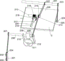
FIG. 1 is a schematic perspective view of a first embodiment of the present invention;
FIG. 2 is a schematic perspective view of a second embodiment of the present invention;
FIG. 3 is a third perspective view of the present invention;
FIG. 4 is a schematic perspective view of a first embodiment of the transfer assembly of the present invention;
FIG. 5 is a schematic perspective view of a second embodiment of the transfer assembly of the present invention;
FIG. 6 is a partial perspective view of the transfer assembly of the present invention;
FIG. 7 is a perspective view of the slider unit of the present invention;
fig. 8 is a perspective view of a first conveyor belt according to the present invention;
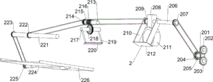
FIG. 9 is a schematic perspective view of a first deboning assembly according to the present invention;
FIG. 10 is a schematic perspective view of a second deboning assembly according to the present invention;
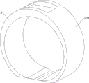
FIG. 11 is a schematic perspective view of a retaining ring according to the present invention;
FIG. 12 is a perspective view of the peeling assembly of the present invention.
Reference numerals: 1_ conveyor assembly, 2_ deboning assembly, 3_ debarking assembly, 4_ console, 5_ first collection bin, 6_ second collection bin, 7_ third collection bin, 101_ cradle table, 102_ main motor, 103_ first shaft, 104_ second shaft, 105_ third shaft, 106_ fourth shaft, 107_ first belt, 108_ second belt, 109_ first drive wheel, 110_ first straight gear, 111_ second drive wheel, 112_ third drive wheel, 113_ transfer drive wheel, 114_ fourth drive wheel, 115_ sixth drive wheel, 116_ electric saw disc, 117_ division plate, 118_ slide unit, 119_ final drive wheel, 11801_ left limit plate, 11802_ right limit plate, 11803_ left slide, 11804_ right slide, 11805_ pallet, 11806_ guide plate, 11807_ fishbone slide, 11808_ slide, 201_ electric slide, 202_ straight gear, 203_ third spur gear, 204_ fourth spur gear, 205_ seventh transmission wheel, 206_ fifth rotation shaft, 207_ eighth transmission wheel, 208_ first mount, 209_ ninth transmission wheel, 210_ adapter plate, 211_ fixed ring, 212_ doctor, 213_ sixth rotation shaft, 214_ tenth transmission wheel, 215_ eleventh transmission wheel, 216_ worm, 217_ seventh rotation shaft, 218_ worm wheel, 219_ adapter rod, 220_ razor, 221_ eighth rotation shaft, 222_ twelfth transmission wheel, 223_ thirteenth transmission wheel, 224_ ninth rotation shaft, 225_ fourteenth transmission wheel, 226_ tray, 301_ second mount 303, 302_ secondary motor, 307_ tenth rotation shaft, 304_ sawtooth rack, 305_ eleventh rotation shaft, 306_ down roller, 307_ up roller, 308_ fifteenth transmission wheel, 309_ fifth spur gear, 310_ sixth spur gear, 311_ swash plate.
Detailed Description
The present invention will be described in detail below with reference to the accompanying drawings.
Example 1
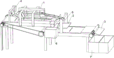
An integrated device for dissecting, boning and peeling a squid head, as shown in figures 1-12, comprises a conveying component 1, a boning component 2, a peeling component 3, a control console 4, a first collecting box 5, a second collecting box 6 and a third collecting box 7; the deboning component 2 is connected with the conveying component 1; the peeling component 3 is connected with the conveying component 1; the control console 4 is connected with the conveying assembly 1; the first collecting box 5 is connected with the conveying assembly 1; the second collecting box 6 is connected with the conveying assembly 1; the third collecting bin 7 is connected to the transferring assembly 1.
When the device is used, the device is placed and kept stable, a power supply is connected externally, and a control console 4 is used for regulating the device, firstly, the killed squid is manually placed in a conveying assembly 1 in a posture that the body of the squid exceeds the front end and faces backwards, the head of the squid is disassembled and planed by the conveying assembly 1 and then conveyed to processing units of a bone-picking assembly 2, the trunk and the head of the squid are separated by the bone-picking assembly 2, the bones of the squid are picked by the bone-picking assembly 2, the trunk and the bones of the separated squid sequentially fall into a first collecting box 5 and a second collecting box 6 to be recovered, then the head of the squid is conveyed to a peeling assembly 3 by the conveying assembly 1, the skin of the head of the squid is cut by the peeling assembly 3, and the processed skin and the cut skin of the squid are respectively fallen into two boxes in a third collecting box 7 to be recovered; the invention realizes that the head of the squid is sequentially subjected to head stripping treatment, the trunk of the squid is separated from the head of the squid, the bones of the squid are removed, and the skin of the head of the squid is cut off, and can realize multi-unit simultaneous treatment of a plurality of squids, and the operation is simple, safe and reliable.
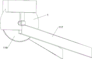
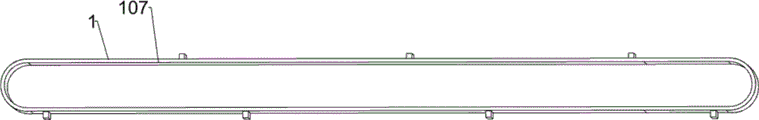
The conveying assembly 1 comprises a support table 101, a main motor 102, a first rotating shaft 103, a second rotating shaft 104, a third rotating shaft 105, a fourth rotating shaft 106, a first conveying belt 107, a second conveying belt 108, a first driving wheel 109, a first straight gear 110, a second driving wheel 111, a third driving wheel 112, a transfer driving wheel 113, a fourth driving wheel 114, a sixth driving wheel 115, an electric saw disc 116, a distributing plate 117, a sliding plate unit 118 and a final conveying wheel 119; the bracket platform 101 is connected with the deboning component 2; one side of the support table 101 is fixedly connected with a main motor 102; the first rotating shaft 103 is rotatably connected with the support table 101; the first rotating shaft 103 is fixedly connected with the main motor 102; on one side of the first rotating shaft 103, a second rotating shaft 104 is rotatably connected with the support table 101; a third rotating shaft 105 is rotatably connected with the support table 101 below one side of the second rotating shaft 104; a fourth rotating shaft 106 is rotatably connected with the support table 101 below the other side of the second rotating shaft 104; the first rotating shaft 103 is in transmission connection with one end of a first conveyor belt 107; the second rotating shaft 104 is in transmission connection with the other end of the first conveyor belt 107; the third rotating shaft 105 is in transmission connection with one end of the second conveyor belt 108; the fourth rotating shaft 106 is in transmission connection with the other end of the second conveyor belt 108; a first driving wheel 109 is fixedly connected with the first rotating shaft 103 at one side of the first conveying belt 107; on the other side of the first conveyor belt 107, a first straight gear 110 and a second driving wheel 111 are respectively fixedly connected with the first rotating shaft 103; when the first straight gear 110 is connected with the deboning assembly 2, the deboning assembly 2 works; when the first straight gear 110 is not connected with the deboning component 2, the deboning component 2 is not moved; above the first spur gear 110, the console 4 is connected with the rack table 101; the third driving wheel 112 is fixedly connected with one side of the second rotating shaft 104; the second transmission wheel 111 is in transmission connection with a third transmission wheel 112 through a belt; on both sides of the second conveyor belt 108, a transfer driving wheel 113 and a fourth driving wheel 114 are respectively fixedly connected with the third rotating shaft 105; the first driving wheel 109 is in transmission connection with a transfer driving wheel 113 through a belt; on both sides of the second conveyor belt 108, a sixth driving wheel 115 and a final conveyor wheel 119 are respectively fixedly connected with the fourth rotating shaft 106; the fourth driving wheel 114 is in driving connection with a sixth driving wheel 115 through a belt; an electric saw tooth disc 116 is fixedly connected with the support table 101 above one side of the first conveyor belt 107 close to the first rotating shaft 103; two sides of the electric saw tooth disc 116 are respectively contacted with one end surface of a group of distributing plates 117; the slide plate unit 118 is connected with the gantry 101; the other ends of the two groups of shifting plates 117 are respectively connected with a sliding plate unit 118; on both sides of one end of the sliding plate unit 118 away from the distributor plate 117, the first collecting box 5 and the second collecting box 6 are respectively in contact with the rack table 101; one end of the bracket platform 101 far away from the main motor 102 is connected with the peeling assembly 3; the final conveying wheel 119 is connected with the peeling assembly 3; below the peeling assembly 3, the third collecting bin 7 is in contact with the stand 101.
Firstly, a main motor 102 drives a first rotating shaft 103 to rotate, the first rotating shaft 103 sequentially drives a first driving wheel 109, a first straight gear 110 and a second driving wheel 111 to rotate, the second driving wheel 111 drives a third driving wheel 112 to rotate through a belt, the first rotating shaft 103 and the second rotating shaft 104 respectively drive a first conveyor belt 107 to rotate, meanwhile, the first driving wheel 109 drives a third rotating shaft 105 to rotate through a belt transmission transfer driving wheel 113, the third rotating shaft 105 drives a fourth driving wheel 114 to rotate, the fourth driving wheel 114 drives a fourth rotating shaft 106 to rotate through a belt transmission sixth driving wheel 115, the third rotating shaft 105 and the fourth rotating shaft 106 respectively drive a second conveyor belt 108 to rotate, meanwhile, the fourth rotating shaft 106 drives a tail conveying wheel 119 to rotate, the tail conveying wheel 119 rotates to drive a peeling component 3 to work, and simultaneously, a motor on an electric saw disc 116 drives a saw disc to work, then, the killed squid is manually placed on a first conveyor belt 107 in a posture that the body of the squid exceeds the front end and faces backwards, the first conveyor belt 107 drives the squid to sequentially pass through an electric saw tooth disc 116 and a bone-picking assembly 2, when the head of the squid passes through the electric saw tooth disc 116, the electric saw tooth disc 116 cuts one side of the upward head of the squid into two halves, the two halves of the head of the cut squid are respectively unfolded towards two sides along a distributing plate 117, then the first conveyor belt 107 drives the squid to enter the lower part of a sliding plate unit 118, when the squid passes through the bone-picking assembly 2, the bone-picking assembly 2 sequentially separates the trunk and the head of the squid and removes the bones of the squid, the trunk and the bones of the separated squid sequentially fall to a second collecting box 6 and a first collecting box 5 along the sliding plate unit 118 to be recovered, and then one end of the first conveyor belt 107, which is far away from a main motor 102, the heads of the rest squids are suspended downwards from the first conveyor belt 107 in a posture that the inner meat faces upwards and the outer skin faces downwards, then the inner meat of the heads of the squids is contacted with the boning component 2, under the transmission of the first conveyor belt 107, the heads of the squids finally fall on the boning component 2 in a posture that the inner meat faces downwards and the outer skin faces upwards, then the heads of the squids slide down from the boning component 2 to the second conveyor belt 108 in a posture that the inner meat faces downwards and the outer skin faces upwards, the heads of the squids are conveyed to the peeling component 3 by the second conveyor belt 108, the outer skin of the heads of the squids is cut by the peeling component 3, and the processed squids and the cut outer skin respectively fall into two boxes in the third collecting box 7 to be recovered; in addition, when the deboning component 2 needs to work, the deboning component 2 starts to work when the first straight gear 110 is connected with the deboning component 2; the assembly completes the cutting of the upward side of the head of the squid into two halves, and completes the conveying of the squid to the boning assembly 2 and the skinning assembly 3 for processing.
The sliding plate unit 118 includes a left limit plate 11801, a right limit plate 11802, a left sliding plate 11803, a right sliding plate 11804, a supporting plate 11805, a guide plate 11806, a fishbone sliding plate 11807 and a trunk sliding plate 11808; above the first conveyor belt 107, a left limit plate 11801 and a right limit plate 11802 are fixedly connected with two sides of the support platform 101 respectively; one ends of the left limit plate 11801 and the right limit plate 11802 close to the electric saw toothed disc 116 are fixedly connected with a group of distributing plates 117 respectively; one side of the left limit plate 11801, which is close to the right limit plate 11802, is fixedly connected with the left sliding plate 11803; one side of the right limit plate 11802 close to the left limit plate 11801 is fixedly connected with the right sliding plate 11804; two sides of the supporting plate 11805 are fixedly connected with the left sliding plate 11803 and the right sliding plate 11804 respectively below the distributing plate 117; the guide plate 11806 is fixedly connected with the top ends of the left sliding plate 11803 and the supporting plate 11805 in sequence; the side surface of the guide plate 11806 close to the dial plate 117 is designed as an inclined surface, and the right sliding plate 11804 faces the inclined surface of the guide plate 11806; the left sliding plate 11803 and the right sliding plate 11804 are designed to be inclined, wherein the height of one side close to the supporting plate 11805 is higher, and the height of one side far away from the supporting plate 11805 is lower; the left sliding plate 11803 and the right sliding plate 11804 are designed to be inclined, wherein one side of the left sliding plate 11803 close to the distribution plate 117 is high, and the other side of the left sliding plate 11804 far from the distribution plate 117 is low; one side of the left sliding plate 11803, which is far away from the shifting plate 117, is fixedly connected with the fishbone sliding plate 11807; one side of the right sliding plate 11804 far away from the shifting plate 117 is fixedly connected with a trunk sliding plate 11808; fishbone slide 11807 and torso slide 11808 are angled with a high side near blade 11805 and a low side away from blade 11805.
The electric saw fluted disc 116 cuts one side of the squid with the upward head part into two parts, the two sides of the cut head part of the squid are respectively unfolded towards two sides along the distributing plate 117 and respectively enter the lower parts of the left limiting plate 11801 and the right limiting plate 11802, when the squid passes through the bone-removing assembly 2, the bone-removing assembly 2 sequentially separates the trunk and the head part of the squid and removes the bones of the squid, the trunk of the separated squid slides into the right sliding plate 11804 along the guide plate 11806 and the supporting plate 11805, the trunk of the separated squid sequentially slides to the first collecting box 5 along the right sliding plate 11804 and the trunk sliding plate 11808 for recovery, meanwhile, the bone head of the squid is removed into the left sliding plate 11803, and the removed bone sequentially slides to the second collecting box 396 along the left sliding plate 11803 and the fishbone sliding plate 11807 for recovery.
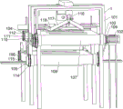
The deboning assembly 2 comprises an electric sliding block 201, a second straight gear 202, a third straight gear 203, a fourth straight gear 204, a seventh transmission wheel 205, a fifth rotating shaft 206, an eighth transmission wheel 207, a first fixing frame 208, a ninth transmission wheel 209, an adapter plate 210, a fixing ring 211, a scraper 212, a sixth rotating shaft 213, a tenth transmission wheel 214, an eleventh transmission wheel 215, a worm 216, a seventh rotating shaft 217, a worm wheel 218, an adapter rod 219, a shaver 220, an eighth rotating shaft 221, a twelfth transmission wheel 222, a thirteenth transmission wheel 223, a ninth rotating shaft 224, a fourteenth transmission wheel 225 and a tray 226; under the control console 4, the electric slide block 201 is connected with the support table 101 in a sliding manner; the second straight gear 202 and the third straight gear 203 are respectively in rotary connection with the electric sliding block 201 through a rotating shaft; on one side of the electric slider 201, the fourth spur gear 204 and the seventh transmission wheel 205 are fixedly connected with the same rotating shaft, and the fourth spur gear 204 and the seventh transmission wheel 205 are respectively in rotating connection with the support platform 101 through the rotating shaft; when both sides of the second spur gear 202 are engaged with the first spur gear 110 and the fourth spur gear 204, respectively, the second spur gear 202 and the fourth spur gear 204 rotate; when both sides of the second spur gear 202 are not engaged with the first spur gear 110 and the fourth spur gear 204, the second spur gear 202 and the fourth spur gear 204 do not rotate; when both sides of the third spur gear 203 are engaged with the first spur gear 110 and the fourth spur gear 204, respectively, the third spur gear 203 and the fourth spur gear 204 rotate; when both sides of the third spur gear 203 are not engaged with the first spur gear 110 and the fourth spur gear 204, the third spur gear 203 and the fourth spur gear 204 do not rotate; a fifth rotating shaft 206 is rotatably connected with the support platform 101 above one side of the fourth spur gear 204; the eighth driving wheel 207, the first fixing frame 208 and the ninth driving wheel 209 are fixedly connected with the fifth rotating shaft 206 in sequence; the seventh driving wheel 205 is in driving connection with the eighth driving wheel 207 through a belt; a group of adapter plates 210 are respectively fixedly connected with the fifth rotating shaft 206 at two sides of the first fixing frame 208 and the ninth driving wheel 209; the two groups of adapter plates 210 are respectively fixedly connected with the scraper 212; the fixing ring 211 is fixedly connected with the bottom end of the first fixing frame 208; on one side of the fifth rotating shaft 206, a sixth rotating shaft 213 is rotatably connected with the support table 101; the tenth driving wheel 214, the eleventh driving wheel 215 and the worm 216 are fixedly connected with the sixth rotating shaft 213 in sequence; the ninth driving wheel 209 is in driving connection with the eleventh driving wheel 215 through a belt; below the worm 216, the seventh rotating shaft 217 is in rotational connection with the support table 101; the worm gear 218 is fixedly connected with the seventh rotating shaft 217; worm 216 meshes with worm gear 218; a group of adapter rods 219 are respectively arranged on two sides of the worm gear 218 and fixedly connected with the seventh rotating shaft 217; the two groups of the switching rods 219 are respectively fixedly connected with the shaver 220; on one side of the seventh rotating shaft 217, an eighth rotating shaft 221 is rotatably connected with the support table 101; the twelfth driving wheel 222 and the thirteenth driving wheel 223 are respectively fixedly connected with the eighth rotating shaft 221; the tenth driving wheel 214 is in driving connection with a twelfth driving wheel 222 through a belt; a ninth rotating shaft 224 is rotatably connected to the support table 101 below one side of the eighth rotating shaft 221; the fourteenth driving wheel 225 is fixedly connected with the ninth rotating shaft 224; the thirteenth driving wheel 223 is in driving connection with the fourteenth driving wheel 225 through a belt; above the second conveyor belt 108, the tray 226 is fixedly connected with the ninth rotating shaft 224; the tray 226 is of a damperless design on the side adjacent to the peeling assembly 3.
When the squid with the head cut passes through the fixing ring 211, one side of the body of the squid slides to the right sliding plate 11804 along the middle of the fixing ring 211, the scraper 212 and the guide plate 11806 in sequence, meanwhile, the head of the squid passes below the fixing ring 211, then the electric slide block 201 drives the second spur gear 202 and the third spur gear 203 to move upwards through the rotating shaft, so that the first spur gear 110 is meshed with the third spur gear 203 to drive the squid to rotate, the third spur gear 203 is meshed with the fourth spur gear 204 to drive the seventh transmission wheel 205 to rotate through the rotating shaft, the seventh transmission wheel 205 drives the eighth transmission wheel 207 through the belt to drive the first fixing frame 208, the ninth transmission wheel 209, the adapter plate 210 and the scraper 212 connected with the first transmission wheel 207 through the fifth rotating shaft 206 to rotate around the shaft center of the fifth rotating shaft 206, so that the scraper 212 is positioned right below the fixing ring 211, when the first transmission belt 107 transmits the squid, the joint of the head and the body of the squid can be cut, meanwhile, the body of the squid can continuously slide to the right sliding plate 11804 along the middle of the fixing ring 211 and the guide plate 11806 and finally slide to the first collecting box 5 for recovery, then the electric slide block 201 drives the second spur gear 202 and the third spur gear 203 to move downwards through the rotating shaft, so that the first spur gear 110 is meshed with the second spur gear 202 to drive the squid to rotate, the second spur gear 202 is meshed with the fourth spur gear 204 to drive the seventh transmission wheel 205 to rotate reversely through the rotating shaft, so that the scraper 212 is reset, then the head of the squid with the stripped body is conveyed to the lower part of the shaver 220 through the first transmission belt 107 below the fixing ring 211, meanwhile, the next squid to be treated is conveyed to the lower part of the scraper 212 through the first transmission belt 107, then the electric slide block 201 drives the second spur gear 202 and the third spur gear 203 to move upwards through the rotating shaft, so that the first spur gear 110 is meshed with the third spur gear 203 to drive the squid to rotate, the third spur gear 203 is meshed with the fourth spur gear 204 to drive the seventh transmission wheel 205, the ninth transmission wheel 209 drives the eleventh transmission wheel 215 through a belt to drive the tenth transmission wheel 214 and the worm 216 to rotate through the sixth rotating shaft 213, the worm 216 is meshed with the worm wheel 218 to drive the adapter rod 219 and the shaver 220 connected with the adapter rod to rotate around the axis of the seventh rotating shaft 217 through the seventh rotating shaft 217, so that the shaver 220 slides along the inner meat surface of the head of the squid and rejects bones in the middle of the head of the squid into the left sliding plate 11803, the rejected bones slide down to the second collection box 6 along the left sliding plate 11803 and the fishbone sliding plate 11807 to be recovered, meanwhile, the scraper 212 peels off the trunk and the head of the next squid, then the electric sliding block 201 drives the second spur gear 202 and the third spur gear 203 to move downwards through the rotating shaft, so that the first spur gear 110 is meshed with the second spur gear 202 to drive the rotation thereof, the second spur gear 202 is meshed with the fourth spur gear 204 to drive the seventh transmission wheel 205 to rotate reversely through the rotating shaft, the shaver 220 and the scraper 212 are reset, the head of the rest squid is suspended downwards from the first conveyor belt 107 in a posture that the inner meat faces upwards and the outer skin faces downwards, then the inner meat of the head of the squid is contacted with the tray 226, under the transmission of the first conveyor belt 107, finally the head of the squid drops on the tray 226 in a posture that the inner meat faces downwards and the outer skin faces upwards, then the electric slider 201 drives the second spur gear 202 and the third spur gear 203 to move upwards through the rotating shaft, so that the first spur gear 110 is meshed with the third spur gear 203 to drive the third spur gear 203 to rotate, the third spur gear 203 is meshed with the fourth spur gear 204 to drive the seventh transmission wheel 205 to rotate through the rotating shaft, the tenth transmission wheel 214 drives the twelfth transmission wheel 222 to drive the thirteenth transmission wheel 223 to rotate through the eighth rotating shaft 221 through the belt, the thirteenth transmission wheel 223 drives the tray 226 to rotate around the axis of the ninth rotating shaft 224 through the fourteenth transmission wheel 225, the sleeve-fish head slides from the deboning component 2 to the second conveyor belt 108 in a state that the inner meat faces downwards and the outer skin faces upwards; this accomplished the trunk and the head of squid and peeled off the processing and reject the bone in the middle of the squid head and handle to accomplished the head that will remain the squid and carried out turn-over processing work.
Wherein, the peeling assembly 3 comprises a second fixed frame 301, an auxiliary motor 302, a tenth rotating shaft 303, a sawtooth rack 304, an eleventh rotating shaft 305, a lower roller 306, an upper roller 307, a fifteenth driving wheel 308, a fifth spur gear 309, a sixth spur gear 310 and an inclined plate 311; on the side of the second conveyor belt 108 far away from the first conveyor belt 107, the second fixing frame 301 is fixedly connected with the support table 101; the auxiliary motor 302 is fixedly connected with one end of the second fixing frame 301; the tenth rotating shaft 303 and the eleventh rotating shaft 305 are respectively and rotatably connected with two sides of one end of the second fixing frame 301, which is far away from the first conveyor belt 107; the auxiliary motor 302 is fixedly connected with the tenth rotating shaft 303; a rotating part at one end of the sawtooth strip 304 is fixedly connected with the tenth rotating shaft 303 between the second conveyor belt 108 and the second fixed frame 301; a rotating part at the other end of the sawtooth rack 304 is fixedly connected with the eleventh rotating shaft 305; on one side of the sawtooth rack 304, a lower roller 306 is rotatably connected with the support table 101; above the lower roller 306, the upper roller 307 is rotatably connected with the support table 101; a fifteenth driving wheel 308 and a fifth spur gear 309 are respectively and fixedly connected with one side of the lower roller 306; the final conveying wheel 119 is in transmission connection with a fifteenth transmission wheel 308 through a belt; the sixth spur gear 310 is fixedly connected with one side of the upper roller 307; the fifth spur gear 309 is meshed with the sixth spur gear 310; on the side between the upper roller 307 and the lower roller 306, a swash plate 311 is fixed to the carriage 101.
Firstly, the auxiliary motor 302 drives the sawtooth rack 304 to work through a tenth rotating shaft 303, meanwhile, the ending transmission wheel 119 drives a fifteenth transmission wheel 308 through a belt to drive a lower roller 306 to rotate through the rotating shaft, the lower roller 306 drives a fifth spur gear 309 to rotate, the fifth spur gear 309 is meshed with a sixth spur gear 310 to drive an upper roller 307 to rotate, the squid which is turned over by the bone picking component 2 slides from the bone picking component 2 to the second transmission belt 108 in a state that the inner meat faces downwards and the outer skin faces upwards, the second transmission belt 108 transmits the squid to pass through the lower part of the second fixed frame 301, then when one side of the squid is contacted with the sawtooth rack 304, the sawtooth rack 304 cuts and separates the outer skin of the head part of the squid and the inner meat of the head part of the squid, the separated outer skin respectively enters between the lower roller 306 and the upper roller 307 along the upper part of the sawtooth rack 304, the separated outer skin is rolled on the inclined plate 311 along with the rotation of the lower roller 306 and the upper roller 307, after the outer skin and the inner meat are completely cut off, the processed head falls into the box body on one side, close to the second conveyor belt 108, of the third collecting box 7 along the second conveyor belt 108, and meanwhile, the peeled outer skin slides into the box body on one side, far away from the second conveyor belt 108, of the third collecting box 7 along the inclined plate 311; this subassembly has accomplished to cut the crust of squid head and interior meat from handling to accomplished to throw the crust of squid head and interior meat respectively to retrieve in the box of 7 both sides of third collecting box.
The distributing plate 117 is designed to be higher on the side close to the electric saw disc 116 and lower on the side far from the electric saw disc 116.
The head parts of the squid which are cut at the two sides can be respectively unfolded towards the two sides along the distributing plate 117 and enter the lower part of the sliding plate unit 118 along the distributing plate 117.
Wherein seven sets of raised strips are provided around the outer surface of each of the first conveyor belt 107 and the second conveyor belt 108.
The squid can be pushed by the convex strips on the first conveyor belt 107 and the second conveyor belt 108 to carry out conveying work.
The inner bottom end of the fixing ring 211 is designed to be lower at one side close to the electric saw disc 116 and higher at one side far away from the electric saw disc 116.
The body of the squid may be slid along the inner bottom end of the fixing ring 211 from the surface of the first conveyor belt 107 to above the sliding plate unit 118.
While the present invention has been described with reference to exemplary embodiments, it is to be understood that the invention is not limited to the disclosed exemplary embodiments. The scope of the following claims is to be accorded the broadest interpretation so as to encompass all such modifications and equivalent structures and functions.
Claims (8)
1. A squid head dissects and picks bone and peels integrative device, including the first collecting box, the second collecting box and third collecting box, characterized by, including conveying assembly, picking bone assembly, peeling assembly and control cabinet; the deboning component is connected with the conveying component; the peeling assembly is connected with the conveying assembly; the console is connected with the conveying assembly; the first collecting box is connected with the conveying assembly; the second collecting box is connected with the conveying assembly; the third collecting box is connected with the conveying assembly.
2. The integrated device for dissecting, boning and skinning the head of a squid as claimed in claim 1, wherein the conveying assembly comprises a support stand, a main motor, a first rotating shaft, a second rotating shaft, a third rotating shaft, a fourth rotating shaft, a first conveyor belt, a second conveyor belt, a first driving wheel, a first straight gear, a second driving wheel, a third driving wheel, a transfer driving wheel, a fourth driving wheel, a sixth driving wheel, an electric saw tooth disc, a dividing and shifting plate, a sliding plate unit and a tailing conveying wheel; the bracket platform is connected with the deboning component; one side of the support platform is fixedly connected with a main motor; the first rotating shaft is rotatably connected with the support table; the first rotating shaft is fixedly connected with the main motor; the second rotating shaft is rotatably connected with the support platform on one side of the first rotating shaft; the third rotating shaft is rotatably connected with the support platform below one side of the second rotating shaft; a fourth rotating shaft is rotatably connected with the support platform below the other side of the second rotating shaft; the first rotating shaft is in transmission connection with one end of the first conveying belt; the second rotating shaft is in transmission connection with the other end of the first conveyor belt; the third rotating shaft is in transmission connection with one end of the second conveying belt; the fourth rotating shaft is in transmission connection with the other end of the second conveying belt; a first driving wheel is fixedly connected with a first rotating shaft at one side of the first conveyor belt; on the other side of the first conveyor belt, a first straight gear and a second driving wheel are fixedly connected with a first rotating shaft respectively; when the first straight gear is connected with the deboning component, the deboning component works; when the first straight gear is not connected with the deboning component, the deboning component is not moved; the control console is connected with the support platform above the first straight gear; the third driving wheel is fixedly connected with one side of the second rotating shaft; the second transmission wheel is in transmission connection with the third transmission wheel through a belt; on two sides of the second conveyor belt, a transfer driving wheel and a fourth driving wheel are fixedly connected with a third rotating shaft respectively; the first driving wheel is in transmission connection with the transfer driving wheel through a belt; a sixth driving wheel and a final conveying wheel are fixedly connected with the fourth rotating shaft respectively on two sides of the second conveying belt; the fourth transmission wheel is in transmission connection with the sixth transmission wheel through a belt; the electric saw tooth disc is fixedly connected with the support table above one side of the first conveyor belt, which is close to the first rotating shaft; two sides of the electric saw tooth disc are respectively contacted with one end surface of the group of distributing plates; the sliding plate unit is connected with the support platform; the other ends of the two groups of shifting plates are respectively connected with the sliding plate unit; the first collecting box and the second collecting box are respectively contacted with the support platform on two sides of one end of the sliding plate unit, which is far away from the distributing plate; one end of the support platform, which is far away from the main motor, is connected with the peeling assembly; the ending transmission wheel is connected with the peeling component; below the peeling assembly, a third collecting bin is in contact with the support stand.
3. The integrated device for dissecting, boning and skinning the head of a squid as claimed in claim 2, wherein the sliding plate unit comprises a left limiting plate, a right limiting plate, a left sliding plate, a right sliding plate, a supporting plate, a guiding plate, a fishbone sliding plate and a trunk sliding plate; above the first conveyor belt, a left limit plate and a right limit plate are fixedly connected with two sides of the support platform respectively; one ends of the left limiting plate and the right limiting plate, which are close to the electric saw tooth disc, are fixedly connected with a group of distributing plates respectively; one side of the left limit plate, which is close to the right limit plate, is fixedly connected with the left sliding plate; one side of the right limit plate, which is close to the left limit plate, is fixedly connected with the right sliding plate; two sides of the supporting plate are fixedly connected with the left sliding plate and the right sliding plate respectively below the distributing plate; the guide plate is fixedly connected with the top ends of the left sliding plate and the supporting plate in sequence; the side surface of the guide plate close to the dial plate is designed to be an inclined surface, and the guide plate faces the inclined surface right sliding plate; the left sliding plate and the right sliding plate are respectively designed to be inclined, wherein one side of the left sliding plate close to the supporting plate is high, and one side of the right sliding plate far away from the supporting plate is low; the left sliding plate and the right sliding plate are respectively designed to be inclined, wherein one side of the left sliding plate close to the distributing plate is high, and one side of the right sliding plate far away from the distributing plate is low; one side of the left sliding plate, which is far away from the shifting plate, is fixedly connected with the fishbone sliding plate; one side of the right sliding plate, which is far away from the shifting plate, is fixedly connected with the trunk sliding plate; the fishbone slide plate and the trunk slide plate are respectively designed to be inclined with one side close to the supporting plate higher and one side far away from the supporting plate lower.
4. The integrated device for dissecting, boning and skinning the head of the squid as claimed in claim 3, wherein the boning component comprises an electric slider, a second spur gear, a third spur gear, a fourth spur gear, a seventh transmission wheel, a fifth rotating shaft, an eighth transmission wheel, a first fixing frame, a ninth transmission wheel, an adapter plate, a fixing ring, a scraper, a sixth rotating shaft, a tenth transmission wheel, an eleventh transmission wheel, a worm, a seventh rotating shaft, a worm wheel, an adapter rod, a shaver, an eighth rotating shaft, a twelfth transmission wheel, a thirteenth transmission wheel, a ninth rotating shaft, a fourteenth transmission wheel and a tray; the electric sliding block is connected with the support table in a sliding manner below the control table; the second straight gear and the third straight gear are respectively in rotary connection with the electric slide block through a rotating shaft; on one side of the electric sliding block, a fourth straight gear and a seventh transmission wheel are fixedly connected with the same rotating shaft, and the fourth straight gear and the seventh transmission wheel are respectively in rotating connection with the support platform through the rotating shaft; when two sides of the second straight gear are respectively meshed with the first straight gear and the fourth straight gear, the second straight gear and the fourth straight gear rotate; when the two sides of the second straight gear are not meshed with the first straight gear and the fourth straight gear, the second straight gear and the fourth straight gear do not rotate; when two sides of the third straight gear are respectively meshed with the first straight gear and the fourth straight gear, the third straight gear and the fourth straight gear rotate; when the two sides of the third straight gear are not meshed with the first straight gear and the fourth straight gear, the third straight gear and the fourth straight gear do not rotate; a fifth rotating shaft is rotatably connected with the support platform above one side of the fourth straight gear; the eighth driving wheel, the first fixing frame and the ninth driving wheel are fixedly connected with the fifth rotating shaft in sequence; the seventh driving wheel is in transmission connection with the eighth driving wheel through a belt; a group of adapter plates are respectively arranged on two sides of the first fixed frame and the ninth driving wheel and fixedly connected with the fifth rotating shaft; the two groups of adapter plates are fixedly connected with the scraper respectively; the fixing ring is fixedly connected with the bottom end of the first fixing frame; on one side of the fifth rotating shaft, the sixth rotating shaft is rotatably connected with the support table; the tenth driving wheel, the eleventh driving wheel and the worm are fixedly connected with the sixth rotating shaft in sequence; the ninth transmission wheel is in transmission connection with the eleventh transmission wheel through a belt; the seventh rotating shaft is rotatably connected with the support platform below the worm; the worm wheel is fixedly connected with the seventh rotating shaft; the worm is meshed with the worm wheel; a group of switching rods are respectively arranged at two sides of the worm wheel and fixedly connected with the seventh rotating shaft; the two groups of the switching rods are respectively and fixedly connected with the shaver; on one side of the seventh rotating shaft, the eighth rotating shaft is rotatably connected with the support platform; the twelfth driving wheel and the thirteenth driving wheel are fixedly connected with the eighth rotating shaft respectively; the tenth driving wheel is in transmission connection with the twelfth driving wheel through a belt; the ninth rotating shaft is rotatably connected with the support platform below one side of the eighth rotating shaft; the fourteenth driving wheel is fixedly connected with the ninth rotating shaft; the thirteenth driving wheel is in transmission connection with the fourteenth driving wheel through a belt; the tray is fixedly connected with the ninth rotating shaft above the second conveyor belt; the tray is designed to be free of baffles on one side close to the peeling assembly.
5. The integral device for dissecting, boning and peeling the head of the squid as claimed in claim 4, wherein the peeling assembly comprises a second fixing frame, an auxiliary motor, a tenth rotating shaft, a sawtooth rack, an eleventh rotating shaft, a lower roller, an upper roller, a fifteenth transmission wheel, a fifth spur gear, a sixth spur gear and an inclined plate; the second fixing frame is fixedly connected with the support platform on one side of the second conveyor belt far away from the first conveyor belt; the auxiliary motor is fixedly connected with one end of the second fixing frame; the tenth rotating shaft and the eleventh rotating shaft are respectively and rotatably connected with two sides of one end, far away from the first conveying belt, of the second fixing frame; the auxiliary motor is fixedly connected with the tenth rotating shaft; a rotating part at one end of the sawtooth strip is fixedly connected with the tenth rotating shaft between the second conveyor belt and the second fixing frame; a rotating part at the other end of the sawtooth strip is fixedly connected with the eleventh rotating shaft; the lower roller is rotatably connected with the support table on one side of the sawtooth strip; the upper roller is rotatably connected with the support table above the lower roller; the fifteenth transmission wheel and the fifth straight gear are fixedly connected with one side of the lower roller respectively; the ending transmission wheel is in transmission connection with a fifteenth transmission wheel through a belt; the sixth straight gear is fixedly connected with one side of the upper roller; the fifth straight gear is meshed with the sixth straight gear; and an inclined plate is fixedly connected with the support platform at one side between the upper roller and the lower roller.
6. The integrated device for boning and skinning in squid head anatomy according to claim 5, wherein the dividing and dialing plate is designed to be high on the side close to the electric saw disc and low on the side far from the electric saw disc.
7. The integrated device for boning and skinning a squid head part as claimed in claim 6, wherein seven groups of convex strips are respectively provided around the outer surfaces of the first conveyor belt and the second conveyor belt.
8. The integrated device for removing bones and peels from the head of a squid as claimed in claim 7, wherein the inner bottom end of the fixing ring is designed to be lower at the side close to the electric saw disc and higher at the side far away from the electric saw disc.
Priority Applications (1)
| Application Number | Priority Date | Filing Date | Title |
|---|---|---|---|
| CN202110079089.5A CN112841277B (en) | 2021-01-21 | 2021-01-21 | Squid head dissects boning and peeling integrated device |
Applications Claiming Priority (1)
| Application Number | Priority Date | Filing Date | Title |
|---|---|---|---|
| CN202110079089.5A CN112841277B (en) | 2021-01-21 | 2021-01-21 | Squid head dissects boning and peeling integrated device |
Publications (2)
| Publication Number | Publication Date |
|---|---|
| CN112841277A true CN112841277A (en) | 2021-05-28 |
| CN112841277B CN112841277B (en) | 2023-06-30 |
Family
ID=76008456
Family Applications (1)
| Application Number | Title | Priority Date | Filing Date |
|---|---|---|---|
| CN202110079089.5A Active CN112841277B (en) | 2021-01-21 | 2021-01-21 | Squid head dissects boning and peeling integrated device |
Country Status (1)
| Country | Link |
|---|---|
| CN (1) | CN112841277B (en) |
Cited By (1)
| Publication number | Priority date | Publication date | Assignee | Title |
|---|---|---|---|---|
| CN114258939A (en) * | 2021-12-01 | 2022-04-01 | 钟露坤 | But preprocessing device of cuttlefish bone of secondary deboning |
Citations (7)
| Publication number | Priority date | Publication date | Assignee | Title |
|---|---|---|---|---|
| DE3216506A1 (en) * | 1981-05-04 | 1982-12-09 | Przedsiębiorstwo Przemysłowo-Handlowe "Centrala Rybna", Poznan | Device for gutting octopuses |
| KR20010035121A (en) * | 2000-12-29 | 2001-05-07 | 이치우 | manufacturing apparatus of a cuttlefish |
| KR20010091511A (en) * | 2000-03-16 | 2001-10-23 | 한수영 | Manufacturing device for cuttle fish |
| KR20030062695A (en) * | 2002-01-18 | 2003-07-28 | 유영환 | Apparatus for extraction a disembowelment and entrails of squid |
| KR20130142694A (en) * | 2012-06-20 | 2013-12-30 | (주)제피드 | Manufacturing apparatus of a cuttlefish |
| CN104304407A (en) * | 2014-10-20 | 2015-01-28 | 烟台新大洋水产食品有限公司 | Initial marine processing method for ship-fished squid and special equipment thereof |
| CN208624467U (en) * | 2018-03-09 | 2019-03-22 | 山东新希望六和集团有限公司 | A kind of novel duck wing cutting machine |
-
2021
- 2021-01-21 CN CN202110079089.5A patent/CN112841277B/en active Active
Patent Citations (7)
| Publication number | Priority date | Publication date | Assignee | Title |
|---|---|---|---|---|
| DE3216506A1 (en) * | 1981-05-04 | 1982-12-09 | Przedsiębiorstwo Przemysłowo-Handlowe "Centrala Rybna", Poznan | Device for gutting octopuses |
| KR20010091511A (en) * | 2000-03-16 | 2001-10-23 | 한수영 | Manufacturing device for cuttle fish |
| KR20010035121A (en) * | 2000-12-29 | 2001-05-07 | 이치우 | manufacturing apparatus of a cuttlefish |
| KR20030062695A (en) * | 2002-01-18 | 2003-07-28 | 유영환 | Apparatus for extraction a disembowelment and entrails of squid |
| KR20130142694A (en) * | 2012-06-20 | 2013-12-30 | (주)제피드 | Manufacturing apparatus of a cuttlefish |
| CN104304407A (en) * | 2014-10-20 | 2015-01-28 | 烟台新大洋水产食品有限公司 | Initial marine processing method for ship-fished squid and special equipment thereof |
| CN208624467U (en) * | 2018-03-09 | 2019-03-22 | 山东新希望六和集团有限公司 | A kind of novel duck wing cutting machine |
Cited By (1)
| Publication number | Priority date | Publication date | Assignee | Title |
|---|---|---|---|---|
| CN114258939A (en) * | 2021-12-01 | 2022-04-01 | 钟露坤 | But preprocessing device of cuttlefish bone of secondary deboning |
Also Published As
| Publication number | Publication date |
|---|---|
| CN112841277B (en) | 2023-06-30 |
Similar Documents
| Publication | Publication Date | Title |
|---|---|---|
| CN110679967B (en) | Full-automatic intelligent pineapple peeling and hole removing all-in-one machine | |
| CN1031013A (en) | Reclaim the technology and the device of meat from animal carcase section | |
| DK155414B (en) | APPARATUS FOR REMOVING THE MEAT PIECES FROM THE SUCCESSFUL REMOVAL BREAK | |
| CN106818044B (en) | Green soy bean gathers in threshing skinning machine | |
| EP2704581B1 (en) | Poultry neck meat harvester and method for mechanized harvesting of poultry neck meat | |
| CN107647456B (en) | Agricultural green Chinese onion processing apparatus | |
| CN108064545B (en) | full-automatic kenaf reaps all-in-one | |
| CN112244313A (en) | Pumpkin processing device capable of peeling, removing pulp and slicing | |
| CN112841277A (en) | Integrated device for dissecting, boning and peeling sleeve-fish head | |
| CN204837774U (en) | Device is slaughtered to full -automatic rice field eel | |
| CN101703091B (en) | Full-automatic dissecting bone extractor for eel | |
| CN104996537B (en) | Full-automatic ricefield eel slaughtering device | |
| CN108673630A (en) | A kind of taro automatic strip-cutting machine | |
| CN113068848A (en) | Coconut peeling and meat taking integrated device | |
| CN107581627A (en) | Bamboo shoots peeling machine | |
| US20130280998A1 (en) | Combination automated & hand deboning apparatus & method with single unit processing | |
| US5664490A (en) | Melon peeler apparatus | |
| CN215189075U (en) | Full-automatic hatching of live eel is killed and is removed miscellaneous device | |
| CN112741146B (en) | Broken-end combined separation hairtail treatment device | |
| CN213674287U (en) | Dicing device for meat product processing | |
| CN112976121A (en) | Incomplete cutting device for removing outer leaf base part of dried ballonflower | |
| CN113016859A (en) | Internal organ and scale scraping device for edible sea snakes | |
| JP2000106774A (en) | Harvesting device | |
| CN112189865A (en) | Kiwi fruit treatment device capable of removing epidermis | |
| CN208403172U (en) | Bamboo shoots peeling machine |
Legal Events
| Date | Code | Title | Description |
|---|---|---|---|
| PB01 | Publication | ||
| PB01 | Publication | ||
| SE01 | Entry into force of request for substantive examination | ||
| SE01 | Entry into force of request for substantive examination | ||
| TA01 | Transfer of patent application right | ||
| TA01 | Transfer of patent application right |
Effective date of registration: 20230607 Address after: 210000 288 Qinhuai Road, Yung Yang Street, Lishui District, Nanjing, Jiangsu Applicant after: Nanjing 66 venture Technology Co.,Ltd. Address before: 434000 room 506, building D, commercial pedestrian street, Stadium Road, Jingzhou District, Jingzhou City, Hubei Province Applicant before: Jia Shuangshuang |
|
| GR01 | Patent grant | ||
| GR01 | Patent grant |