Disclosure of Invention
The chip positioning device for the smart phone enables the output end to drive the chip to move upwards until the chip can block light rays emitted by the light emitter, so that the chip always keeps a certain height, the descending distance of the rod body is reduced, the time is saved, and the working efficiency is improved.
In order to achieve the purpose, the invention adopts the technical scheme that: a chip positioning device for a smart phone comprises a workbench, a support, a longitudinal driving mechanism, a containing box, a transverse driving mechanism and a rod body mechanism, wherein the support is arranged on the upper surface of the workbench, the containing box is slidably mounted on the support, a transverse plate is arranged below a top plate of the support, the longitudinal driving mechanism is positioned between the top plate and the transverse plate of the support, the longitudinal driving mechanism penetrates through the containing box and is fixedly connected with the containing box, the transverse driving mechanism is mounted in an inner cavity of the containing box and is fixedly connected with the rod body mechanism, a chain plate conveying belt is mounted below the transverse plate of the support, and a plurality of placing grooves for embedding cards are formed in the chain plate conveying belt;
the automatic feeding device comprises a rod body mechanism, a rotary table, a plurality of placing barrels, a workbench, a pressing mechanism, a sucking mechanism, a rotating motor and a feeding mechanism, wherein the rod body mechanism is provided with a shell, the pressing mechanism is fixed in an inner cavity of the shell, the sucking mechanism is installed in the inner cavity of the rod body mechanism, the rotary table is rotatably arranged below the rod body mechanism, the rotary table is provided with the plurality of placing barrels, the inner cavity of the workbench is provided with the rotating motor, and an output shaft of the rotating motor is connected with the rotary table and used for driving the rotary table to rotate;
the rod body mechanism further comprises a first rod body, a bearing and a second rod body, the first rod body and the second rod body are connected through the bearing, one end of the first rod body is fixedly connected with the transverse driving mechanism, the other end of the first rod body is fixedly connected with an outer ring of the bearing, one end, opposite to the first rod body, of the bearing is connected with the second rod body, the second rod body is fixedly connected with an inner ring of the bearing, and the shell is arranged at the upper end of the second rod body;
an adjusting motor is fixedly arranged in the inner cavity of the first rod body, a cylinder is fixedly arranged on an output shaft of the adjusting motor, and one end of the cylinder, which is back to the adjusting motor, is fixedly connected with an inner ring of the bearing;
the suction mechanism further comprises a vacuum suction pump, a suction pipe and a rubber sucker, the vacuum suction pump is positioned in the cylinder, one end of the suction pipe is connected with the vacuum suction pump, the other end of the suction pipe extends to the inner cavity of the second rod body and penetrates through the inner cavity wall of the second rod body to extend to the lower part of the inner cavity wall, and the rubber sucker is fixed on the outer wall of the lower end of the suction pipe;
the mechanism of pushing down further includes motor, push down lead screw, movable rod, push down nut, fixed plate and push down the pole, the motor sets up in the casing upper surface down, the fixed plate is located the casing inner chamber, it is equipped with the push down lead screw to rotate between fixed plate and the casing, the upper end of push down the lead screw run through the casing and with the output fixed connection of push down the motor, push down the nut cup joints on the push down lead screw, movable rod and push down nut fixed connection, the lower extreme of this movable rod run through the fixed plate and extend to its below and the upper end fixed connection of depression bar down, the lower extreme of depression bar runs through the up end of the second body of rod and the up end of suction tube and extends to the inner chamber of suction tube down.
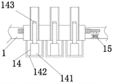
The bottom of carousel is equipped with hoist mechanism, hoist mechanism includes electric telescopic handle, a holding cylinder and pressure sensor, the bottom of carousel is fixed with a holding cylinder, the inner chamber that holds a cylinder is fixed with electric telescopic handle, electric telescopic handle's upper end is located the inner chamber of placing a cylinder and its upper end is fixed with pressure sensor, be fixed with light emitter on placing a cylinder's the inner chamber wall, it is equipped with light receiver and light emitter's axle center on the opposite face that is located the light emitter in the section of thick bamboo to place is located same straight line.
The further improved scheme in the technical scheme is as follows:
1. in the scheme, the lower end of the lower pressing rod is fixedly provided with the rubber pad.
2. In the above scheme, the placing cylinders are uniformly arranged at equal intervals on the circumference by taking the axis of the turntable as the circle center.
3. In the above scheme, the gear on the output shaft of the rotating motor is meshed with the outer wall of the rotary disc.
4. In the above scheme, the longitudinal driving mechanism comprises a longitudinal driving motor, a longitudinal screw rod and a longitudinal nut, the longitudinal driving motor is arranged on the support top plate, an output shaft of the longitudinal driving motor penetrates through the support top plate and is fixedly connected with the upper end of the longitudinal screw rod, the lower end of the longitudinal screw rod penetrates through the containing box and is rotatably connected with the transverse plate, and the longitudinal nut is sleeved on the longitudinal screw rod and is fixedly connected with the containing box. The rod body mechanism 12 can be driven by the longitudinal driving mechanism 7 to carry out lifting motion
5. In the above scheme, the transverse driving mechanism comprises a transverse driving motor, a transverse screw rod and a transverse nut, the transverse driving motor is installed on the outer wall of the containing box, the transverse screw rod is rotatably arranged in the inner cavity of the containing box, one end of the transverse screw rod penetrates through the containing box and is fixedly connected with an output shaft of the transverse driving motor, the other end of the transverse screw rod is rotatably connected with the inner wall of the containing box, and the transverse nut is sleeved on the transverse screw rod and is fixedly connected with the rod body mechanism. The rod body mechanism 12 can be driven to move transversely by the transverse driving mechanism 13
6. In the above scheme, one end of the first rod body is fixedly connected with the transverse nut of the transverse driving mechanism.
7. In the above scheme, the workbench is provided with a controller.
Due to the application of the technical scheme, compared with the prior art, the invention has the following advantages:
1. the chip positioning device for the smart phone is characterized in that a rod body mechanism is provided with a pressing mechanism, a chip moves to an inner cavity of a chip groove formed in a card by utilizing a transverse driving mechanism and a longitudinal driving mechanism, the chip is separated from a rubber sucker by utilizing the pressing mechanism, the chip is compacted and firmly fixed in the chip groove, and therefore the chip is quickly positioned.
2. The chip positioning device for the smart phone is provided with the chip lifting mechanism, the photoelectric switch is formed by the optical receiver and the optical transmitter, the electric telescopic rod is controlled to work by the controller, the output end drives the chip to move upwards until the light emitted by the optical transmitter can be blocked, so that the chip is always kept at a certain height, the descending distance of the rod body is reduced, the time is saved, and the working efficiency is improved.
3. According to the chip positioning device for the smart phone, the rubber pad is arranged at the lower end of the lower pressing rod, so that the buffering effect can be achieved, and the phenomenon that the chip is crushed due to the fact that the pressing distance of the lower pressing rod is too large is avoided.
Detailed Description
In order to make the technical means, the creation characteristics, the achievement purposes and the effects of the invention easy to understand, the invention is further described with the specific embodiments.
In the description of the present invention, it should be noted that the terms "upper", "lower", "inner", "outer", "front", "rear", "both ends", "one end", "the other end", and the like indicate orientations or positional relationships based on those shown in the drawings, and are only for convenience of description and simplicity of description, but do not indicate or imply that the referred device or element must have a specific orientation, be constructed in a specific orientation, and be operated, and thus, should not be construed as limiting the present invention. Furthermore, the terms "first" and "second" are used for descriptive purposes only and are not to be construed as indicating or implying relative importance.
In the description of the present invention, it should be noted that, unless explicitly stated or limited otherwise, the terms "mounted," "disposed," "connected," and the like are to be construed broadly, such as "connected," which may be fixedly connected, detachably connected, or integrally connected; can be mechanically or electrically connected; they may be connected directly or indirectly through intervening media, or they may be interconnected between two elements. The specific meanings of the above terms in the present invention can be understood in specific cases to those skilled in the art.
Example 1: a chip positioning device for a smart phone comprises a workbench 1, a support 5, a longitudinal driving mechanism 7, a containing box 8, a transverse driving mechanism 13 and a rod body mechanism 12, wherein the support 5 is arranged on the upper surface of the workbench 1, the containing box 8 is slidably arranged on the support 5, a transverse plate 9 is arranged below the top plate of the support 5, the longitudinal driving mechanism 7 is positioned between the top plate of the support 5 and the transverse plate 9, the longitudinal driving mechanism 7 penetrates through the containing box 8 and is fixedly connected with the containing box 8, the transverse driving mechanism 13 is arranged in an inner cavity of the containing box 8, the transverse driving mechanism 13 is fixedly connected with the rod body mechanism 12, a chain plate conveying belt 3 is arranged below the transverse plate 9 of the support 5, and a plurality of placing grooves 19 for embedding cards are formed in the chain plate conveying belt 3;
the automatic feeding device is characterized in that a shell 11 is arranged on the rod body mechanism 12, a pressing mechanism 17 is fixed in an inner cavity of the shell 11, a sucking mechanism 18 is installed in the inner cavity of the rod body mechanism 12, a rotary table 2 is rotatably arranged below the rod body mechanism 12, a plurality of placing cylinders 4 are arranged on the rotary table 2, a rotating motor 15 is arranged in the inner cavity of the workbench 1, and an output shaft of the rotating motor 15 is connected with the rotary table 2 and used for driving the rotary table 2 to rotate;
the rod mechanism 12 further includes a first rod 121, a bearing 122 and a second rod 123, the first rod 121 and the second rod 123 are connected through the bearing 122, one end of the first rod 121 is fixedly connected with the transverse driving mechanism 13, the other end of the first rod 121 is fixedly connected with an outer ring of the bearing 122, one end of the bearing 122 opposite to the first rod 121 is connected with the second rod 123, the second rod 123 is fixedly connected with an inner ring of the bearing 122, the housing 11 is disposed at the upper end of the second rod 123 and serves as a carrier for the suction mechanism 18, the pressing mechanism 17, the adjustment motor 20 and the cylinder 6;
an adjusting motor 20 is fixedly arranged in the inner cavity of the first rod body 121, a cylinder 6 is fixedly arranged on an output shaft of the adjusting motor 20, one end of the cylinder 6, which is opposite to the adjusting motor 20, is fixedly connected with an inner ring of the bearing 122, and the angle of the second rod body 123 can be changed through the adjusting motor 20;
the sucking mechanism 18 further comprises a vacuum sucking pump 181, a sucking pipe 182 and a rubber sucker 183, the vacuum sucking pump 181 is located in the cylinder 6, one end of the sucking pipe 182 is connected with the vacuum sucking pump 181, the other end of the sucking pipe 182 extends to the inner cavity of the second rod 123 and extends to the lower part of the second rod 123 through the inner cavity wall of the second rod 123, the rubber sucker 183 is fixed on the outer wall of the lower end of the sucking pipe 182, and the chip can be sucked by the sucking mechanism 18;
the pressing mechanism 17 further includes a pressing motor 171, a pressing screw 172, a movable lever 173, a pressing nut 174, a fixed plate 175 and a pressing lever 176, the pressing motor 171 is disposed on the upper surface of the housing 11, the fixing plate 175 is located in the inner cavity of the housing 11, a lower screw rod 172 is rotatably arranged between the fixing plate 175 and the housing 11, the upper end of the lower screw rod 172 penetrates through the housing 11 and is fixedly connected with the output end of the lower motor 171, the lower pressing nut 174 is sleeved on the lower pressing screw 172, the movable rod 173 is fixedly connected with the lower pressing nut 174, the lower end of the movable rod 173 penetrates through the fixing plate 175 and extends to the lower part thereof to be fixedly connected with the upper end of the lower pressing rod 176, the lower end of the lower pressing rod 176 penetrates through the upper end surface of the second rod body 123 and the upper end surface of the suction pipe 182 and extends to the inner cavity of the suction pipe 182, so that a chip can be pressed into a chip groove on a card, and the chip can be positioned;
the bottom of the rotating disc 2 is provided with a lifting mechanism 14, the lifting mechanism 14 comprises an electric telescopic rod 141, a containing cylinder 142 and a pressure sensor 143, an accommodating cylinder 142 is fixed at the bottom of the rotary table 2, an electric telescopic rod 141 is fixed in the inner cavity of the accommodating cylinder 142, the upper end of the electric telescopic rod 141 is positioned in the inner cavity of the placing barrel 4 and the upper end thereof is fixed with a pressure sensor 143, can play a role of jacking the chip placed in the placing cylinder 4, facilitate the suction of the suction mechanism 18, the inner cavity wall of the placing barrel 4 is fixed with a light emitter 16, a light receiver is arranged on the right opposite side of the light emitter 16 in the placing barrel 4, the axes of the light receiver and the light emitter 16 are positioned on the same straight line, the light emitter 16 and the light receiver form a photoelectric switch, and the controller 10 changes the working state of the lifting mechanism 14 through the current change of the photoelectric switch.
A rubber pad is fixed at the lower end of the lower pressure rod 176; the placing cylinders 4 are uniformly arranged at equal intervals in a circumference manner by taking the axis of the rotary table 2 as the center of a circle; the gear on the output shaft of the rotating motor 15 is meshed with the outer wall of the turntable 2;
the longitudinal driving mechanism 7 comprises a longitudinal driving motor 71, a longitudinal screw 72 and a longitudinal nut 73, the longitudinal driving motor 71 is arranged on the top plate of the bracket 5, an output shaft of the longitudinal driving motor 71 penetrates through the top plate of the bracket 5 and is fixedly connected with the upper end of the longitudinal screw 72, the lower end of the longitudinal screw 72 penetrates through the accommodating box 8 and is rotatably connected with the transverse plate 9, the longitudinal nut 73 is sleeved on the longitudinal screw 72 and is fixedly connected with the accommodating box 8, and the rod body mechanism 12 can be driven to move up and down through the longitudinal driving mechanism 7.
Example 2: a chip positioning device for a smart phone comprises a workbench 1, a support 5, a longitudinal driving mechanism 7, a containing box 8, a transverse driving mechanism 13 and a rod body mechanism 12, wherein the support 5 is arranged on the upper surface of the workbench 1, the containing box 8 is slidably arranged on the support 5, a transverse plate 9 is arranged below the top plate of the support 5, the longitudinal driving mechanism 7 is positioned between the top plate of the support 5 and the transverse plate 9, the longitudinal driving mechanism 7 penetrates through the containing box 8 and is fixedly connected with the containing box 8, the transverse driving mechanism 13 is arranged in an inner cavity of the containing box 8, the transverse driving mechanism 13 is fixedly connected with the rod body mechanism 12, a chain plate conveying belt 3 is arranged below the transverse plate 9 of the support 5, and a plurality of placing grooves 19 for embedding cards are formed in the chain plate conveying belt 3;
the automatic feeding device is characterized in that a shell 11 is arranged on the rod body mechanism 12, a pressing mechanism 17 is fixed in an inner cavity of the shell 11, a sucking mechanism 18 is installed in the inner cavity of the rod body mechanism 12, a rotary table 2 is rotatably arranged below the rod body mechanism 12, a plurality of placing cylinders 4 are arranged on the rotary table 2, a rotating motor 15 is arranged in the inner cavity of the workbench 1, and an output shaft of the rotating motor 15 is connected with the rotary table 2 and used for driving the rotary table 2 to rotate;
the rod mechanism 12 further includes a first rod 121, a bearing 122 and a second rod 123, the first rod 121 and the second rod 123 are connected through the bearing 122, one end of the first rod 121 is fixedly connected with the transverse driving mechanism 13, the other end of the first rod 121 is fixedly connected with an outer ring of the bearing 122, one end of the bearing 122 opposite to the first rod 121 is connected with the second rod 123, the second rod 123 is fixedly connected with an inner ring of the bearing 122, the housing 11 is disposed at the upper end of the second rod 123 and serves as a carrier for the suction mechanism 18, the pressing mechanism 17, the adjustment motor 20 and the cylinder 6;
an adjusting motor 20 is fixedly arranged in the inner cavity of the first rod body 121, a cylinder 6 is fixedly arranged on an output shaft of the adjusting motor 20, one end of the cylinder 6, which is opposite to the adjusting motor 20, is fixedly connected with an inner ring of the bearing 122, and the angle of the second rod body 123 can be changed through the adjusting motor 20;
the sucking mechanism 18 further comprises a vacuum sucking pump 181, a sucking pipe 182 and a rubber sucker 183, the vacuum sucking pump 181 is located in the cylinder 6, one end of the sucking pipe 182 is connected with the vacuum sucking pump 181, the other end of the sucking pipe 182 extends to the inner cavity of the second rod 123 and extends to the lower part of the second rod 123 through the inner cavity wall of the second rod 123, the rubber sucker 183 is fixed on the outer wall of the lower end of the sucking pipe 182, and the chip can be sucked by the sucking mechanism 18;
the pressing mechanism 17 further includes a pressing motor 171, a pressing screw 172, a movable lever 173, a pressing nut 174, a fixed plate 175 and a pressing lever 176, the pressing motor 171 is disposed on the upper surface of the housing 11, the fixing plate 175 is located in the inner cavity of the housing 11, a lower screw rod 172 is rotatably arranged between the fixing plate 175 and the housing 11, the upper end of the lower screw rod 172 penetrates through the housing 11 and is fixedly connected with the output end of the lower motor 171, the lower pressing nut 174 is sleeved on the lower pressing screw 172, the movable rod 173 is fixedly connected with the lower pressing nut 174, the lower end of the movable rod 173 penetrates through the fixing plate 175 and extends to the lower part thereof to be fixedly connected with the upper end of the lower pressing rod 176, the lower end of the lower pressing rod 176 penetrates through the upper end face of the second rod body 123 and the upper end face of the suction pipe 182 and extends to the inner cavity of the suction pipe 182, so that a chip can be pressed into a chip groove on a card, and the chip can be positioned;
the bottom of the rotating disc 2 is provided with a lifting mechanism 14, the lifting mechanism 14 comprises an electric telescopic rod 141, a containing cylinder 142 and a pressure sensor 143, an accommodating cylinder 142 is fixed at the bottom of the turntable 2, an electric telescopic rod 141 is fixed in an inner cavity of the accommodating cylinder 142, the upper end of the electric telescopic rod 141 is positioned in the inner cavity of the placing barrel 4 and the upper end thereof is fixed with a pressure sensor 143, can play a role of jacking the chip placed in the placing cylinder 4, facilitate the suction of the suction mechanism 18, a light emitter 16 is fixed on the wall of the inner cavity of the placing barrel 4, a light receiver is arranged on the right opposite surface of the light emitter 16 in the placing barrel 4, the axes of the light receiver and the light emitter 16 are positioned on the same straight line, the light emitter 16 and the light receiver form a photoelectric switch, and the controller 10 changes the working state of the lifting mechanism 14 through the current change of the photoelectric switch.
The transverse driving mechanism 13 includes a transverse driving motor 131, a transverse screw 132 and a transverse nut 133, the transverse driving motor 131 is mounted on the outer wall of the accommodating box 8, the transverse screw 132 is rotatably disposed in the inner cavity of the accommodating box 8, one end of the transverse screw 132 penetrates through the accommodating box 8 and is fixedly connected with the output shaft of the transverse driving motor 131, the other end of the transverse screw is rotatably connected with the inner wall of the accommodating box 8, the transverse nut 133 is sleeved on the transverse screw 132 and is fixedly connected with the rod mechanism 12, and the rod mechanism 12 can be driven to move transversely by the transverse driving mechanism 13;
one end of the first rod 121 is fixedly connected to a transverse nut 133 of the transverse driving mechanism 13; the worktable 1 is provided with a controller 10.
When the chip positioning device for the smart phone is adopted, the rod body mechanism is provided with the pressing mechanism, the chip moves to the inner cavity of the chip groove formed in the card by utilizing the transverse driving mechanism and the longitudinal driving mechanism, the chip is separated from the rubber sucker by the pressing mechanism, the chip is compacted and firmly fixed in the chip groove, and therefore the chip is quickly positioned; in addition, the chip lifting mechanism is arranged, a photoelectric switch is formed by the optical receiver and the optical transmitter, the controller controls the electric telescopic rod to work, the output end drives the chip to move upwards to the position where the light emitted by the optical transmitter can be blocked, so that the chip is always kept at a certain height, the descending distance of the rod body is reduced, the time is saved, and the working efficiency is improved; in addition, the lower end of the lower pressing rod is provided with a rubber pad, so that the buffering effect can be achieved, and the phenomenon that the chip is crushed due to the fact that the pressing distance of the lower pressing rod is too large is avoided.
It should be noted that the invention is a chip positioning device for a smart phone, a chain plate conveyor belt 3, a longitudinal driving motor 71, a transverse driving motor 131, an electric telescopic rod 141, a pressure sensor 143, a rotating motor 15, a light emitter 16, a pressing motor 171, a vacuum suction pump 181 and an adjusting motor 20 are all electrically connected with a controller 10, the transverse driving motor 131 drives a rod body to move above a placing cylinder 4 through the operation of a transverse driving mechanism 13, a rubber suction cup 183 is made to abut against the upper surface of a chip in the placing cylinder 4 through the operation of the longitudinal driving motor 71, the controller 10 detects the change of the numerical value of the pressure sensor 143, controls the vacuum suction pump 181 to suck the chip, the sucked rod body returns to the original position through the transverse driving mechanism 13 and the longitudinal driving mechanism 7, and drives a second rod body 123 to rotate through the adjusting motor 20, the rotation angle is ninety degrees, so that the chip is in a vertical state, the chip is contacted with the antenna of the card positioned in the placing groove 19 arranged on the chain plate conveying belt 3 through the transverse driving mechanism 13 and the longitudinal driving mechanism 7, the chip is welded through a welding gun, after the welding is finished, the chip is positioned right above the axle center of the chip groove on the card through the transverse driving mechanism 13, the chip is restored to a horizontal state through the work of the adjusting motor 20, the chip moves downwards through the longitudinal driving mechanism 7 and moves to the inner cavity of the chip groove of the card, the controller 10 controls the vacuum suction pump 181 to stop working, controls the pressing mechanism 17 to work, drives the pressing screw rod 172 to rotate through the working of the pressing motor 171, drives the movable rod 173 to drive the pressing rod 176 to do pressing movement through the pressing nut 174, the lower end of the pressing rod 176 is contacted with the upper surface of the chip, separating the chip from the rubber sucker 183 and pressing the chip into the chip groove on the card, returning the lower pressing rod 176 and the rod body to the initial position, repeating the steps to weld and position the chip on the card on the next group of transport plates on the chain plate transport belt 3, wherein the controller 10 is a PLC controller, realizing the automatic processing of the equipment through programming, the inner cavity provided with the placing groove 19 is provided with an electric telescopic rod 141, a photoelectric switch is formed by the light emitter 16 and the light receiver, when the light emitted by the light emitter 16 is received by the light receiver, no chip exists between the front light emitter 16 and the light receiver, the controller 10 detects the current change, and the pressure sensor 143 has a pressure value, the controller 10 controls the electric telescopic rod 141 to work, so that the output end drives the chip to move upwards to stop the light emitted by the light emitter 16, thereby make the chip remain a certain height all the time, be convenient for absorb the absorption of mechanism 18, when pressure sensor 143 did not detect the pressure value of leading, then prove to place the chip in a section of thick bamboo 4 and used up, controller 10 control rotation motor 15 work this moment, drive carousel 2 and rotate certain angle, make next a set of inner chamber be equipped with placing a section of thick bamboo 4 of chip provide the chip for the welding, the artificial mode of accessible is regularly to placing the chip in placing a section of thick bamboo 4, the lower extreme of depression bar 176 is equipped with the rubber pad, can play the effect of buffering, avoid depression bar 176 to push down the distance too big, lead to crushing the chip.
The above embodiments are merely illustrative of the technical ideas and features of the present invention, and the purpose thereof is to enable those skilled in the art to understand the contents of the present invention and implement the present invention, and not to limit the protection scope of the present invention. All equivalent changes and modifications made according to the spirit of the present invention should be covered in the protection scope of the present invention.