CN112690969A - Heart failure patient nursing device - Google Patents
Heart failure patient nursing device Download PDFInfo
- Publication number
- CN112690969A CN112690969A CN202110117513.0A CN202110117513A CN112690969A CN 112690969 A CN112690969 A CN 112690969A CN 202110117513 A CN202110117513 A CN 202110117513A CN 112690969 A CN112690969 A CN 112690969A
- Authority
- CN
- China
- Prior art keywords
- shaped
- inverted
- heart failure
- plate
- waist
- Prior art date
- Legal status (The legal status is an assumption and is not a legal conclusion. Google has not performed a legal analysis and makes no representation as to the accuracy of the status listed.)
- Granted
Links
Images


Classifications
-
- A—HUMAN NECESSITIES
- A61—MEDICAL OR VETERINARY SCIENCE; HYGIENE
- A61G—TRANSPORT, PERSONAL CONVEYANCES, OR ACCOMMODATION SPECIALLY ADAPTED FOR PATIENTS OR DISABLED PERSONS; OPERATING TABLES OR CHAIRS; CHAIRS FOR DENTISTRY; FUNERAL DEVICES
- A61G7/00—Beds specially adapted for nursing; Devices for lifting patients or disabled persons
- A61G7/002—Beds specially adapted for nursing; Devices for lifting patients or disabled persons having adjustable mattress frame
- A61G7/015—Beds specially adapted for nursing; Devices for lifting patients or disabled persons having adjustable mattress frame divided into different adjustable sections, e.g. for Gatch position
-
- A—HUMAN NECESSITIES
- A61—MEDICAL OR VETERINARY SCIENCE; HYGIENE
- A61G—TRANSPORT, PERSONAL CONVEYANCES, OR ACCOMMODATION SPECIALLY ADAPTED FOR PATIENTS OR DISABLED PERSONS; OPERATING TABLES OR CHAIRS; CHAIRS FOR DENTISTRY; FUNERAL DEVICES
- A61G7/00—Beds specially adapted for nursing; Devices for lifting patients or disabled persons
- A61G7/05—Parts, details or accessories of beds
- A61G7/0507—Side-rails
-
- A—HUMAN NECESSITIES
- A61—MEDICAL OR VETERINARY SCIENCE; HYGIENE
- A61H—PHYSICAL THERAPY APPARATUS, e.g. DEVICES FOR LOCATING OR STIMULATING REFLEX POINTS IN THE BODY; ARTIFICIAL RESPIRATION; MASSAGE; BATHING DEVICES FOR SPECIAL THERAPEUTIC OR HYGIENIC PURPOSES OR SPECIFIC PARTS OF THE BODY
- A61H23/00—Percussion or vibration massage, e.g. using supersonic vibration; Suction-vibration massage; Massage with moving diaphragms
- A61H23/006—Percussion or tapping massage
-
- A—HUMAN NECESSITIES
- A61—MEDICAL OR VETERINARY SCIENCE; HYGIENE
- A61H—PHYSICAL THERAPY APPARATUS, e.g. DEVICES FOR LOCATING OR STIMULATING REFLEX POINTS IN THE BODY; ARTIFICIAL RESPIRATION; MASSAGE; BATHING DEVICES FOR SPECIAL THERAPEUTIC OR HYGIENIC PURPOSES OR SPECIFIC PARTS OF THE BODY
- A61H23/00—Percussion or vibration massage, e.g. using supersonic vibration; Suction-vibration massage; Massage with moving diaphragms
- A61H23/02—Percussion or vibration massage, e.g. using supersonic vibration; Suction-vibration massage; Massage with moving diaphragms with electric or magnetic drive
-
- A—HUMAN NECESSITIES
- A61—MEDICAL OR VETERINARY SCIENCE; HYGIENE
- A61H—PHYSICAL THERAPY APPARATUS, e.g. DEVICES FOR LOCATING OR STIMULATING REFLEX POINTS IN THE BODY; ARTIFICIAL RESPIRATION; MASSAGE; BATHING DEVICES FOR SPECIAL THERAPEUTIC OR HYGIENIC PURPOSES OR SPECIFIC PARTS OF THE BODY
- A61H2201/00—Characteristics of apparatus not provided for in the preceding codes
- A61H2201/01—Constructive details
- A61H2201/0119—Support for the device
- A61H2201/0138—Support for the device incorporated in furniture
- A61H2201/0142—Beds
-
- A—HUMAN NECESSITIES
- A61—MEDICAL OR VETERINARY SCIENCE; HYGIENE
- A61H—PHYSICAL THERAPY APPARATUS, e.g. DEVICES FOR LOCATING OR STIMULATING REFLEX POINTS IN THE BODY; ARTIFICIAL RESPIRATION; MASSAGE; BATHING DEVICES FOR SPECIAL THERAPEUTIC OR HYGIENIC PURPOSES OR SPECIFIC PARTS OF THE BODY
- A61H2205/00—Devices for specific parts of the body
- A61H2205/08—Trunk
- A61H2205/081—Back
Abstract
A heart failure patient nursing device effectively solves the problem that medical staff are relatively troublesome to nurse when a heart failure patient has sudden dyspnea; the bed comprises a bed body, wherein a supporting plate is arranged at the upper end of the bed body, inverted L-shaped rods are hinged at four corners of the lower end of the supporting plate, a connecting plate is arranged at the upper ends of two inverted L-shaped rods which are opposite from each other in front and back, a shell is arranged at the lower end of the connecting plate on the left side, a transmission shaft is arranged in the shell, a through groove is formed in the connecting plate on the left side, the lower end of the connecting; the lower ends of the two inverted L-shaped rods which are opposite to each other at the left and right sides are hinged and connected through connecting rods, a fixing rod is arranged between the two connecting rods, the lower end of the supporting plate is provided with a clamping plate, the two clamping plates are rotatably connected with a pin shaft, the pin shaft is coaxially provided with a gear, inverted L-shaped grooves are respectively formed in the opposite ends of the two clamping plates, a rack is connected between the two inverted L-shaped grooves in a sliding manner, and the; the invention has novel conception, ingenious structure, convenient operation and strong practicability.
Description
Technical Field
The invention relates to the technical field of cardiology department nursing instruments, in particular to a heart failure patient nursing device.
Background
Heart failure refers to a clinical syndrome of new insufficiency caused by various heart diseases, and most of the symptoms refer to that the myocardial contractility is reduced, so that the heart discharge capacity cannot meet the requirement of organism metabolism, the blood perfusion of organs and tissues is insufficient, and the pulmonary circulation and the body circulation congestion appear at the same time. With the progress of the disease, the patients have labor dyspnea and paroxysmal dyspnea at night, and the patients need to adopt a semi-lying position at this time, part of blood stays in the lower limbs and the pelvic cavity due to the action of gravity, and the amount of return heart blood is reduced, so that the pulmonary congestion and the cardiac burden are reduced; meanwhile, the diaphragm muscle position can be lowered, the thoracic cavity volume is enlarged, the pressure of visceral organs in the abdominal cavity on the heart and the lung is relieved, the vital capacity is increased, the gas exchange is facilitated, and the symptom of dyspnea is improved.
When heart failure patient proruption breathes the difficulty at present, the nursing staff need assist the patient to sit up, assists the patient to stand up, claps the back simultaneously, does benefit to the sputum and gets rid of, keeps the respiratory track unobstructed, makes the patient inhale oxygen at last, and operating procedure is loaded down with trivial details, and nursing staff nurses and gets up more troublesome, probably can delay the patient's state of an illness, brings the injury for patient's health.
Disclosure of Invention
In view of the above situation, in order to overcome the defects of the prior art, the present invention provides a heart failure patient nursing device, which effectively solves the problem that medical care personnel are more troublesome to nurse when a heart failure patient has sudden dyspnea.
The technical scheme includes that the bed comprises a bed body, a horizontal supporting plate is arranged at the upper end of the bed body, inverted-L-shaped rods are hinged to four corners of the lower end of the supporting plate through front and rear axial rotating shafts respectively, a connecting plate is arranged at the upper ends of the two inverted-L-shaped rods which are opposite to each other in front and rear, a shell is arranged at the lower end of the connecting plate on the left side, a transmission shaft which can rotate in forward and reverse directions is arranged in the shell, through grooves in left and right directions are formed in the front and rear sides of the connecting plate on the left side respectively, swing rods in left and right directions are hinged to the front and rear sides of the lower end of the connecting plate on the left side respectively, the two swing rods can;
control two relative L shape pole lower extremes of falling connect through the connecting rod is articulated, be equipped with fore-and-aft direction's dead lever between two connecting rods, the backup pad lower extreme is equipped with two left right direction and relative splint around, it has a front and back axial round pin axle to rotate on two splint, the round pin axle can rotate along with the transmission shaft, the epaxial straight-teeth gear that is located between two splint of coaxial being equipped with of round pin, the L-shaped groove of falling has been seted up respectively to two splint looks remote site, sliding connection has left right direction and can with the rack of straight-teeth gear meshing between two L-shaped grooves, the rack lower extreme is equipped with the square pole that the.
The nursing bed has the advantages that the conception is novel, the structure is ingenious, the operation is convenient, the practicability is high, the swing rod and the connecting plate are arranged, a nursing person only needs to start the motor to rotate forwards, the swing rod can replace hands of the nursing person to beat the back of the patient through the ball to help the patient with dyspnea to remove sputum and keep the respiratory tract smooth, meanwhile, the patient can be driven to be in a supine state to be in a semi-lying state, the pressure of visceral organs in the abdomen on the heart and the lung is relieved, the vital capacity is increased, the gas exchange is facilitated, the symptoms of dyspnea are improved, the patient can be automatically limited after being in the semi-lying state, the patient can be changed into the supine state again only by contacting the limit and starting the motor to rotate backwards after nursing is.
Drawings
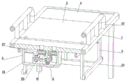
Fig. 1 is an isometric view of the present invention.
FIG. 2 is a front elevational perspective view, in full section, of the present invention.
FIG. 3 is a left side elevational view, in full section, of the present invention.
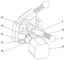
Fig. 4 is a rear perspective view of the rocker, waist plate and waist ring of the present invention.
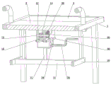
Figure 5 is a left side cutaway isometric view of the present invention.
FIG. 6 is a full section bottom isometric view of the present invention.
FIG. 7 is a right isometric view in full section of the present invention.
Fig. 8 is an isometric view of the open position of the present invention.
Fig. 9 is an enlarged view of a in fig. 3 of the present invention.
Detailed Description
The following describes embodiments of the present invention in further detail with reference to the accompanying drawings.
The bed comprises a bed body 1, a horizontal supporting plate 2 is arranged at the upper end of the bed body 1, four corners of the lower end of the supporting plate 2 are respectively hinged with inverted L-shaped rods 3 through front and rear axial rotating shafts, a connecting plate 4 is arranged at the upper ends of two inverted L-shaped rods 3 which are opposite front and rear, a shell 5 is arranged at the lower end of the connecting plate 4 on the left side, a transmission shaft 6 which can rotate forward and backward is arranged in the shell 5, through grooves 7 in left and right directions are respectively formed in the front and rear sides of the connecting plate 4 on the left side, swing rods 8 in left and right directions are respectively hinged with the front and rear sides of the lower end of the connecting plate 4 on the left side, the two swing rods 8 can swing up and down along with the forward rotation of the transmission shaft 6, the swing directions of the two;
the articulated connection of connecting rod 10 is passed through to two 3 lower extremes of the L shape pole of falling about relative, be equipped with fore-and-aft direction's dead lever 11 between two connecting rods 10, 2 lower extremes of backup pad are equipped with about two directions and relative splint 12 around, it has axial round pin axle 13 around one to rotate on two splint 12, round pin axle 13 can rotate along with transmission shaft 6, the coaxial spur gear 14 that is located between two splint 12 that is equipped with on round pin axle 13, the L shape groove 15 that falls has been seted up respectively to two splint 12 looks remote sites, sliding connection has about the direction and can with the rack 16 of spur gear 14 meshing between two L shape grooves 15 that fall, the rack 16 lower extreme is equipped with the square pole 17 that the up-and-down direction.
In order to enable the transmission shaft 6 to rotate forward and backward, a motor 18 which is positioned behind the transmission shaft 6 and can rotate forward and backward is arranged in the shell 5, and the output end of the motor 18 is coaxially and fixedly connected with the transmission shaft 6.
In order to enable the two swing rods 8 to swing up and down along with the positive rotation of the transmission shaft 6, the front end of the transmission shaft 6 is provided with a swing rod 20 through a one-way bearing 19, opposite ends of the two swing rods 8 are respectively provided with a waist-shaped plate 21 in the vertical direction, a waist-shaped groove is formed in the waist-shaped plate 21, a waist-shaped ring 22 positioned between the two waist-shaped plates 21 is connected in the shell 5 in a sliding manner, front and back sides of the upper end of the waist-shaped ring 22 are respectively provided with a front and back axial insertion column 23, the insertion column 23 is positioned in the waist-shaped groove on the corresponding side, and the free end.
In order to enable the pin shaft 13 to rotate along with the rotation of the transmission shaft 6, the lower end of the support plate 2 is provided with a connecting shaft 25 which is coaxial with the two rotating shafts on the left side, belt wheels 26 are respectively arranged on the connecting shaft 25 and the transmission shaft 6, the two belt wheels 26 are connected through a belt 27, the lower end of the support plate 2 is rotatably connected with a worm 28 which is positioned in the left-right axial direction and in front of the clamping plate 12, the worm 28 and the connecting shaft 25 are respectively provided with bevel gears 29, the two bevel gears 29 are mutually meshed, and the front end of the pin shaft 13 penetrates through the.
In order to enable the rack 16 to be meshed with the straight gear 14, the front end and the rear end of the rack 16 are respectively provided with a sliding rail 31 located in an inverted L-shaped groove 15 on the corresponding side of the rack, the sliding rail 31 can be clamped at the left end of the inverted L-shaped groove 15, the lower ends of the two clamping plates 12 are connected with a box body with an upward opening in a sliding manner, a flat plate 32 connected with the square rod 17 in a sliding manner is arranged in the box body, and the upper end of the flat plate 32 is connected with the rack.
In order to limit the flat plate 32 conveniently, the front end of the box body is provided with a U-shaped groove 34 with an opening facing to the left, and the front end of the flat plate 32 is hinged with a Z-shaped rod 35 extending out of the U-shaped groove 34.
In order to make the box body connected with the two clamping plates 12 in a sliding manner, the two clamping plates 12 are respectively provided with a left-right guide rail 36 at the back end, and the front end and the rear end of the box body are respectively connected with the guide rails 36 at the corresponding sides in a sliding manner.
In order to prevent the patient from falling from the bed body 1, the front end and the rear end of the bed body 1 are respectively provided with a guardrail 37.
When the bed is used, the Z-shaped rod 35 is arranged in an initial state of being clamped at the lower end of the U-shaped groove 34, the tension spring 33 is in a stretching state at the moment, the head of a patient is horizontally laid on the bed body 1 towards the left, the back of the patient is positioned right above the two through grooves 7, the lower leg of the patient is positioned right above the connecting plate 4 on the right side, and the guardrails 37 at the front end and the rear end of the bed body 1 can effectively prevent the patient from falling from the bed body 1;
when a patient has sudden dyspnea, a nursing person can start the motor 18 to rotate positively, the output end of the motor 18 drives the transmission shaft 6 to rotate clockwise, the transmission shaft 6 drives the rocker 20 to rotate clockwise through the one-way bearing 19, the rocker 20 drives the waist-shaped ring 22 to move up and down in a reciprocating manner through the cylindrical rod 24, the waist-shaped ring 22 drives the two inserting columns 23 at the upper end of the waist-shaped ring to slide up and down in the waist-shaped groove, the inserting columns 23 drive the waist-shaped plate 21 to swing left and right in a reciprocating manner, the swinging directions of the two waist-shaped plates 21 are opposite, the two waist-shaped plates 21 drive the two swinging rods 8 to swing up and down in a reciprocating manner, the swinging rods 8 drive the round balls 9 to move up and down through the through grooves 7 on the corresponding sides of the;
the transmission shaft 6 drives the connecting shaft 25 to rotate clockwise through the belt 27 and the belt wheel 26, the connecting shaft 25 drives the worm 28 to rotate anticlockwise through the bevel gear 29, the worm 28 drives the worm wheel 30 to rotate clockwise, the worm wheel 30 drives the straight gear 14 to rotate clockwise through the pin shaft 13, at the moment, the straight gear 14 and the rack 16 are in a meshed state, the straight gear 14 drives the rack 16 to slide leftwards between the two clamping plates 12, the rack 16 drives the fixing rod 11 to move leftwards through the square rod 17, the fixing rod 11 drives the two connecting rods 10 to move leftwards synchronously, the two connecting rods 10 drive the lower ends of the plurality of inverted L-shaped rods 3 to swing leftwards, the left ends of the two inverted L-shaped rods 3 on the left side drive the connecting plate 4 on the left side to swing upwards, the connecting plate 4 on the left side drives the back of a patient to swing upwards;
when the rack 16 slides leftwards, the slide rail 31 is driven to move leftwards in the inverted L-shaped groove 15, when the slide rail 31 moves to the left end of the inverted L-shaped groove 15, the rack 16 moves downwards under the action of the pulling force of the tension spring 33, the slide rail 31 is clamped at the left end of the inverted L-shaped groove 15, the rack 16 is disengaged from the straight gear 14, at the moment, the rack 16 does not move along with the rotation of the straight gear 14, the two connecting plates 4 are fixed at the current position, the body of a patient is changed from a supine state to a semi-recumbent state, the dyspnea symptom of the patient is relieved, and a nursing worker only needs;
after the dyspnea symptom of a patient is eliminated, a nursing staff can firstly close the motor 18, clamp the Z-shaped rod 35 at the upper end of the U-shaped groove 34, the Z-shaped rod 35 drives the flat plate 32 to move upwards, the tension spring 33 between the flat plate 32 and the rack 16 is changed from a tension state to a compression state, the rack 16 is moved upwards under the action of elastic force and is re-meshed with the straight gear 14, the rack 16 drives the sliding rail 31 to slide out of the left end of the inverted L-shaped groove 15 upwards, due to the self-locking property between the worm wheel 30 and the worm 28, the two connecting plates 4 cannot swing automatically, then the motor 18 is started to rotate reversely, the output end of the motor 18 drives the transmission shaft 6 to rotate anticlockwise, at the moment, the one-way bearing;
the transmission shaft 6 drives the connecting shaft 25 to rotate anticlockwise through the belt 27 and the belt wheel 26, the connecting shaft 25 drives the worm 28 to rotate clockwise through the bevel gear 29, the worm 28 drives the straight gear 14 to rotate anticlockwise through the worm wheel 30 and the pin shaft 13, the straight gear 14 drives the rack 16 to move rightwards, the rack 16 drives the two connecting rods 10 to move rightwards through the square rod 17 and the fixing rod 11, the connecting rods 10 drive the lower ends of the inverted L-shaped rods 3 to swing rightwards, the two L-shaped rods on the left side drive the back of a patient to swing downwards through the connecting plate 4, the two L-shaped rods on the right side drive the shanks of the patient to swing upwards through the connecting plate 4 until the patient changes from a semi-.
The utility model provides a motor 18 and the one-way bearing 19 that can just reverse are prior art, and here is no longer described its structure in detail.
The nursing bed has the advantages that the conception is novel, the structure is ingenious, the operation is convenient, the practicability is high, the swing rod and the connecting plate are arranged, a nursing person only needs to start the motor to rotate forwards, the swing rod can replace hands of the nursing person to beat the back of the patient through the ball to help the patient with dyspnea to remove sputum and keep the respiratory tract smooth, meanwhile, the patient can be driven to be in a supine state to be in a semi-lying state, the pressure of visceral organs in the abdomen on the heart and the lung is relieved, the vital capacity is increased, the gas exchange is facilitated, the symptoms of dyspnea are improved, the patient can be automatically limited after being in the semi-lying state, the patient can be changed into the supine state again only by contacting the limit and starting the motor to rotate backwards after nursing is.
Therefore, the heart failure patient nursing device provided by the invention can effectively solve the problem that nursing of medical staff is troublesome when a heart failure patient suddenly breathes difficultly, is simple in structure and operation and convenient to use, and improves nursing efficiency of the nursing staff.
Claims (8)
1. A heart failure patient nursing device comprises a bed body (1) and is characterized in that a horizontal supporting plate (2) is arranged at the upper end of the bed body (1), four corners of the lower end of the supporting plate (2) are respectively hinged with inverted L-shaped rods (3) through front and rear axial rotating shafts, a connecting plate (4) is arranged at the upper ends of the two inverted L-shaped rods (3) which are opposite in front and rear, a shell (5) is arranged at the lower end of the left connecting plate (4), a transmission shaft (6) which can rotate forward and backward is arranged in the shell (5), through grooves (7) in left and right directions are respectively arranged at the front and rear sides of the left connecting plate (4), swing rods (8) in left and right directions are respectively hinged at the front and rear sides of the lower end of the left connecting plate (4), the two swing rods (8) can swing up and down along with the forward rotation, the two round balls (9) can respectively extend out of the through grooves (7) on the corresponding sides;
control relative two inverted L shape pole (3) lower extreme connect through connecting rod (10) are articulated, be equipped with fore-and-aft direction's dead lever (11) between two connecting rod (10), backup pad (2) lower extreme is equipped with about two direction and around relative splint (12), it is connected with axial round pin axle (13) around one to rotate on two splint (12), round pin axle (13) can rotate and rotate along with transmission shaft (6), coaxial straight-teeth gear (14) that are located between two splint (12) of being equipped with on round pin axle (13), inverted L shape groove (15) have been seted up respectively to two splint (12) looks remote site, sliding connection has about between two inverted L shape grooves (15) rack (16) that direction just can mesh with straight-teeth gear (14), rack (16) lower extreme is equipped with square pole (17) that the up-down direction just runs through dead lever (11).
2. The heart failure patient nursing device according to claim 1, wherein a motor (18) which is located behind the transmission shaft (6) and can rotate forward and backward is arranged in the housing (5), and the output end of the motor (18) is coaxially and fixedly connected with the transmission shaft (6).
3. The heart failure patient nursing device according to claim 1, wherein the front end of the transmission shaft (6) is provided with a rocker (20) through a one-way bearing 19, the opposite ends of the two rockers (8) are respectively provided with a waist-shaped plate (21) in the up-down direction, a waist-shaped groove is formed in the waist-shaped plate (21), a waist-shaped ring (22) positioned between the two waist-shaped plates (21) is slidably connected in the housing (5), the front side and the rear side of the upper end of the waist-shaped ring (22) are respectively provided with a front axial insertion column (23) and a rear axial insertion column (23) are positioned in the waist-shaped groove on the corresponding side of the waist-shaped ring, and the free end of the rocker (20) is provided with.
4. The heart failure patient nursing device according to claim 1, wherein the lower end of the support plate (2) is provided with a connecting shaft (25) coaxial with the two rotating shafts on the left side, the connecting shaft (25) and the transmission shaft (6) are respectively provided with a belt wheel (26), the two belt wheels (26) are connected through a belt (27), the lower end of the support plate (2) is rotatably connected with a worm (28) which is positioned in front of the clamping plate (12) in the left-right axial direction, the worm (28) and the connecting shaft (25) are respectively provided with a bevel gear (29), the two bevel gears (29) are meshed with each other, and the front end of the pin shaft (13) penetrates through the clamping plate (12) and is coaxially provided with a worm wheel (30) meshed.
5. The heart failure patient nursing device according to claim 1, wherein the front and rear ends of the rack (16) are respectively provided with a slide rail (31) in the inverted L-shaped groove (15) on the corresponding side, the slide rail (31) can be clamped at the left end of the inverted L-shaped groove (15), the lower ends of the two clamping plates (12) are slidably connected with a box body with an upward opening, a flat plate (32) slidably connected with the square rod (17) is arranged in the box body, and the upper end of the flat plate (32) is connected with the rack (16) through a tension spring (33).
6. The heart failure patient nursing device according to claim 1, wherein the front end of the box body is provided with a U-shaped slot (34) with an opening facing to the left, and the front end of the flat plate (32) is hinged with a Z-shaped rod (35) extending out of the U-shaped slot (34).
7. The heart failure patient nursing device according to claim 1, wherein the opposite ends of the two splints (12) are respectively provided with a left-right guide rail (36), and the front and rear ends of the box body are respectively connected with the guide rails (36) on the corresponding sides in a sliding manner.
8. The nursing device for heart failure patients as claimed in claim 1, wherein the bed (1) is provided with guard rails (37) at the front and rear ends thereof.
Applications Claiming Priority (2)
| Application Number | Priority Date | Filing Date | Title |
|---|---|---|---|
| CN2020115774049 | 2020-12-28 | ||
| CN202011577404 | 2020-12-28 |
Publications (2)
| Publication Number | Publication Date |
|---|---|
| CN112690969A true CN112690969A (en) | 2021-04-23 |
| CN112690969B CN112690969B (en) | 2022-03-15 |
Family
ID=75516310
Family Applications (1)
| Application Number | Title | Priority Date | Filing Date |
|---|---|---|---|
| CN202110117513.0A Active CN112690969B (en) | 2020-12-28 | 2021-01-28 | Heart failure patient nursing device |
Country Status (1)
| Country | Link |
|---|---|
| CN (1) | CN112690969B (en) |
Cited By (2)
| Publication number | Priority date | Publication date | Assignee | Title |
|---|---|---|---|---|
| CN113057723A (en) * | 2021-05-06 | 2021-07-02 | 河南科技大学第一附属医院 | Spinal canal anesthesia auxiliary device |
| CN115252307A (en) * | 2022-06-21 | 2022-11-01 | 山西医科大学第二医院 | Auxiliary breathing device based on cardiac failure patient uses |
Citations (10)
| Publication number | Priority date | Publication date | Assignee | Title |
|---|---|---|---|---|
| US20120209157A1 (en) * | 2009-10-23 | 2012-08-16 | Jean-Jacques Racine | Massage Table for Recumbent or Seated Person |
| CN104146841A (en) * | 2014-09-05 | 2014-11-19 | 常州工学院 | Multifunctional massage bed for caring patient through manually lifting back and bending legs |
| US20150190306A1 (en) * | 2013-12-11 | 2015-07-09 | Ergomotion, Inc. | Vibratory system for massage and audio generation in an articulating bed |
| CN106361512A (en) * | 2016-10-10 | 2017-02-01 | 遵义医学院附属医院 | Novel nursing bed for cardiology department |
| CN106667716A (en) * | 2016-08-03 | 2017-05-17 | 山东建筑大学 | Transformable multi-functional massage chair |
| CN109481184A (en) * | 2018-12-29 | 2019-03-19 | 广州医软智能科技有限公司 | A kind of intensive care patient bed and its control method with bat back function |
| CN211156819U (en) * | 2019-11-25 | 2020-08-04 | 青岛大学附属医院 | Lifting device for internal medicine nursing |
| CN111759690A (en) * | 2020-07-27 | 2020-10-13 | 上海荣泰健康科技股份有限公司 | Massage chair with link gear |
| CN111870449A (en) * | 2020-09-09 | 2020-11-03 | 南阳医学高等专科学校第一附属医院 | Liquid food feeding device for nursing in critical medicine department |
| CN112006823A (en) * | 2020-09-09 | 2020-12-01 | 南阳市中心医院 | Orthopedic traction bed |
-
2021
- 2021-01-28 CN CN202110117513.0A patent/CN112690969B/en active Active
Patent Citations (10)
| Publication number | Priority date | Publication date | Assignee | Title |
|---|---|---|---|---|
| US20120209157A1 (en) * | 2009-10-23 | 2012-08-16 | Jean-Jacques Racine | Massage Table for Recumbent or Seated Person |
| US20150190306A1 (en) * | 2013-12-11 | 2015-07-09 | Ergomotion, Inc. | Vibratory system for massage and audio generation in an articulating bed |
| CN104146841A (en) * | 2014-09-05 | 2014-11-19 | 常州工学院 | Multifunctional massage bed for caring patient through manually lifting back and bending legs |
| CN106667716A (en) * | 2016-08-03 | 2017-05-17 | 山东建筑大学 | Transformable multi-functional massage chair |
| CN106361512A (en) * | 2016-10-10 | 2017-02-01 | 遵义医学院附属医院 | Novel nursing bed for cardiology department |
| CN109481184A (en) * | 2018-12-29 | 2019-03-19 | 广州医软智能科技有限公司 | A kind of intensive care patient bed and its control method with bat back function |
| CN211156819U (en) * | 2019-11-25 | 2020-08-04 | 青岛大学附属医院 | Lifting device for internal medicine nursing |
| CN111759690A (en) * | 2020-07-27 | 2020-10-13 | 上海荣泰健康科技股份有限公司 | Massage chair with link gear |
| CN111870449A (en) * | 2020-09-09 | 2020-11-03 | 南阳医学高等专科学校第一附属医院 | Liquid food feeding device for nursing in critical medicine department |
| CN112006823A (en) * | 2020-09-09 | 2020-12-01 | 南阳市中心医院 | Orthopedic traction bed |
Cited By (2)
| Publication number | Priority date | Publication date | Assignee | Title |
|---|---|---|---|---|
| CN113057723A (en) * | 2021-05-06 | 2021-07-02 | 河南科技大学第一附属医院 | Spinal canal anesthesia auxiliary device |
| CN115252307A (en) * | 2022-06-21 | 2022-11-01 | 山西医科大学第二医院 | Auxiliary breathing device based on cardiac failure patient uses |
Also Published As
| Publication number | Publication date |
|---|---|
| CN112690969B (en) | 2022-03-15 |
Similar Documents
| Publication | Publication Date | Title |
|---|---|---|
| CN112690969B (en) | Heart failure patient nursing device | |
| CN107736977A (en) | A kind of adjustable examination couch of obstetrics | |
| CN111265312B (en) | Auxiliary support for anesthesia | |
| CN114983761A (en) | Rehabilitation exercise device after interventional therapy of cardiology | |
| CN110974601A (en) | Rehabilitation exercise device for interventional nursing | |
| CN112057256B (en) | Hemodialysis auxiliary nursing device | |
| CN110465049A (en) | A kind of Internal Medicine-Cardiovascular Dept. Chinese medicine rehabilitation health care devices | |
| CN109125010A (en) | A kind of Gastroenterology dept.'s gastrointestinal disease patient physical therapy intelligent massaging mechanical arm | |
| CN110638618A (en) | Uropoiesis surgery nursing device | |
| CN111513983A (en) | Cardiovascular internal medicine disease rehabilitation physiotherapy device | |
| CN211885190U (en) | Device is tempered in nursing of intervention postoperative limbs | |
| CN110787021A (en) | Limiting bed for retention enema of traditional Chinese medicine decoction | |
| CN211797545U (en) | Multifunctional treatment bed | |
| CN108042303A (en) | A kind of gynicologycal medical motor-driven operating table | |
| CN211243566U (en) | Interventional department pressurization nursing device | |
| CN207384468U (en) | Recovery of paralytic patient auxiliary trainer | |
| CN113749875B (en) | Limb fixing device for nursing in cardiothoracic surgery | |
| CN206896465U (en) | A kind of cardiovascular and cerebrovascular nursing device | |
| CN220404358U (en) | Gynaecology and obstetrics's nursing frame | |
| CN213941235U (en) | Department of general surgery is with multi-functional nursing bed | |
| CN213311399U (en) | Orthopedics rehabilitation and nursing equipment | |
| CN218529116U (en) | Auxiliary tool for getting on and off bed | |
| CN215875305U (en) | Getting-up assisting bed for rehabilitation | |
| CN114533434A (en) | Intracardiac branch of academic or vocational study intervention postoperative limbs nursing device | |
| CN212700328U (en) | Horizontal lower limb rehabilitation device for coronary heart disease patient |
Legal Events
| Date | Code | Title | Description |
|---|---|---|---|
| PB01 | Publication | ||
| PB01 | Publication | ||
| SE01 | Entry into force of request for substantive examination | ||
| SE01 | Entry into force of request for substantive examination | ||
| GR01 | Patent grant | ||
| GR01 | Patent grant |