CN111870449A - Liquid food feeding device for nursing in critical medicine department - Google Patents
Liquid food feeding device for nursing in critical medicine department Download PDFInfo
- Publication number
- CN111870449A CN111870449A CN202010942336.5A CN202010942336A CN111870449A CN 111870449 A CN111870449 A CN 111870449A CN 202010942336 A CN202010942336 A CN 202010942336A CN 111870449 A CN111870449 A CN 111870449A
- Authority
- CN
- China
- Prior art keywords
- gear
- fixedly connected
- rod
- plate
- coaxially
- Prior art date
- Legal status (The legal status is an assumption and is not a legal conclusion. Google has not performed a legal analysis and makes no representation as to the accuracy of the status listed.)
- Withdrawn
Links
Images


Classifications
-
- A—HUMAN NECESSITIES
- A61—MEDICAL OR VETERINARY SCIENCE; HYGIENE
- A61G—TRANSPORT, PERSONAL CONVEYANCES, OR ACCOMMODATION SPECIALLY ADAPTED FOR PATIENTS OR DISABLED PERSONS; OPERATING TABLES OR CHAIRS; CHAIRS FOR DENTISTRY; FUNERAL DEVICES
- A61G7/00—Beds specially adapted for nursing; Devices for lifting patients or disabled persons
- A61G7/002—Beds specially adapted for nursing; Devices for lifting patients or disabled persons having adjustable mattress frame
- A61G7/015—Beds specially adapted for nursing; Devices for lifting patients or disabled persons having adjustable mattress frame divided into different adjustable sections, e.g. for Gatch position
-
- A—HUMAN NECESSITIES
- A61—MEDICAL OR VETERINARY SCIENCE; HYGIENE
- A61G—TRANSPORT, PERSONAL CONVEYANCES, OR ACCOMMODATION SPECIALLY ADAPTED FOR PATIENTS OR DISABLED PERSONS; OPERATING TABLES OR CHAIRS; CHAIRS FOR DENTISTRY; FUNERAL DEVICES
- A61G7/00—Beds specially adapted for nursing; Devices for lifting patients or disabled persons
- A61G7/002—Beds specially adapted for nursing; Devices for lifting patients or disabled persons having adjustable mattress frame
- A61G7/018—Control or drive mechanisms
-
- A—HUMAN NECESSITIES
- A61—MEDICAL OR VETERINARY SCIENCE; HYGIENE
- A61G—TRANSPORT, PERSONAL CONVEYANCES, OR ACCOMMODATION SPECIALLY ADAPTED FOR PATIENTS OR DISABLED PERSONS; OPERATING TABLES OR CHAIRS; CHAIRS FOR DENTISTRY; FUNERAL DEVICES
- A61G7/00—Beds specially adapted for nursing; Devices for lifting patients or disabled persons
- A61G7/05—Parts, details or accessories of beds
- A61G7/053—Aids for getting into, or out of, bed, e.g. steps, chairs, cane-like supports
-
- A—HUMAN NECESSITIES
- A61—MEDICAL OR VETERINARY SCIENCE; HYGIENE
- A61G—TRANSPORT, PERSONAL CONVEYANCES, OR ACCOMMODATION SPECIALLY ADAPTED FOR PATIENTS OR DISABLED PERSONS; OPERATING TABLES OR CHAIRS; CHAIRS FOR DENTISTRY; FUNERAL DEVICES
- A61G7/00—Beds specially adapted for nursing; Devices for lifting patients or disabled persons
- A61G7/05—Parts, details or accessories of beds
- A61G7/065—Rests specially adapted therefor
- A61G7/07—Rests specially adapted therefor for the head or torso, e.g. special back-rests
-
- A—HUMAN NECESSITIES
- A61—MEDICAL OR VETERINARY SCIENCE; HYGIENE
- A61H—PHYSICAL THERAPY APPARATUS, e.g. DEVICES FOR LOCATING OR STIMULATING REFLEX POINTS IN THE BODY; ARTIFICIAL RESPIRATION; MASSAGE; BATHING DEVICES FOR SPECIAL THERAPEUTIC OR HYGIENIC PURPOSES OR SPECIFIC PARTS OF THE BODY
- A61H23/00—Percussion or vibration massage, e.g. using supersonic vibration; Suction-vibration massage; Massage with moving diaphragms
- A61H23/006—Percussion or tapping massage
-
- A—HUMAN NECESSITIES
- A61—MEDICAL OR VETERINARY SCIENCE; HYGIENE
- A61H—PHYSICAL THERAPY APPARATUS, e.g. DEVICES FOR LOCATING OR STIMULATING REFLEX POINTS IN THE BODY; ARTIFICIAL RESPIRATION; MASSAGE; BATHING DEVICES FOR SPECIAL THERAPEUTIC OR HYGIENIC PURPOSES OR SPECIFIC PARTS OF THE BODY
- A61H23/00—Percussion or vibration massage, e.g. using supersonic vibration; Suction-vibration massage; Massage with moving diaphragms
- A61H23/02—Percussion or vibration massage, e.g. using supersonic vibration; Suction-vibration massage; Massage with moving diaphragms with electric or magnetic drive
-
- A—HUMAN NECESSITIES
- A61—MEDICAL OR VETERINARY SCIENCE; HYGIENE
- A61G—TRANSPORT, PERSONAL CONVEYANCES, OR ACCOMMODATION SPECIALLY ADAPTED FOR PATIENTS OR DISABLED PERSONS; OPERATING TABLES OR CHAIRS; CHAIRS FOR DENTISTRY; FUNERAL DEVICES
- A61G2210/00—Devices for specific treatment or diagnosis
- A61G2210/30—Devices for specific treatment or diagnosis for intensive care
Abstract
A liquid food feeder for nursing in the critical medicine department comprises a bedstead, wherein a fixed bed plate is fixedly connected to the rear side of the top of the bedstead, a movable bed plate capable of swinging back and forth is arranged on the front side of the top of the bedstead, a suspension rod capable of swinging back and forth and stretching along with the swinging of the movable bed plate is arranged at the side end of the front part of the bedstead, a suspension frame capable of swinging back and forth is arranged at the top of the suspension rod, and two clamping pieces capable of moving left and right relatively are arranged at the bottom of the suspension frame; the top of the movable bed plate is provided with a rising plate which can swing back and forth, the left side and the right side of the center of the top of the rising plate are respectively provided with a sliding plate, and the front side and the rear side of the top of the sliding plate are respectively provided with a bowl-shaped back knocking bowl; the rising plate swings backwards to the limit position to form a structure that the sliding plate reciprocates up and down and the back bowl is knocked to reciprocate back and forth. The invention effectively solves the problems of low nursing efficiency, manual back-beating of the patient when the patient gets up to increase the nursing workload of medical care personnel and high danger coefficient existing in the prior liquid diet feeding of the critical medicine department.
Description
Technical Field
The invention belongs to the field of medical instruments, and particularly relates to a liquid food feeder for nursing in a critical medicine department.
Background
After the heart operation, the functions of the heart, the lung, the kidney, the brain and the like of a patient are in an unstable state, abnormal changes are found in time through monitoring, advanced medical technology and equipment are applied to immediately correct, various abnormal indexes are rapidly recovered to a normal range, the functions of all internal organs of the patient are ensured to be in a stable state, and the patient is allowed to pass through a dangerous stage.
After a patient enters a monitoring room after a surgery, medical staff needs to be quickly connected with a breathing machine, an electrocardio monitoring line, an artery pressure measuring device, a central venous pressure pipe, a catheter, a stomach tube, an infusion pump and the like. The leads and the pipelines are important pipelines for monitoring and maintaining life, and patients need to be closely matched and cannot be pulled out automatically, so that accidents are avoided, and the life of the patients is endangered.
The guardianship room is directly related to the safety and the rehabilitation of the surgical patients, and is one of the key links for improving the success rate of the surgical operation.
Liquid diet feeding is also one of the necessary work of a heart monitoring room, but the liquid diet feeding risk is high, choking is easy to occur, and the trachea can be blocked seriously, so that the life of a patient is threatened.
At present, no special device for assisting liquid diet feeding exists, so that the back of a patient needs to be manually lifted during liquid diet feeding, and the operation is inconvenient; when the patient is choked, the patient needs to be held to a sitting position by medical staff and is patted back by holding the patient, so that the nursing workload is not increased for the medical staff, and the danger coefficient is high.
Disclosure of Invention
Aiming at the defects of the prior art, the invention provides the liquid diet feeder for nursing the critical medical department, which effectively solves the problems that the nursing efficiency is low, the nursing workload of medical care personnel is increased by manually beating the back of a patient when a patient is choked to cough, and the danger coefficient is high when the liquid diet feeder for nursing the critical medical department at present is used for feeding the critical medical department.
In order to solve the problems, the invention adopts the technical scheme that:
a liquid food feeder for nursing in the critical medicine department comprises a bedstead, wherein a fixed bed plate is fixedly connected to the rear side of the top of the bedstead, a movable bed plate capable of swinging back and forth is arranged on the front side of the top of the bedstead, a suspension rod capable of swinging back and forth and stretching along with the swinging of the movable bed plate is arranged at the side end of the front part of the bedstead, a suspension frame capable of swinging back and forth is arranged at the top of the suspension rod, and two clamping pieces capable of moving left and right relatively are arranged at the bottom of the suspension frame;
the top of the movable bed plate is provided with a rising plate which can swing back and forth, the left side and the right side of the center of the top of the rising plate are respectively provided with a sliding plate, and the front side and the rear side of the top of the sliding plate are respectively provided with a bowl-shaped back knocking bowl; the lifting plate swings backwards to the extreme position to form a structure that the sliding plate reciprocates up and down and the back knocking bowl reciprocates back and forth;
the left side and the right side of the top of the rising plate are respectively provided with a binding band, and the tail ends of the binding bands are respectively provided with a connecting buckle.
Preferably, the rear end of the movable bed plate is hinged with the fixed bed plate, the bottom of the bed frame is fixedly connected with a first motor, a shaft of the first motor is coaxially and fixedly connected with a worm, and the worm is meshed with a worm wheel; the worm wheel and the worm are both rotationally connected to the bottom of the bedstead; the worm wheel is fixedly connected with a support disc, a support rod is hinged to the non-circle center position of the end face of the support disc, and the top of the support rod is hinged to the middle of the bottom end of the movable bed plate.
Preferably, the worm wheel is coaxially and fixedly connected with an incomplete inner gear ring, and the end face of the incomplete inner gear ring is coaxially and fixedly connected with an incomplete outer gear;
the bottom of the bedstead is rotatably connected with a bidirectional gear, and the worm gear rotates for a circle to form a structure that the incomplete inner gear ring and the incomplete outer gear are respectively meshed with the bidirectional gear; the incomplete inner gear ring and the incomplete outer gear are respectively meshed with the bidirectional gear to form a structure that the bidirectional gear rotates positively and negatively.
Preferably, the bidirectional gear is coaxially and fixedly connected with a driving plate, the driving plate is matched with a grooved wheel, the grooved wheel is rotatably connected to the bottom of the bedstead, and the driving plate and the grooved wheel are matched to form a grooved wheel mechanism;
the grooved pulley is coaxially and fixedly connected with a driving gear, the driving gear is meshed with an idler, and the idler is rotatably connected to the upper part of the bedstead;
the bottom end of the suspension rod is fixedly connected with a rotating shaft, and the suspension rod is rotatably connected to the upper part of the bedstead through the rotating shaft; the rotating shaft is coaxially and fixedly connected with a driven gear, and the driven gear is meshed with the idle wheel.
Preferably, the tail end of the suspension rod is provided with a sliding hole, a telescopic rod is connected in the sliding hole in a sliding manner, the top end of the telescopic rod is rotatably connected with the suspension frame, and the bottom end of the telescopic rod is fixedly connected with a turning rod;
the front part of the tail end of the turning rod is hinged with a pull rod capable of swinging back and forth, the front end of the pull rod is hinged with a pull seat, and the pull seat is fixedly connected to the upper part of the bedstead on the front side of the suspension rod.
Preferably, the top of the suspension bracket is rotatably connected with a clamping screw; the clamping screw is coaxially and fixedly connected with a clamping rotating wheel; the clamping screw is in threaded connection with a clamping screw block, the left side and the right side of the clamping screw block are respectively hinged with a clamping rod, and the tail end of each clamping rod is respectively hinged with a clamping piece at a corresponding position;
the front side and the rear side of the top of the clamping piece are respectively connected with clamping slide bars in a sliding manner, and the clamping slide bars are fixedly connected to the bottom of the suspension bracket;
one end of one clamping piece close to the other clamping piece is fixedly connected with a sealing rod, the other clamping piece is provided with a sealing hole, and the sealing rod is connected in the sealing hole in a sliding manner;
the end faces, close to each other, of the bottoms of the two clamping pieces are provided with limiting clamps made of rubber, and the end faces, close to each other, of the limiting clamps are provided with arc grooves.
Preferably, the center of the bottom of the lifting plate is fixedly connected with a second motor, a shaft of the second motor is coaxially and fixedly connected with a main gear, the main gear is meshed with a single-direction front gear, the single-direction front gear is coaxially and fixedly connected with a main shaft, and the main shaft is rotatably connected to the bottom of the lifting plate;
the left side and the right side of the main shaft are respectively connected with cranks through bevel gear sets, and the cranks are rotationally connected to the bottom of the lifting plate; the tail ends of the cranks are respectively hinged with a connecting rod, the tail ends of the connecting rods are respectively and rotatably connected with a main cylindrical cam, the bottom end of the main cylindrical cam is coaxially and fixedly connected with a follow-up gear, and the top end of the main cylindrical cam is rotatably connected with the sliding plate; the sliding plates are respectively connected to the left side and the right side of the center of the rising plate in a sliding manner;
the tail end of the crank is fixedly connected with a fixed gear, and the axis of a hinged shaft of the crank and the connecting rod is coaxial with the axis of the fixed gear; the top of the connecting rod is rotatably connected with a plurality of mutually meshed moving gears along the length direction, and the two moving gears at the two ends are respectively meshed with the fixed gear and the driven gear;
the center of the bottom of the sliding plate is rotatably connected with a relay gear; the rear side of the bottom of the sliding plate is rotatably connected with a slave cylindrical cam; the top ends of the main cylindrical cam and the slave cylindrical cam are respectively coaxially and fixedly connected with a synchronous gear, and the synchronous gears are all meshed with the relay gear;
the peripheries of the main cylindrical cam and the auxiliary cylindrical cam are both provided with wavy closed guide grooves; percussion back of the body bowl bottom equal fixedly connected with reciprocating lever, reciprocating lever all with slide sliding connection, reciprocating lever bottom side fixedly connected with guide pillar respectively, guide pillar difference sliding connection is in the closed guide slot that corresponds the position.
Preferably, the shaft of the second motor is connected with a shunt shaft through a bevel gear set, and the shunt shaft is rotationally connected to the bottom of the lifting plate; the shunt shaft is connected with a power gear through a telescopic universal joint, and the power gear is rotationally connected to the bottom of the movable bed plate;
the power gear is connected with an input gear through a first gear belt, the input gear is connected with a linkage gear through a second gear belt, and the input gear and the linkage gear are both rotationally connected to the bottom of the movable bed plate; the input gear is coaxially and fixedly connected with a single right gear, the linkage gear is coaxially and fixedly connected with a single left gear, and the one-way left gear and the one-way right gear are meshed and connected with an incomplete rack; the top of the incomplete rack is connected with a guide block in a sliding manner, and the guide block is fixedly connected to the bottom of the movable bed plate;
the incomplete rack is meshed with a driving gear, the driving gear is coaxially and fixedly connected with an accelerating large gear, the accelerating large gear is rotationally connected to the bottom of the movable bed plate, the accelerating large gear is meshed with an accelerating small gear, the accelerating small gear is coaxially and fixedly connected with a rising screw, and the rising screw is rotationally connected to the bottom of the movable bed plate; the rising screw is in threaded connection with a rising screw block, the rising screw block is hinged with a swing rod, and the top of the swing rod is hinged with the bottom of the rising plate; the back end of the rising plate is hinged with the movable bed plate.
Preferably, the middle part and two ends of the incomplete rack are respectively provided with a limit empty groove; the single forward gear, the one-way left gear and the single right gear have the same structure; the structure of the unidirectional left gear and the unidirectional right gear is bilaterally symmetrical;
the single forward gear, the one-way left gear and the one-way right gear respectively comprise an outer gear ring, and inner ratchets are arranged on the inner circumference of the outer gear ring; the inner circumference of the outer gear ring is rotatably connected with an inner shaft sleeve, the periphery of the inner shaft sleeve is rotatably connected with a plurality of pawls, and the pawls are meshed with the inner ratchets.
The invention has novel structure, ingenious conception and simple and convenient operation, and compared with the prior art, the invention has the following advantages:
1. the device is provided with the movable bed plate which can swing, and the hanging rod which can rotate and extend along with the backward swing of the movable bed plate, thereby effectively improving the nursing efficiency of the fluid food feeding of the patient and effectively reducing the occurrence probability of choking cough; the liquid food bag can be directly placed in the suspension bracket, so that the posture inclination adjustment of 15-20 degrees and the lifting of the liquid food bag can be finished in one go.
2. This device sets up the bandage through setting up wobbling board of rising and setting up on the board left and right sides of rising to can choke when coughing swiftly adjust the patient to the seat, reduced medical personnel's nursing work load effectively.
3. This device is through setting up and starting reciprocating from top to bottom and the back-and-forth reciprocating beating beat back-and-forth bowl after turning over to the horizontality along with the board of rising to can discharge the liquid food fast, improve the security that the liquid food was fed, guarantee patient's declaration safety effectively. .
Drawings
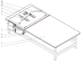
Fig. 1 is an isometric view of a first condition of the present invention for a fluid feed applicator for intensive medical care.
Fig. 2 is an isometric view of a second state of the critical medical care liquid feed applicator of the present invention.
Fig. 3 is an isometric view of a third condition of the fluid feed applicator for intensive medical care of the present invention.
Fig. 4 is an isometric view of a stay and its connecting parts of the fluid feeder for intensive medical care of the present invention.
Fig. 5 is an isometric view of the geneva mechanism and its connecting parts of the fluid feeder for intensive medical care of the invention.
Fig. 6 is an isometric view of a hanging rod and its connecting parts of the liquid feed applicator for intensive medical care of the present invention.
Fig. 7 is an isometric view of the hanger of the fluid feeder for intensive medical care of the invention.
Fig. 8 is an isometric view of the swing link and its connecting parts of the liquid food feeder for intensive medical care of the present invention.
Fig. 9 is an isometric view of a partial rack and its connecting parts of the fluid feeder for intensive medical care of the present invention.
Fig. 10 is a first isometric view of a back-beating bowl and its connecting parts of the fluid feed applicator for intensive medical care of the invention.
Fig. 11 is a second perspective view of a back-beating bowl and its connecting parts of the fluid feeder for intensive medical care of the present invention.
Fig. 12 is an isometric view of the slide plate and its connecting parts of the liquid feed applicator for intensive medical care of the present invention.
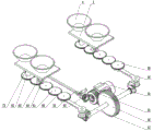
Fig. 13 is an exploded view of a single-forward gear of the liquid diet feeder for intensive care in the medical science according to the present invention.
In the drawings: 1-bedstead, 2-fixed bed board, 3-movable bed board, 4-rising board, 5-sliding board, 6-back knocking bowl, 7-suspension rod, 8-suspension frame, 9-clamping piece, 10-binding band, 11-connecting buckle, 12-supporting rod, 13-supporting disk, 14-worm wheel, 15-worm, 16-first motor, 17-incomplete inner gear ring, 18-incomplete outer gear, 19-bidirectional gear, 20-driving disk, 21-grooved wheel, 22-driving gear, 23-idle gear, 24-telescopic rod, 25-crank rod, 26-pull rod, 27-pull seat, 28-driven gear, 29-rotating shaft, 30-clamping screw, 31-clamping rotating wheel, 32-clamping screw block, 33-clamping rod, 34-clamping slide rod, 35-sealing rod, 36-limiting clamp, 37-swing rod, 38-rising screw block, 39-rising screw rod, 40-accelerating pinion, 41-accelerating bull gear, 42-driving gear, 43-incomplete rack, 44-limiting empty slot, 45-unidirectional left gear, 46-unidirectional right gear, 47-linkage gear, 48-input gear, 49-second gear belt, 50-first gear belt, 51-power gear, 52-telescopic universal joint, 53-guide block, 54-second motor, 55-main gear, 56-unidirectional forward gear, 57-main shaft, 58-crank, 59-fixed gear, 60-connecting rod, 61-moving gear, 62-main cylindrical cam, 63-auxiliary cylindrical cam, 64-reciprocating rod, 65-shunt shaft, 66-external gear ring, 67-internal ratchet, 68-pawl, 69-internal shaft sleeve, 70-synchronous gear, 71-relay gear and 72-follow-up gear.
Detailed Description
The following are specific embodiments of the present invention, and the technical solutions of the present invention will be further described with reference to the drawings, but the present invention is not limited to these embodiments.
As shown in fig. 1-13, the invention provides a liquid food feeding device for nursing in the critical medicine department, comprising a bed frame 1, a fixed bed board 2 is fixedly connected with the rear side of the top of the bed frame 1, a movable bed board 3 capable of swinging back and forth is arranged on the front side of the top of the bed frame 1, a suspension rod 7 capable of swinging back and forth and stretching along with the swinging of the movable bed board 3 is arranged on the front side end of the bed frame 1, a suspension frame 8 capable of swinging back and forth is arranged on the top of the suspension rod 7, and two clamping pieces 9 capable of moving left and right relatively are arranged at the bottom of;
the top of the movable bed plate 3 is provided with a rising plate 4 capable of swinging back and forth, the left side and the right side of the center of the top of the rising plate 4 are respectively provided with a sliding plate 5, the front side and the rear side of the top of the sliding plate 5 are respectively provided with a bowl-shaped back knocking bowl 6, and the back knocking bowl is made of silica gel; the rising plate 4 swings backwards to the limit position to form a structure that the sliding plate 5 reciprocates up and down and the back knocking bowl 6 reciprocates back and forth;
the left side and the right side of the top of the rising plate 4 are respectively provided with a bandage 10, and the tail ends of the bandage 10 are respectively provided with a connecting buckle 11.
The device is provided with the movable bed plate 3 which can swing and the hanging rod 7 which can rotate and extend along with the backward swing of the movable bed plate 3, thereby effectively improving the nursing efficiency of the fluid food feeding of the patient and effectively reducing the occurrence probability of choking; the liquid food bag can be directly placed in the suspension bracket 8, so that the posture inclination adjustment of 15-20 degrees and the lifting of the liquid food bag can be finished in one go.
This device sets up bandage 10 through setting up wobbling board of rising 4 and setting up in the board of rising 4 left and right sides to can chock the patient and adjust to the seat when bucking fast when taking place, reduced medical personnel's nursing work load effectively.
This device is through setting up and starting reciprocating from top to bottom and the back-and-forth reciprocating beat back-and-forth bowl 6 after turning over to the horizontality along with the board of rising 4 to can discharge the liquid food fast, improve the security that the liquid food was fed, guaranteed patient's statement safety effectively.
As shown in fig. 3-4, the rear end of the movable bed plate 3 is hinged to the fixed bed plate 2, the bottom of the bed frame 1 is fixedly connected with a first motor 16, the shaft of the first motor 16 is coaxially and fixedly connected with a worm 15, and the worm 15 is engaged with a worm wheel 14; the worm wheel 14 and the worm 15 are both rotationally connected to the bottom of the bedstead 1; the worm wheel 14 is fixedly connected with a support disc 13, a support rod 12 is hinged to the non-circle center position of the end face of the support disc 13, and the top of the support rod 12 is hinged to the middle of the bottom end of the movable bed plate 3.
The principle of the angle adjustment of the movable bed plate 3 is as follows: when the first motor 16 rotates, the supporting disc 13 rotates through the worm and gear set, so that the supporting disc 13 can drive the supporting rod 12 hinged with the supporting disc to swing, and the relative included angle between the bed plate 3 and the fixed bed plate 2 can be changed (the supporting disc 13, the supporting rod 12 and the movable bed plate 3 form a crank-rocker mechanism).
As shown in fig. 4, the worm wheel 14 is coaxially and fixedly connected with an incomplete inner gear ring 17, and the end surface of the incomplete inner gear ring 17 is coaxially and fixedly connected with an incomplete outer gear 18;
the bottom of the bedstead 1 is rotatably connected with a bidirectional gear 19, and the worm wheel 14 rotates for a circle to form a structure that the incomplete inner gear ring 17 and the incomplete outer gear 18 are respectively meshed with the bidirectional gear 19; the incomplete inner gear ring 17 and the incomplete outer gear 18 are respectively meshed with the bidirectional gear 19 to form a structure that the bidirectional gear 19 rotates positively and negatively.
The number of teeth of the incomplete internal gear ring 17 and the number of teeth of the incomplete external gear 18 are equal to the number of teeth of the bidirectional gear 19, so that the worm wheel 14 rotates one revolution, and the bidirectional gear 19 rotates one revolution in the forward direction and one revolution in the reverse direction.
As shown in fig. 5, a dial 20 is coaxially and fixedly connected to the bidirectional gear 19, the dial 20 is fitted with a grooved pulley 21, the grooved pulley 21 is rotatably connected to the bottom of the bed frame 1, and the dial 20 and the grooved pulley 21 are fitted to form a grooved pulley mechanism;
the grooved pulley 21 is coaxially and fixedly connected with a driving gear 22, the driving gear 22 is meshed with an idler wheel 23, and the idler wheel 23 is rotatably connected to the upper part of the bedstead 1;
the bottom end of the hanging rod 7 is fixedly connected with a rotating shaft 29, and the hanging rod 7 is rotatably connected to the upper part of the bedstead 1 through the rotating shaft 29; the rotating shaft 29 is coaxially and fixedly connected with a driven gear 28, and the driven gear 28 is meshed with the idle gear 23.
When the bidirectional gear 19 rotates for one circle, the driving gear 22 can be driven to rotate for 90 degrees through the geneva gear, so that the driving gear 28 can drive the driven gear 28 and the suspension rod 7 fixedly connected with the driven gear to rotate through the idle gear 23, the supporting disk 13 can rotate for half a circle to rotate the movable bed plate 3 to the maximum angle, and the suspension rod 7 can be positioned in a vertical state; when the supporting disc 13 continues to rotate to one circle, the moving bed plate 3 rotates to the horizontal state and the suspension rod 7 is in the horizontal state again.
As shown in fig. 2, 5 and 6, a sliding hole is formed at the tail end of the suspension rod 7, an expansion rod 24 is connected in the sliding hole in a sliding manner, the top end of the expansion rod 24 is rotatably connected with the suspension frame 8, and a crank rod 25 is fixedly connected to the bottom end of the expansion rod 24;
the front part of the tail end of the turning rod 25 is hinged with a pull rod 26 capable of swinging back and forth, the front end of the pull rod 26 is hinged with a pull seat 27, and the pull seat 27 is fixedly connected with the upper part of the bedstead 1 at the front side of the suspension rod 7.
When the hanging rod 7 is rotated from the horizontal state to the vertical state, the pull rod 26 can be swung, so that the telescopic rod 24 which is slidably connected in the hanging rod 7 can be pushed to slide upwards, and the telescopic rod can be extended while being rotated to the vertical state at the hanging rod 7, so that the liquid food bag fixed on the telescopic rod is lifted to the height, and the liquid food feeding is facilitated.
As shown in fig. 7, a clamping screw 30 is rotatably connected to the top of the suspension bracket 8; the clamping screw 30 is coaxially and fixedly connected with a clamping rotating wheel 31; the clamping screw 30 is in threaded connection with a clamping screw block 32, the left side and the right side of the clamping screw block 32 are respectively hinged with a clamping rod 33, and the tail end of the clamping rod 33 is respectively hinged with the clamping piece 9 at the corresponding position;
the front side and the rear side of the top of the clamping piece 9 are respectively connected with a clamping slide bar 34 in a sliding manner, and the clamping slide bars 34 are fixedly connected to the bottom of the suspension bracket 8;
one end of one of the clamping pieces 9 close to the other clamping piece 9 is fixedly connected with a sealing rod 35, the other clamping piece 9 is provided with a sealing hole, and the sealing rod 35 is connected in the sealing hole in a sliding manner;
the end surfaces of the bottoms of the two clamping pieces 9, which are close to each other, are provided with limiting clamps 36 made of rubber, and the end surfaces of the limiting clamps 36, which are close to each other, are provided with arc grooves.
Through the setting of mounted frame 8, can realize hanging the liquid food bag of belt ring through seal rod 35, can press from both sides the tight location of bottled liquid food bottle through spacing 26 again: the clamping screw 30 is driven to rotate by rotating the clamping rotating wheel 31, so that the clamping screw block 32 can move vertically, the two clamping rods 33 can swing, the two clamping pieces 33 hinged to the clamping rods 33 can relatively approach or relatively separate, and the plugging or the plugging of the sealing rod 35 can be realized 1; 2. the retention clips 36 are moved toward or away from each other. Thereby realizing the positioning of the food container and having higher adaptability.
As shown in fig. 10-12, a second motor 54 is fixedly connected to the center of the bottom of the rising plate 4, a main gear 55 is fixedly connected to the shaft of the second motor 54 coaxially, the main gear 55 is engaged with a single-forward gear 56, the single-forward gear 56 is fixedly connected to a main shaft 57 coaxially, and the main shaft 57 is rotatably connected to the bottom of the rising plate 4;
the left side and the right side of the main shaft 57 are respectively connected with cranks 58 through bevel gear sets, and the cranks 58 are rotationally connected to the bottom of the lifting plate 4; the tail ends of the cranks 58 are respectively hinged with a connecting rod 60, the tail ends of the connecting rods 60 are respectively and rotatably connected with a main cylindrical cam 62, the bottom end of the main cylindrical cam 62 is coaxially and fixedly connected with a follow-up gear 72, and the top end of the main cylindrical cam 62 is rotatably connected with the sliding plate 5; the sliding plates 5 are respectively connected to the left side and the right side of the center of the rising plate 4 in a sliding manner;
the tail end of the crank 58 is fixedly connected with a fixed gear 59, and the axis of a hinge shaft of the crank 58 and the connecting rod 60 is coaxial with the axis of the fixed gear 59; the top of the connecting rod 60 is rotatably connected with a plurality of mutually meshed moving gears 61 along the length direction, and the two moving gears 61 at the two ends are respectively meshed with the fixed gear 59 and the driven gear 72;
the center of the bottom of the sliding plate 5 is rotatably connected with a relay gear 71; the rear side of the bottom of the sliding plate 5 is rotatably connected with a slave cylindrical cam 63; the top ends of the main cylindrical cam 62 and the auxiliary cylindrical cam 63 are respectively coaxially and fixedly connected with a synchronizing gear 70, and the synchronizing gears 70 are all meshed with a relay gear 71;
the peripheries of the main cylindrical cam 62 and the auxiliary cylindrical cam 63 are provided with wavy closed guide grooves; the bottom end of the back knocking bowl 6 is fixedly connected with a reciprocating rod 64, the reciprocating rod 64 is connected with the sliding plate 5 in a sliding mode, the side face of the bottom end of the reciprocating rod 64 is fixedly connected with guide pillars respectively, and the guide pillars are connected in closed guide grooves in corresponding positions in a sliding mode respectively.
When the second motor 54 rotates in the forward direction, the main gear 55 rotates with the single-direction gear 56, so that the main shaft 57 can rotate, the two cranks 59 can rotate through the bevel gear set (the cranks 59, the connecting rods 60 and the sliding plates 5 form a crank-slider mechanism), the two sliding plates 5 can be driven by the connecting rods 60 to move in a reciprocating manner, and the two back beating bowls 6 can be driven to move in a reciprocating manner along the back of the patient.
When the crank slider mechanism works, the crank 59 rotates to drive the plurality of movable gears 61 to rotate through the fixed gear 59 fixedly connected with the crank 59, so that the main cylindrical cam 62 can rotate, and the main cylindrical cam 62 can drive the slave cylindrical cam 63 to rotate through the synchronous gear 70 and the relay gear 71; thereby can drive the guide pillar and the reciprocating lever 64 fixedly connected with the guide pillar to rotate through the closed guide groove, thereby realizing the back-and-forth reciprocating motion of the back knocking bowl 6 and realizing the back knocking operation.
When the second motor 54 rotates reversely, the slider-crank mechanism is not operated due to the presence of the single forward gear 56, i.e., the back-knocking operation is not performed
As shown in fig. 8-9, the shaft of the second motor 54 is connected with a diversion shaft 65 through a bevel gear assembly, and the diversion shaft 65 is rotatably connected with the bottom of the rising plate 4; the shunt shaft 65 is connected with a power gear 51 through a telescopic universal joint 52, and the power gear 51 is rotationally connected to the bottom of the movable bed plate 3; the telescopic gimbal 52 is prior art and will not be described in any greater detail.
The power gear 51 is connected with an input gear 48 through a first gear belt 50, the input gear 48 is connected with a linkage gear 47 through a second gear belt 49, and the input gear 48 and the linkage gear 47 are both rotationally connected to the bottom of the movable bed plate 3; the input gear 48 is coaxially and fixedly connected with a single right gear 46, the linkage gear 47 is coaxially and fixedly connected with a one-way left gear 45, and the one-way left gear 45 and the one-way right gear 46 are meshed and connected with an incomplete rack 43; the top of the incomplete rack 43 is slidably connected with a guide block 53, and the guide block 53 is fixedly connected to the bottom of the movable bed plate 3;
the incomplete rack 43 is meshed and connected with a driving gear 42, the driving gear 42 is coaxially and fixedly connected with an accelerating large gear 41, the accelerating large gear 41 is rotatably connected to the bottom of the movable bed plate 3, the accelerating large gear 41 is meshed and connected with an accelerating small gear 40, the accelerating small gear 40 is coaxially and fixedly connected with a rising screw 39, and the rising screw 39 is rotatably connected to the bottom of the movable bed plate 3; the rising screw 39 is in threaded connection with a rising screw block 38, the rising screw block 38 is hinged with a swing rod 37, and the top of the swing rod 37 is hinged with the bottom of the rising plate 4; the back end of the rising plate 4 is hinged with the movable bed plate 3. The middle part and two ends of the incomplete rack 43 are respectively provided with a limit empty groove 44; the structures of the single forward gear 56, the unidirectional left gear 45 and the unidirectional right gear 46 are the same; the structure of the unidirectional left gear 45 and the unidirectional right gear 46 is bilaterally symmetrical.
When the second motor 54 rotates forward, the main gear 55 can drive the diversion shaft 65 and the telescopic universal joint 52 to rotate, and further drive the power gear 51 to rotate, the power gear 51 drives the input gear 48 to rotate forward, the input gear 48 drives the linkage gear 47 to rotate forward, so that the single-right gear 46 can rotate (at the moment, the single-direction left gear 45 idles and does not transmit power), the single-right gear 46 can drive the incomplete rack 43 to move, so that the driving gear 42 can rotate, after the accelerated transmission from the accelerating large gear 41 to the accelerating small gear 40, the rising screw 39 can accelerate to rotate forward, so that the rising screw block 38 in threaded connection with the rising screw block can move along the axial direction of the rising screw 39, so that the swing rod 37 can swing, so that the rising plate 4 can swing, and the rising operation of a patient can be realized. And when the rising board 4 swings to the limit position, the single right gear 46 is not meshed with the incomplete rack 43 due to the existence of the limit empty groove 44, so that the rising board 4 can be positioned at the current position.
When the second motor 54 rotates reversely, the power gear 51 drives the input gear 48 to rotate reversely, the input gear 48 drives the linkage gear 47 to rotate reversely, the one-way left gear 45 rotates and can drive the incomplete rack 43 to move (at the moment, the one-way right gear 46 idles and does not transmit power), so that the incomplete rack 43 drives the driving gear 42 to rotate, after the acceleration transmission from the acceleration large gear 41 to the acceleration small gear 40, the rising screw 39 is accelerated to rotate reversely, the rising screw block 38 in threaded connection with the rising screw block can move along the axial direction of the rising screw 39, the swing rod 37 can swing, the rising plate 4 can swing, and a patient can lie on the movable bed plate 3 at an angle of 15-20 degrees again.
As shown in fig. 12 to 13, the single forward gear 56, the one-way left gear 45 and the one-way right gear 46 each include an outer ring gear 66, and an inner circumference of the outer ring gear 66 is provided with an inner ratchet 67; an inner sleeve 69 is rotatably connected to the inner circumference of the outer ring gear 66, a plurality of pawls 68 are rotatably connected to the outer circumference of the inner sleeve 69, and the pawls 68 are engaged with the inner ratchet 67. Torsion springs are provided on the hinge axes of the pawls 68 and the inner bushing 69.
The inner shaft sleeves 69 of the single-direction forward gear 56, the one-direction left gear 45 and the one-direction right gear 46 are respectively and fixedly connected with corresponding shafts, and when the shafts fixedly connected with the single-direction forward gear, the outer gear ring 66 can be driven to rotate by the pawl 68, so that power transmission can be realized; when the shaft fixedly connected with the pawl 68 rotates reversely, the pawl 68 does not drive the inner ratchet 67 and the outer gear ring 66, and only can idle, and power transmission cannot be realized.
When the device is used and liquid food feeding is needed, a liquid food container is placed in the suspension bracket 8 and positioned, a patient is positioned through the binding band 10 and the connecting buckle 11, the first motor 16 is controlled to work, an included angle of 15-20 degrees is formed between the movable bed plate 3 and the fixed bed plate 2, and the suspension rod 7 extends and swings to a vertical state; carry out the liquid food and feed, when appearing chocking and coughing the state, control second motor 54 work for rise body plate 3 and swing to being close vertical state, and beat back bowl 6 and can realize reciprocating from top to bottom and reciprocating motion all around, thereby can realize the patting to patient's back, will chock through beating the back and coughing the thing and discharge, reduced medical personnel's work load effectively, improved the security that the liquid food was fed.
The specific embodiments described herein are merely illustrative of the spirit of the invention. Various modifications or additions may be made to the described embodiments or alternatives may be employed by those skilled in the art without departing from the spirit or ambit of the invention as defined in the appended claims.
Although the bed frame 1, the fixed bed plate 2, the moving bed plate 3, the rising plate 4, the sliding plate 5, the back-beating bowl 6, the suspension rod 7, the suspension bracket 8, the clamping piece 9, the binding band 10, the connecting buckle 11, the stay bar 12, the stay disc 13, the worm wheel 14, the worm 15, the first motor 16, the incomplete internal gear ring 17, the incomplete external gear 18, the two-way gear 19, the dial 20, the grooved wheel 21, the driving gear 22, the idle gear 23, the telescopic rod 24, the crank 25, the pull rod 26, the pull seat 27, the driven gear 28, the rotating shaft 29, the clamping screw 30, the clamping rotating wheel 31, the clamping screw block 32, the clamping rod 33, the clamping sliding rod 34, the sealing rod 35, the limit clamp 36, the swinging rod 37, the rising screw block 38, the rising screw 39, the accelerating pinion 40, the accelerating large gear 41, the driving gear 42, the incomplete rack 43, the limit empty slot 44, the one-way left gear 45, the one-way, The terms of the input gear 48, the second gear belt 49, the first gear belt 50, the power gear 51, the telescopic universal joint 52, the guide block 53, the second motor 54, the main gear 55, the one-way front gear 56, the main shaft 57, the crank 58, the fixed gear 59, the connecting rod 60, the moving gear 61, the main cylindrical cam 62, the slave cylindrical cam 63, the reciprocating rod 64, the shunt shaft 65, the outer gear ring 66, the inner ratchet 67, the pawl 68, the inner bushing 69, the synchronizing gear 70, the relay gear 71 and the follower gear 72 are used, but the possibility of using other terms is not excluded. These terms are used merely to more conveniently describe and explain the nature of the present invention; they are to be construed as being without limitation to any additional limitations that may be imposed by the spirit of the present invention.
Claims (9)
1. The utility model provides a liquid food feeding device of severe medical science nursing usefulness, includes bedstead (1), and bedstead (1) top rear side fixedly connected with decides bed board (2), but bedstead (1) top front side is provided with swing back and forth moves bed board (3), its characterized in that: a suspension rod (7) which can swing back and forth and stretch along with the swing of the movable bed plate (3) is arranged at the front side end of the bed frame (1), a suspension frame (8) which can swing back and forth is arranged at the top of the suspension rod (7), and two clamping pieces (9) which can move left and right relatively are arranged at the bottom of the suspension frame (8);
the top of the movable bed plate (3) is provided with a lifting plate (4) capable of swinging back and forth, the left side and the right side of the center of the top of the lifting plate (4) are respectively provided with a sliding plate (5), and the front side and the rear side of the top of the sliding plate (5) are respectively provided with a bowl-shaped back knocking bowl (6); the lifting plate (4) swings backwards to a limit position to form a structure that the sliding plate (5) reciprocates up and down and the back knocking bowl (6) reciprocates back and forth;
the left side and the right side of the top of the rising plate (4) are respectively provided with a binding belt (10), and the tail ends of the binding belts (10) are respectively provided with a connecting buckle (11).
2. The liquid diet feeder for intensive medical care of claim 1, characterized in that: the rear end of the movable bed plate (3) is hinged with the fixed bed plate (2), the bottom of the bed frame (1) is fixedly connected with a first motor (16), the shaft of the first motor (16) is coaxially and fixedly connected with a worm (15), and the worm (15) is meshed with a worm wheel (14); the worm wheel (14) and the worm (15) are both rotationally connected to the bottom of the bedstead (1); the worm wheel (14) is fixedly connected with a support disc (13), a support rod (12) is hinged to the non-circle center position of the end face of the support disc (13), and the top of the support rod (12) is hinged to the middle of the bottom end of the movable bed plate (3).
3. The liquid diet feeder for intensive medical care as set forth in claim 2, wherein: the worm wheel (14) is coaxially and fixedly connected with an incomplete inner gear ring (17), and the end face of the incomplete inner gear ring (17) is coaxially and fixedly connected with an incomplete outer gear (18);
the bottom of the bedstead (1) is rotatably connected with a bidirectional gear (19), and the worm wheel (14) rotates for a circle to form a structure that the incomplete inner gear ring (17) and the incomplete outer gear (18) are respectively meshed with the bidirectional gear (19); the incomplete inner gear ring (17) and the incomplete outer gear (18) are respectively meshed with the bidirectional gear (19) to form a structure that the bidirectional gear (19) rotates positively and negatively.
4. The liquid diet feeder for intensive medical care as set forth in claim 3, wherein: the bidirectional gear (19) is coaxially and fixedly connected with a driving plate (20), the driving plate (20) is matched with a grooved wheel (21), the grooved wheel (21) is rotatably connected to the bottom of the bedstead (1), and the driving plate (20) and the grooved wheel (21) are matched to form a grooved wheel mechanism;
the grooved pulley (21) is coaxially and fixedly connected with a driving gear (22), the driving gear (22) is meshed with an idler (23), and the idler (23) is rotatably connected to the upper part of the bedstead (1);
the bottom end of the suspension rod (7) is fixedly connected with a rotating shaft (29), and the suspension rod (7) is rotatably connected to the upper part of the bedstead (1) through the rotating shaft (29); the rotating shaft (29) is coaxially and fixedly connected with a driven gear (28), and the driven gear (28) is meshed with the idle gear (23).
5. The liquid diet feeder for intensive medical care of claim 1, characterized in that: the tail end of the suspension rod (7) is provided with a sliding hole, a telescopic rod (24) is connected in the sliding hole in a sliding mode, the top end of the telescopic rod (24) is rotatably connected with the suspension frame (8), and the bottom end of the telescopic rod (24) is fixedly connected with a turning rod (25);
the front part of the tail end of the turning rod (25) is hinged with a pull rod (26) capable of swinging back and forth, the front end of the pull rod (26) is hinged with a pull seat (27), and the pull seat (27) is fixedly connected to the upper part of the bedstead (1) at the front side of the suspension rod (7).
6. The liquid diet feeder for intensive medical care of claim 1, characterized in that: the top of the suspension bracket (8) is rotationally connected with a clamping screw (30); the clamping screw (30) is coaxially and fixedly connected with a clamping rotating wheel (31); the clamping screw rod (30) is in threaded connection with a clamping screw block (32), the left side and the right side of the clamping screw block (32) are respectively hinged with a clamping rod (33), and the tail end of the clamping rod (33) is respectively hinged with a clamping piece (9) at a corresponding position;
the front side and the rear side of the top of the clamping piece (9) are respectively connected with a clamping slide rod (34) in a sliding manner, and the clamping slide rods (34) are fixedly connected to the bottom of the suspension frame (8);
one end of one clamping piece (9) close to the other clamping piece (9) is fixedly connected with a sealing rod (35), the other clamping piece (9) is provided with a sealing hole, and the sealing rod (35) is connected in the sealing hole in a sliding manner;
the end faces, close to each other, of the bottoms of the two clamping pieces (9) are provided with limiting clamps (36) made of rubber, and arc grooves are formed in the end faces, close to each other, of the limiting clamps (36).
7. The liquid diet feeder for intensive medical care of claim 1, characterized in that: the center of the bottom of the lifting plate (4) is fixedly connected with a second motor (54), a main gear (55) is coaxially and fixedly connected with the shaft of the second motor (54), the main gear (55) is meshed with a single-forward gear (56), the single-forward gear (56) is coaxially and fixedly connected with a main shaft (57), and the main shaft (57) is rotatably connected to the bottom of the lifting plate (4);
the left side and the right side of the main shaft (57) are respectively connected with cranks (58) through bevel gear sets, and the cranks (58) are rotationally connected to the bottom of the lifting plate (4); the tail ends of the cranks (58) are respectively hinged with a connecting rod (60), the tail ends of the connecting rods (60) are respectively and rotatably connected with a main cylindrical cam (62), the bottom end of the main cylindrical cam (62) is coaxially and fixedly connected with a follow-up gear (72), and the top end of the main cylindrical cam (62) is rotatably connected with the sliding plate (5); the sliding plates (5) are respectively connected to the left side and the right side of the center of the lifting plate (4) in a sliding manner;
the tail end of the crank (58) is fixedly connected with a fixed gear (59), and the axis of a hinged shaft of the crank (58) and the connecting rod (60) is coaxial with the axis of the fixed gear (59); the top of the connecting rod (60) is rotatably connected with a plurality of mutually meshed moving gears (61) along the length direction, and the two moving gears (61) at the two ends are respectively meshed with the fixed gear (59) and the follow-up gear (72);
the center of the bottom of the sliding plate (5) is rotatably connected with a relay gear (71); the rear side of the bottom of the sliding plate (5) is rotatably connected with a slave cylindrical cam (63); the top ends of the main cylindrical cam (62) and the auxiliary cylindrical cam (63) are respectively coaxially and fixedly connected with a synchronous gear (70), and the synchronous gears (70) are all meshed with the relay gear (71);
the peripheries of the main cylindrical cam (62) and the auxiliary cylindrical cam (63) are provided with wavy closed guide grooves; percussion back bowl (6) bottom equal fixedly connected with reciprocating lever (64), reciprocating lever (64) all with slide (5) sliding connection, reciprocating lever (64) bottom side fixedly connected with guide pillar respectively, guide pillar sliding connection respectively in the closed guide slot that corresponds the position.
8. The liquid diet feeder for intensive medical care as set forth in claim 7, wherein: a shaft of the second motor (54) is connected with a shunt shaft (65) through a bevel gear set, and the shunt shaft (65) is rotationally connected to the bottom of the lifting plate (4); the shunt shaft (65) is connected with a power gear (51) through a telescopic universal joint (52), and the power gear (51) is rotationally connected to the bottom of the movable bed plate (3);
the power gear (51) is connected with an input gear (48) through a first gear belt (50), the input gear (48) is connected with a linkage gear (47) through a second gear belt (49), and the input gear (48) and the linkage gear (47) are both rotationally connected to the bottom of the movable bed plate (3); the input gear (48) is coaxially and fixedly connected with a single right gear (46), the linkage gear (47) is coaxially and fixedly connected with a one-way left gear (45), and the one-way left gear (45) and the one-way right gear (46) are meshed and connected with an incomplete rack (43); the top of the incomplete rack (43) is connected with a guide block (53) in a sliding way, and the guide block (53) is fixedly connected to the bottom of the movable bed plate (3);
the incomplete rack (43) is meshed and connected with a driving gear (42), the driving gear (42) is coaxially and fixedly connected with an accelerating large gear (41), the accelerating large gear (41) is rotatably connected to the bottom of the movable bed plate (3), the accelerating large gear (41) is meshed and connected with an accelerating small gear (40), the accelerating small gear (40) is coaxially and fixedly connected with a rising screw (39), and the rising screw (39) is rotatably connected to the bottom of the movable bed plate (3); the rising screw (39) is in threaded connection with a rising screw block (38), the rising screw block (38) is hinged with a swing rod (37), and the top of the swing rod (37) is hinged with the bottom of the rising plate (4); the rear end of the rising plate (4) is hinged with the movable bed plate (3).
9. The liquid diet feeder for intensive medical care of claim 8, wherein: the middle part and two ends of the incomplete rack (43) are respectively provided with a limit empty groove (44); the structures of the single forward gear (56), the one-way left gear (45) and the one-way right gear (46) are the same; the structure of the unidirectional left gear (45) and the unidirectional right gear (46) is bilaterally symmetrical;
the single forward gear (56), the unidirectional left gear (45) and the unidirectional right gear (46) respectively comprise an outer gear ring (66), and inner ratchets (67) are arranged on the inner circumference of the outer gear ring (66); an inner shaft sleeve (69) is rotatably connected to the inner circumference of the outer gear ring (66), a plurality of pawls (68) are rotatably connected to the outer circumference of the inner shaft sleeve (69), and the pawls (68) are meshed with the inner ratchet (67).
Priority Applications (1)
| Application Number | Priority Date | Filing Date | Title |
|---|---|---|---|
| CN202010942336.5A CN111870449A (en) | 2020-09-09 | 2020-09-09 | Liquid food feeding device for nursing in critical medicine department |
Applications Claiming Priority (1)
| Application Number | Priority Date | Filing Date | Title |
|---|---|---|---|
| CN202010942336.5A CN111870449A (en) | 2020-09-09 | 2020-09-09 | Liquid food feeding device for nursing in critical medicine department |
Publications (1)
| Publication Number | Publication Date |
|---|---|
| CN111870449A true CN111870449A (en) | 2020-11-03 |
Family
ID=73199410
Family Applications (1)
| Application Number | Title | Priority Date | Filing Date |
|---|---|---|---|
| CN202010942336.5A Withdrawn CN111870449A (en) | 2020-09-09 | 2020-09-09 | Liquid food feeding device for nursing in critical medicine department |
Country Status (1)
| Country | Link |
|---|---|
| CN (1) | CN111870449A (en) |
Cited By (3)
| Publication number | Priority date | Publication date | Assignee | Title |
|---|---|---|---|---|
| CN112690969A (en) * | 2020-12-28 | 2021-04-23 | 南阳医学高等专科学校第一附属医院 | Heart failure patient nursing device |
| CN113876509A (en) * | 2021-08-31 | 2022-01-04 | 易紫辉 | ICU intensive care therapy is with multi-purpose nursing bed of intelligence |
| CN115350014A (en) * | 2022-09-17 | 2022-11-18 | 青岛大学附属医院 | But one-man operation's severe nursing patient stands up equipment |
-
2020
- 2020-09-09 CN CN202010942336.5A patent/CN111870449A/en not_active Withdrawn
Cited By (6)
| Publication number | Priority date | Publication date | Assignee | Title |
|---|---|---|---|---|
| CN112690969A (en) * | 2020-12-28 | 2021-04-23 | 南阳医学高等专科学校第一附属医院 | Heart failure patient nursing device |
| CN112690969B (en) * | 2020-12-28 | 2022-03-15 | 南阳医学高等专科学校第一附属医院 | Heart failure patient nursing device |
| CN113876509A (en) * | 2021-08-31 | 2022-01-04 | 易紫辉 | ICU intensive care therapy is with multi-purpose nursing bed of intelligence |
| CN113876509B (en) * | 2021-08-31 | 2022-11-15 | 广西医科大学第一附属医院 | ICU intensive care therapy is with multi-purpose nursing bed of intelligence |
| CN115350014A (en) * | 2022-09-17 | 2022-11-18 | 青岛大学附属医院 | But one-man operation's severe nursing patient stands up equipment |
| CN115350014B (en) * | 2022-09-17 | 2024-04-12 | 青岛大学附属医院 | Single-person-operated equipment for turning over patients in intensive care |
Similar Documents
| Publication | Publication Date | Title |
|---|---|---|
| CN111870449A (en) | Liquid food feeding device for nursing in critical medicine department | |
| CN110975109A (en) | Clinical interventional therapy pipe fixing device of medical oncology | |
| CN107625593B (en) | Sickbed with patient capable of being obliquely shifted | |
| CN113350140B (en) | Clinical antipruritic device of using of dermatology | |
| CN110464407A (en) | A kind of Cardiological clinic compression hemostasis device | |
| CN114027899A (en) | Multifunctional retractor for clinical operation of general surgery department | |
| CN112754780B (en) | Multifunctional rescue device for emergency department | |
| CN112006883A (en) | Gynecological drug delivery device | |
| CN217286554U (en) | Stomach tube with anticreep function | |
| CN216317997U (en) | Medical instrument placing bracket for obstetrics and gynecology department | |
| CN112426297B (en) | Uterus postoperative care device | |
| CN214017881U (en) | Dressing auxiliary frame for operating room nursing | |
| CN110464604B (en) | Automatic limb rehabilitation machine | |
| CN113576839A (en) | Cardiothoracic surgery is with nursing auxiliary device | |
| CN218075510U (en) | Horizontal upper limb rehabilitation device | |
| CN213642506U (en) | Gastric lavage device for gastroenterology department | |
| CN109663166A (en) | A kind of transfusion nursing device | |
| CN220089860U (en) | Surgical pulling shoulder strap for preventing pressure sores | |
| CN213554424U (en) | Infusion nursing device for neurology | |
| CN220833772U (en) | Auxiliary positioner for transfusion port | |
| CN112690884B (en) | Progenesis branch of academic or vocational study pierces and gets special protector of ovum | |
| CN219439440U (en) | Nursing tray for high-energy radiation therapy for PETCT nursing | |
| CN209004579U (en) | A kind of medical Chinese medicine Cardiological diagnostic equipment | |
| CN219375769U (en) | Foldable threaded pipe bracket for anesthesia department | |
| CN106823046A (en) | Patient is avoided to lift the wearing mechanism of infusion bottle |
Legal Events
| Date | Code | Title | Description |
|---|---|---|---|
| PB01 | Publication | ||
| PB01 | Publication | ||
| SE01 | Entry into force of request for substantive examination | ||
| SE01 | Entry into force of request for substantive examination | ||
| WW01 | Invention patent application withdrawn after publication | ||
| WW01 | Invention patent application withdrawn after publication |
Application publication date: 20201103 |