CN112649191A - Worm tooth groove width comparison detection device and method - Google Patents
Worm tooth groove width comparison detection device and method Download PDFInfo
- Publication number
- CN112649191A CN112649191A CN202011378427.7A CN202011378427A CN112649191A CN 112649191 A CN112649191 A CN 112649191A CN 202011378427 A CN202011378427 A CN 202011378427A CN 112649191 A CN112649191 A CN 112649191A
- Authority
- CN
- China
- Prior art keywords
- worm
- dial indicator
- tooth
- frame
- ball head
- Prior art date
- Legal status (The legal status is an assumption and is not a legal conclusion. Google has not performed a legal analysis and makes no representation as to the accuracy of the status listed.)
- Granted
Links
Images


Classifications
-
- G—PHYSICS
- G01—MEASURING; TESTING
- G01M—TESTING STATIC OR DYNAMIC BALANCE OF MACHINES OR STRUCTURES; TESTING OF STRUCTURES OR APPARATUS, NOT OTHERWISE PROVIDED FOR
- G01M13/00—Testing of machine parts
- G01M13/02—Gearings; Transmission mechanisms
Abstract
The invention discloses a device and a method for detecting width contrast of a worm tooth groove. The device comprises a mobile control module, a tested piece clamping module, a detection module and a supporting and fixing module. The measuring seat of the Z-direction upright post movement control module is arranged on the upright post through a lifting nut and can be lifted in the Z-axis direction; and a dial indicator with a metal measuring ball head is arranged on the measuring seat. The worm is fixed by installing the left thimble frame and the right thimble frame on the X-direction moving guide rail, and the metal measuring ball head in the Z direction can be arranged between two teeth of the worm after moving and adjusting. After the dial indicator is zeroed by the standard worm, the width of each tooth groove of the worm to be detected is contrasted and detected, and if the reading of the dial indicator is zero, no deviation exists; otherwise, the tooth groove width of the worm to be measured and the standard worm has deviation. The invention can rapidly carry out contrast detection on the width of the worm tooth groove through reading of the dial indicator, and has the advantages of small motion error, high measurement precision and wide application range.
Description
Technical Field
The invention relates to a device suitable for worm tooth groove width comparison detection, in particular to a device and a method capable of realizing comparison detection of worm tooth groove widths with different moduli.
Background
The worm transmission consists of a worm wheel and a worm, wherein the worm is a driving part; in the transmission process, the efficiency is low, the sliding speed is high, and the heat is easy to generate, so that the worm machining usually needs higher precision, and particularly, the detection of the width of the tooth groove of the worm is a main means for controlling the machining size of the tooth part of the worm.
At present, in the machining process of mechanical production, workers need to detect finished worms after machining and production so as to ensure the qualified rate of products. The method is characterized in that a direct measurement method is generally adopted for detecting the width of the tooth groove of the worm, namely, the tooth groove width is manually measured by holding a ruler one tooth by a caliper, and the deviation of the tooth groove width measured by the caliper is based on the addendum circle.
Therefore, it is very important to develop a device capable of rapidly and reliably checking the tooth space width of the worm. The device needs to quickly reflect whether the deviation exists between the tooth groove width of the worm to be detected and the tooth groove width of the standard worm, and improves and perfects the product quality detection capability and quality tracing management system of enterprises.
Disclosure of Invention
In view of the shortcomings in the prior art in the background art, the present invention aims to provide a device and a method for detecting the width contrast of a worm tooth groove.
The technical scheme adopted by the invention for solving the technical problems is as follows:
the detection device comprises a mobile control module, a to-be-detected piece clamping module, a detection module and a supporting and fixing module; the movement control module comprises an X-direction guide rail movement control module and a Z-direction upright post movement control module;
the X-direction guide rail movement control module comprises a measurement experiment pedestal, a left thimble frame and a right thimble frame, wherein the measurement experiment pedestal comprises a movable guide rail, a bakelite hand wheel and a bakelite nut;
the X-direction guide rail movement control module is mainly used for controlling the left thimble frame and the right thimble frame to move along the X direction, and adjusting a bakelite nut of the thimble frame to roughly adjust the position of the worm in the X direction so that a metal measuring ball head in the Z direction can be between two teeth of the worm; a thimble frame handle on the right thimble frame is used for controlling the right thimble to move left and right to load and unload the worm;
the bakelite handwheel is used for fine adjustment of the position of the movable guide rail;
the clamping module of the tested part is arranged on the left thimble frame and the right thimble frame, comprises a left thimble and a right thimble and is mainly used for fixing the worm in the X direction;
the Z-direction upright post movement control module comprises a measuring seat, a lifting nut and an upright post; the measuring seat is arranged on the upright post through a lifting nut, and the lifting of the measuring seat in the Z-axis direction can be realized by adjusting the lifting nut;
the detection module comprises a dial indicator, a metal measuring ball head, a metal connecting rod and an indicator frame, the indicator frame is arranged on the measuring seat and can be lifted up or put down by using an indicator frame handle, and the dial indicator is arranged on the indicator frame through a threaded through hole;
and worms with different tooth space widths are provided with metal measuring bulbs with different measuring diameters, the metal measuring bulbs are positioned at the tail ends of metal connecting rods, and the other ends of the metal connecting rods are connected with the dial indicator by virtue of threads.
The supporting and fixing module comprises a bakelite screw, a fastening screw, a common screw, an M4 bakelite screw, a spring, a supporting stop block, a metal baffle plate and a metal connecting block.
The device adopts the dial indicator to detect the tooth groove width of the worm to be detected and judges whether the tooth groove width of the worm to be detected has deviation with the tooth groove width of the standard worm. The worm that the device can measure measures the modulus and is 1 ~ 6mm, measures the maximum diameter and is 300 mm.
The X-direction guide rail movement control module can be provided with worms with different modules, and can adjust the position of the worm relative to the metal measuring ball head, so that the dial indicator can inspect the width of the tooth slot of each tooth of the worm.
The Z-direction upright post movement control module can control the measuring seat to move up and down along the Z axis, the dial indicator on the gauge stand can be put down by lifting the gauge stand handle, and the metal measuring ball head under the dial indicator is customized according to the worms with different tooth socket widths so as to detect the tooth socket width of the corresponding worm. And adjusting the positions of the metal measuring ball head and the worm to enable the metal measuring ball head at the lower end of the dial indicator to be positioned at the position where the tooth space of the worm is close to the reference circle of the gear, and reading the reading of the dial indicator to finish the rapid comparison and detection of the width of the tooth space of the worm to be detected relative to the standard worm.
The method for realizing the comparative detection of the width of the worm tooth groove by using the device comprises the following steps: firstly, completing zero setting work before detecting the width of a tooth socket of a worm to be detected;
installing a standard worm between a left thimble frame and a right thimble frame, roughly adjusting the position of the standard worm relative to a metal measuring ball head to enable one tooth groove of the standard worm to be roughly positioned below the metal measuring ball head, clamping the standard worm by a left thimble and a right thimble, adjusting a lifting nut on a stand column to control the Z-direction height of a measuring seat, lifting a handle of the gauge frame, putting down a dial indicator to enable the metal measuring ball head to be in contact with the standard worm after the dial indicator is put down, finding a certain position of the metal measuring ball head on the standard worm to enable the reading of the dial indicator to be minimum, namely roughly positioning the center of the ball of the metal measuring ball head at a reference circle of two teeth of the standard worm, and adjusting the reading of the dial indicator to enable the reading;
secondly, mounting a worm to be tested;
putting down a meter frame handle, lifting up a dial indicator, releasing a thimble frame handle on a right thimble frame, detaching a standard worm, locking the thimble frame handle, mounting a worm to be measured on a left thimble and a right thimble, roughly adjusting the position of the worm to be measured relative to a metal measuring ball head, enabling a first tooth socket of the worm to be measured to be roughly positioned below the metal measuring ball head, locking the thimble frame handle of the right thimble frame, lifting up the meter frame handle, putting down the dial indicator, enabling the metal measuring ball head to be positioned between a first tooth and a second tooth, and adjusting a bakelite hand wheel to finish fine adjustment;
thirdly, comparing and detecting the width of the tooth groove;
observing the reading of the dial indicator, judging whether the reading is located at a zero position, if so, putting down the handle, lifting up the dial indicator, adjusting the position of the worm to be measured according to the second step mode to enable the second tooth socket of the worm to be measured to be approximately located below the metal measuring ball head, lifting up the handle, putting down the dial indicator to enable the measuring ball head to be located between the second tooth and the third tooth, finely adjusting a bakelite hand wheel, and similarly observing whether the reading of the dial indicator is located at the zero position, so that whether the second tooth socket width of the worm to be measured and the standard worm have deviation can be judged; the width of the other residual tooth grooves is measured in the same way, so that the width of each tooth groove of the worm to be detected is quickly detected; if the reading of the dial indicator is not at the zero position, the tooth groove width of the worm to be measured and the tooth groove width of the standard worm have deviation.
In the detection method, when the standard worm is adjusted to zero, the metal measuring ball head enables the position where the reading of the dial indicator is the smallest to be located at the reference circle position of the worm, namely the sphere center of the metal measuring ball head is located at the reference circle position. For a standard worm, the pitch diameter d (radius r) and the root diameter df(radius r)f) And a determined relation exists, the distance from the sphere center of the measuring ball head to the root circle is set to be delta d, the delta d is equal to 1.25m, wherein m is the modulus of the worm, z is the tooth number, for the same standard worm, the delta d and the tooth groove width e meet a certain geometrical relation, and if the proportionality coefficient is k, different k values exist for standard worms with different moduli. When the worm to be measured is measured, if delta d changes, namely the width of the tooth groove of the worm to be measured is deviated from that of the standard worm, and the reading of the dial indicator is not in a zero position. Wherein:
d=mz (1)
df=m(z-2.5) (2)

Δd=ke (4)
when the width of the tooth groove of the worm to be measured is detected, if the reading of the dial indicator deviates to the left or to the right, the width e 'of the tooth groove of the worm to be measured is larger than or smaller than the width e of the tooth groove of the standard worm, at the moment, the distance delta d' from the center of the metal measuring ball head to the tooth root circle of the worm to be measured is smaller than or larger than the distance delta d from the center of the metal measuring ball head to the tooth root circle of the standard worm, the reading of the dial indicator is marked as l, the difference delta between the delta d and the delta d 'is the reading l of the dial indicator, and the difference delta between the delta d and the delta d' and the change delta e of the tooth groove width are in the relationship that the proportionality coefficient is k:
l=Δd′-Δd=δ=k′(e′-e)=k′Δe (5)
compared with the background art, the invention has the beneficial effects that:
1. according to the invention, the dial indicator and the metal measuring ball head are connected through the metal connecting rod, so that the tooth groove widths of the standard worm and the worm to be measured with the same modulus can be rapidly compared and detected, and the reading of the dial indicator is the deviation value corresponding to the tooth groove width;
2. the invention adopts the metal measuring ball heads with the corresponding diameters to detect the standard worms and the to-be-measured worms with different moduli, and the metal measuring ball heads are customized by turning according to the tooth space widths of the worms with different moduli, so that the invention can adapt to the to-be-measured worms with different tooth space widths, can obviously improve the measuring accuracy, has wider practical application and can more accurately reflect the actual condition of the tooth space width of the to-be-measured worm;
3. the worm modulus range capable of being detected by the device is 1-6 mm, the maximum diameter of detection is 300mm, the highest precision of perpendicularity is 0.005-0.003, and the highest precision of parallelism is 0.008-0.01, and the device is small in motion error, high in stability precision, good in mechanical contact and compact in structural design;
4. the horizontal position of the left thimble frame and the right thimble frame on the X-direction guide rail is changed to fixedly install the worms with different moduli, so that the application is more convenient and quicker;
5. the lifting of the dial indicator and the metal measuring ball head can be realized through the Z-direction upright post movement control module, the operation is convenient, and the detection efficiency is high.
Drawings
Fig. 1 is a general configuration diagram of a worm tooth width contrast detecting device of the present invention.
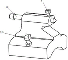
FIG. 2 is a schematic view of the structure of the measurement experiment bench of the present invention.
Fig. 3 is a schematic structural view of the left thimble frame of the present invention.
Fig. 4 is a schematic structural view of the right thimble frame of the present invention.
Fig. 5 is a schematic structural diagram of the metal measuring ball head of the present invention.
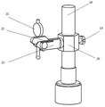
FIG. 6 is a schematic view of the Z-pillar movement control module of the present invention.
Fig. 7 is a schematic view of the internal structure of the watch case of the present invention.
Fig. 8 is a left side view of the internal structure of the watch frame of the present invention.
Fig. 9 is a schematic structural diagram of the worm to be tested according to the present invention.
Fig. 10 is a schematic diagram of the standard worm zeroing principle of the present invention.
Fig. 11 is a flowchart of the operation of the worm tooth groove width contrast measuring apparatus of the present invention.
Fig. 12 is a schematic view of the detection situation that the width of the tooth groove of the worm to be detected is larger than that of the standard worm tooth groove.
Fig. 13 is a schematic view of the detection situation that the width of the tooth groove of the worm to be detected is smaller than that of the standard worm tooth groove.
In the figure: 1. a left thimble frame; 2. a right thimble frame; 3. a measurement experiment pedestal; 4. a Z-direction upright post movement control module; 5. a bakelite handwheel; 6. a first bakelite nut; 7. a first moving guide rail; 8. a second moving guide; 9. a second bakelite nut; 10. a third bakelite nut; 11. a left thimble; 12. a fourth bakelite nut; 13. a thimble frame handle; 14. a fifth bakelite nut; 15. a right thimble; 16. a metal measuring ball head; 17. a metal connecting rod; 18. a column; 19. a lifting nut; 20. a measuring seat; 21. a dial indicator; 22. a watch holder handle; 23. a watch frame; 24. a spring; 25. a cantilever; 26. a threaded through hole; 27. a metal support stop; 28. a metal connecting plate; 29. a baffle plate; 30. a worm to be measured.
Detailed Description
As shown in fig. 1 to 8, the left thimble frame 1 and the right thimble frame 2 are respectively installed on the left and right sides of the first movable guide rail 7 and the second movable guide rail 8 of the measurement experiment pedestal 3 in the X direction, the left thimble frame 1 and the right thimble frame 2 can freely move on the movable guide rails along the X direction, and the worm 30 to be measured is installed and fixed by the left thimble 11 and the right thimble 15. The Z-direction upright post movement control module 4 is arranged on one side of the measurement experiment pedestal 3, the measurement seat 20 is arranged on the upright post 18, and the lifting in the Z-axis direction can be realized through the lifting nut 19. The gauge stand 23 is installed on the measuring seat 20, the dial indicator 21 is installed on the gauge stand 23, and the measuring precision of the dial indicator 21 is 0.01 mm. The metal connecting rod 17 is matched with the dial indicator 21 through threaded connection, and the metal measuring ball head 16 is connected with the other end of the metal connecting rod 17.
As shown in fig. 2, a bakelite handwheel 5 is used for realizing fine adjustment processing of the moving guide rail in the X direction, and a first bakelite nut 6 is used for locking the moving guide rail.
As shown in fig. 3 and 4, the left thimble 11 and the right thimble 15 are respectively mounted on the left thimble frame and the right thimble frame, and the second bakelite nut 9 and the fourth bakelite nut 12 are used for locking the thimbles; the third and fifth bakelite nuts 10, 14 are used to lock the two thimble frames, and after being unscrewed, the thimble frames can be moved on the moving guide rail in the X direction. The thimble frame handle 13 on the right thimble frame 2 can be used for controlling the right thimble 15 to move left and right to load and unload the worm 30 to be tested.
As shown in fig. 5, the metal connecting rod 17 and the metal measuring ball 16 are customized by lathe machining for fitting worms of different modules.
As shown in fig. 6, the measuring base 20 is installed on the upright post 18, the lifting nut 19 can be adjusted to realize the lifting of the measuring base 20 along the Z axis, the dial gauge 23 is installed on the measuring base 20, the dial gauge 21 can be lifted by adjusting the handle 22 of the dial gauge, the dial gauge can be put down by lifting the handle 22 of the dial gauge, and the dial gauge 21 is hung up by putting down the handle 22 of the dial gauge. The metal connecting rod 17 is connected with the dial indicator 21 through threads, and the other end of the metal connecting rod 17 is provided with a metal measuring ball head 16.
As shown in figure 7, a metal supporting stop 27 is connected to the inward penetrating baffle 29 of the watch frame handle 22, the metal supporting stop 27 can rotate along with the watch frame handle 22 to support and put down the cantilever 25 on the watch frame 23, the cantilever 25 is connected with the metal connecting plate 28 through a spring 24 to ensure the range of the vertical movement of the cantilever 25, and the metal connecting plate 28 is installed between the two metal baffles 29. The threaded through hole 26 in the cantilever arm 25 is used to mount the dial indicator 21.
As shown in fig. 8, the cantilever 25 and the metal connecting plate 28 are connected through the spring 24, when the frame handle 22 is put down, the metal supporting stop 27 jacks up the cantilever 25, and the dial indicator 21 can be suspended; when the stand handle 22 is raised, the metal support stop 27 is rotated clockwise as viewed in FIG. 8, the cantilever arm 25 is lowered and the dial gauge 21 can be lowered for testing.
The metal measuring ball 16 is clamped between two teeth of the worm shaft 30 to be measured as shown in fig. 9 during measurement.
A flowchart of the worm tooth width contrast detection method is shown in fig. 11.
Firstly, before detecting the width of a tooth space of a worm to be detected, zero setting work is completed, as shown in fig. 10;
the standard worm is arranged between a left thimble frame and a right thimble frame, the position of the standard worm relative to a metal measuring ball head is roughly adjusted, one tooth groove of the standard worm is roughly positioned below the metal measuring ball head, the left thimble and the right thimble clamp the standard worm, a lifting nut on an adjusting upright column controls the Z-direction height of a measuring seat, a handle of the gauge frame is lifted, a dial indicator is put down, the metal measuring ball head can contact the standard worm after the dial indicator is put down, a certain position of the metal measuring ball head on the standard worm is found to minimize the reading of the dial indicator, namely, the sphere center of the metal measuring ball head is roughly positioned at the reference circle of two teeth of the standard worm, the reading of the dial indicator is adjusted, and the reading of the dial indicator is positioned.
And if the distance from the spherical center of the metal measuring ball head to the root circle of the standard worm is delta d, the delta d is a certain value, for the same standard worm, the delta d and the tooth groove width e meet a certain geometrical relationship, and different k values exist for the standard worms with different moduli on the assumption that the proportionality coefficient is k. Delta d, reference circle diameter d (radius r) and root circle diameter df(radius r)f) There is a definite relationship (where m is the modulus of the worm and z is the number of teeth):
d=mz (1)
df=m(z-2.5) (2)

Δd=ke (4)
secondly, mounting a worm to be tested:
putting down a meter frame handle, lifting up a dial indicator, releasing a thimble frame handle on a right thimble frame, detaching a standard worm, mounting a worm to be measured on a left thimble and a right thimble, roughly adjusting the position of the worm to be measured relative to a metal measuring ball head, enabling a first tooth socket of the worm to be measured to be roughly positioned below the metal measuring ball head, locking the thimble frame handle of the right thimble frame, lifting up the meter frame handle, putting down the dial indicator, enabling the metal measuring ball head to be positioned between a first tooth and a second tooth, and adjusting a bakelite hand wheel to finish fine adjustment;
thirdly, tooth space width comparison detection:
observing the reading of the dial indicator, judging whether the reading is located at a zero position, if so, putting down the handle, lifting up the dial indicator, adjusting the position of the worm to be measured according to the second step mode to enable the second tooth socket of the worm to be measured to be approximately located below the metal measuring ball head, lifting up the handle, putting down the dial indicator to enable the measuring ball head to be located between the second tooth and the third tooth, finely adjusting a bakelite hand wheel, and similarly observing whether the reading of the dial indicator is located at the zero position, so that whether the second tooth socket width of the worm to be measured and the standard worm have deviation can be judged; the tooth space widths of the rest other teeth are measured in the same way, so that the detection of each tooth space width of the worm to be detected is quickly realized; if the reading of the dial indicator is not at the zero position, the tooth groove width of the worm to be measured and the tooth groove width of the standard worm have deviation.
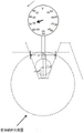
As shown in fig. 12, the detection condition is that the width of the slot of the worm to be detected is larger than that of the standard worm. And at the moment, the dial indicator deviates to the left, the tooth space width e 'of the worm to be measured is larger than the tooth space width e of the standard worm, the distance from the sphere center of the metal measuring ball head to the tooth root circle is recorded as delta d', the delta d is larger than the delta d ', the reading of the dial indicator is recorded as l, the difference delta between the delta d and the delta d' is the reading l of the dial indicator, and the change of the delta d is the reading of the dial indicator and the change of the tooth space width according to the geometric relationshipChange Δ e to a proportionality coefficient of k1The relationship (2) of (c). Therefore, the deviation of the tooth groove width of the standard worm and the worm to be measured is reflected as the reading l of the dial indicator.
Δd=ke>Δd' (6)
l=Δd'-Δd=δ=k1(e'-e)=k1Δe (7)
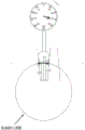
As shown in fig. 13, the detection condition is that the width of the slot of the worm to be detected is smaller than the width of the slot of the standard worm. And when the dial indicator deviates to the right, the tooth space width e 'of the worm to be measured is smaller than the tooth space width e of the standard worm, the distance from the sphere center of the metal measuring ball head to the tooth root circle is recorded as delta d', therefore, the delta d is smaller than the delta d ', the reading of the dial indicator is recorded as l', the difference delta 'between the delta d and the delta d' is the reading l 'of the dial indicator, and the change of the delta d, namely the reading of the dial indicator and the change of the tooth space width delta e', is obtained by a geometrical relationship, wherein the proportional coefficient of the change of the delta d is k2The relationship (2) of (c). Therefore, the deviation of the tooth groove width of the standard worm and the worm to be measured is reflected as the reading l' of the dial indicator.
Δd=ke<Δd' (8)
l'=Δd”-Δd=δ'=k2(e”-e)=k2Δe' (9)
The detection of the residual tooth space width of the worm to be detected can be carried out according to the principle method. If the reading of the dial indicator is within the allowable error range, the worm to be detected is a qualified product; and if the reading of the dial indicator is out of the allowable error range, the worm to be tested is an unqualified product.
The dial indicator and the metal measuring ball head used in the device are regularly calibrated, so that the comparison and measurement result of the width of the worm gear groove can trace to the national standard of the width of the gear groove.
The above description is only a preferred embodiment of the present invention, and is not intended to limit the present invention, and all simple modifications, changes and equivalent structural changes made to the above embodiment according to the technical spirit of the present invention still fall within the protection scope of the technical solution of the present invention.
Claims (3)
1. The utility model provides a worm tooth groove width contrast detection device which characterized in that:
the device comprises a mobile control module, a tested piece clamping module, a detection module and a supporting and fixing module;
the movement control module comprises an X-direction guide rail movement control module and a Z-direction upright post movement control module;
the X-direction guide rail movement control module comprises a measurement experiment pedestal, a left thimble frame and a right thimble frame, wherein the measurement experiment pedestal comprises a movable guide rail, a bakelite hand wheel and a bakelite nut;
the X-direction guide rail movement control module is mainly used for controlling the left thimble frame and the right thimble frame to move along the X direction, and adjusting a bakelite nut of the thimble frame to roughly adjust the position of the worm in the X direction so that a metal measuring ball head in the Z direction can be between two teeth of the worm; a thimble frame handle on the right thimble frame is used for controlling the right thimble to move left and right to load and unload the worm;
the bakelite handwheel is used for fine adjustment of the position of the movable guide rail;
the clamping module of the tested part is arranged on the left thimble frame and the right thimble frame, comprises a left thimble and a right thimble and is mainly used for fixing the worm in the X direction;
the Z-direction upright post movement control module comprises a measuring seat, a lifting nut and an upright post; the measuring seat is arranged on the upright post through a lifting nut, and the lifting of the measuring seat in the Z-axis direction can be realized by adjusting the lifting nut;
the detection module comprises a dial indicator, a metal measuring ball head, a metal connecting rod and an indicator frame, the indicator frame is arranged on the measuring seat and can be lifted up or put down by using an indicator frame handle, and the dial indicator is arranged on the indicator frame through a threaded through hole;
and worms with different tooth space widths are provided with metal measuring bulbs with different measuring diameters, the metal measuring bulbs are positioned at the tail ends of metal connecting rods, and the other ends of the metal connecting rods are connected with the dial indicator by virtue of threads.
2. A worm tooth groove width contrast detection method using the device of claim 1, characterized in that:
firstly, completing zero setting work before detecting the width of a tooth socket of a worm to be detected;
installing a standard worm between a left thimble frame and a right thimble frame, roughly adjusting the position of the standard worm relative to a metal measuring ball head to enable one tooth groove of the standard worm to be roughly positioned below the metal measuring ball head, clamping the standard worm by a left thimble and a right thimble, adjusting a lifting nut on a stand column to control the Z-direction height of a measuring seat, lifting a handle of the gauge frame, putting down a dial indicator to enable the metal measuring ball head to be in contact with the standard worm after the dial indicator is put down, finding a certain position of the metal measuring ball head on the standard worm to enable the reading of the dial indicator to be minimum, namely roughly positioning the center of the ball of the metal measuring ball head at a reference circle of two teeth of the standard worm, and adjusting the reading of the dial indicator to enable the reading;
secondly, mounting a worm to be tested;
putting down a meter frame handle, lifting up a dial indicator, releasing a thimble frame handle on a right thimble frame, detaching a standard worm, locking the thimble frame handle, mounting a worm to be measured on a left thimble and a right thimble, roughly adjusting the position of the worm to be measured relative to a metal measuring ball head, enabling a first tooth socket of the worm to be measured to be roughly positioned below the metal measuring ball head, locking the thimble frame handle of the right thimble frame, lifting up the meter frame handle, putting down the dial indicator, enabling the metal measuring ball head to be positioned between a first tooth and a second tooth, and adjusting a bakelite hand wheel to finish fine adjustment;
thirdly, comparing and detecting the width of the tooth groove;
observing the reading of the dial indicator, judging whether the reading is located at a zero position, if so, putting down the handle, lifting up the dial indicator, adjusting the position of the worm to be measured according to the second step mode to enable the second tooth socket of the worm to be measured to be approximately located below the metal measuring ball head, lifting up the handle, putting down the dial indicator to enable the measuring ball head to be located between the second tooth and the third tooth, finely adjusting a bakelite hand wheel, and similarly observing whether the reading of the dial indicator is located at the zero position, so that whether the second tooth socket width of the worm to be measured and the standard worm have deviation can be judged; the width of the other residual tooth grooves is measured in the same way, so that the width of each tooth groove of the worm to be detected is quickly detected; if the reading of the dial indicator is not at the zero position, the tooth groove width of the worm to be measured and the tooth groove width of the standard worm have deviation.
3. The worm tooth-groove width contrast detection method according to claim 2, characterized in that:
when the width of the tooth groove of the worm to be measured is detected, if the reading of the dial indicator deviates to the left or to the right, the width e 'of the tooth groove of the worm to be measured is larger than or smaller than the width e of the tooth groove of the standard worm, at the moment, the distance delta d' from the center of the metal measuring ball head to the tooth root circle of the worm to be measured is smaller than or larger than the distance delta d from the center of the metal measuring ball head to the tooth root circle of the standard worm, the reading of the dial indicator is marked as l, the difference delta between the delta d and the delta d 'is the reading l of the dial indicator, and the difference delta between the delta d and the delta d' and the change delta e of the tooth groove width are in the relationship that the proportionality coefficient is k:
l=Δd′-Δd=δ=k′(e′-e)=k′Δe。
Priority Applications (1)
| Application Number | Priority Date | Filing Date | Title |
|---|---|---|---|
| CN202011378427.7A CN112649191B (en) | 2020-11-30 | 2020-11-30 | Worm tooth groove width comparison detection device and method |
Applications Claiming Priority (1)
| Application Number | Priority Date | Filing Date | Title |
|---|---|---|---|
| CN202011378427.7A CN112649191B (en) | 2020-11-30 | 2020-11-30 | Worm tooth groove width comparison detection device and method |
Publications (2)
| Publication Number | Publication Date |
|---|---|
| CN112649191A true CN112649191A (en) | 2021-04-13 |
| CN112649191B CN112649191B (en) | 2022-11-29 |
Family
ID=75349875
Family Applications (1)
| Application Number | Title | Priority Date | Filing Date |
|---|---|---|---|
| CN202011378427.7A Active CN112649191B (en) | 2020-11-30 | 2020-11-30 | Worm tooth groove width comparison detection device and method |
Country Status (1)
| Country | Link |
|---|---|
| CN (1) | CN112649191B (en) |
Citations (10)
| Publication number | Priority date | Publication date | Assignee | Title |
|---|---|---|---|---|
| GB577218A (en) * | 1943-03-04 | 1946-05-09 | Kodak Ltd | Improvements in or relating to a gear testing machine |
| CN2847213Y (en) * | 2005-12-17 | 2006-12-13 | 江苏罡阳股份有限公司 | Internal and external structure relative position size measuring device for rack piston |
| CN201138186Y (en) * | 2007-11-23 | 2008-10-22 | 株洲齿轮有限责任公司 | Vertical gear inner spline rod interval checker |
| CN201772848U (en) * | 2010-07-13 | 2011-03-23 | 沪东重机有限公司 | Precision measuring tool used for detecting installation precision of drive worm bar and rack of machine tool |
| CN105627876A (en) * | 2015-12-18 | 2016-06-01 | 天津天海同步科技有限公司 | Internal spline effect tooth space width gage |
| WO2017151542A1 (en) * | 2016-03-01 | 2017-09-08 | Gleason Metrology Systems Comporation | Measurement of worm gears |
| CN206670520U (en) * | 2017-03-17 | 2017-11-24 | 上海新剑机电科技发展有限公司 | Worm screw path device for fast detecting |
| CN210981130U (en) * | 2020-01-15 | 2020-07-10 | 井陉矿务局工贸总公司 | Worm axis deviation measuring device |
| CN211060763U (en) * | 2019-12-30 | 2020-07-21 | 井陉矿务局工贸总公司 | Tooth space width checking device |
| CN111536858A (en) * | 2020-04-29 | 2020-08-14 | 大连创新零部件制造公司 | Hand-held comparison method worm rod span three-wire measuring instrument and measuring method |
-
2020
- 2020-11-30 CN CN202011378427.7A patent/CN112649191B/en active Active
Patent Citations (10)
| Publication number | Priority date | Publication date | Assignee | Title |
|---|---|---|---|---|
| GB577218A (en) * | 1943-03-04 | 1946-05-09 | Kodak Ltd | Improvements in or relating to a gear testing machine |
| CN2847213Y (en) * | 2005-12-17 | 2006-12-13 | 江苏罡阳股份有限公司 | Internal and external structure relative position size measuring device for rack piston |
| CN201138186Y (en) * | 2007-11-23 | 2008-10-22 | 株洲齿轮有限责任公司 | Vertical gear inner spline rod interval checker |
| CN201772848U (en) * | 2010-07-13 | 2011-03-23 | 沪东重机有限公司 | Precision measuring tool used for detecting installation precision of drive worm bar and rack of machine tool |
| CN105627876A (en) * | 2015-12-18 | 2016-06-01 | 天津天海同步科技有限公司 | Internal spline effect tooth space width gage |
| WO2017151542A1 (en) * | 2016-03-01 | 2017-09-08 | Gleason Metrology Systems Comporation | Measurement of worm gears |
| CN206670520U (en) * | 2017-03-17 | 2017-11-24 | 上海新剑机电科技发展有限公司 | Worm screw path device for fast detecting |
| CN211060763U (en) * | 2019-12-30 | 2020-07-21 | 井陉矿务局工贸总公司 | Tooth space width checking device |
| CN210981130U (en) * | 2020-01-15 | 2020-07-10 | 井陉矿务局工贸总公司 | Worm axis deviation measuring device |
| CN111536858A (en) * | 2020-04-29 | 2020-08-14 | 大连创新零部件制造公司 | Hand-held comparison method worm rod span three-wire measuring instrument and measuring method |
Non-Patent Citations (1)
| Title |
|---|
| 程红: "多头蜗杆轴向齿距的测量及其对加工的指导意义", 《计量技术》 * |
Also Published As
| Publication number | Publication date |
|---|---|
| CN112649191B (en) | 2022-11-29 |
Similar Documents
| Publication | Publication Date | Title |
|---|---|---|
| CN105403128A (en) | Integrated measurement instrument of inner-ring large flange of tapered roller bearing | |
| CN111879512A (en) | Worm gear meshing detection device | |
| CN210464336U (en) | Angle adjusting workbench for measuring angle of flange of bearing inner ring | |
| CN115235402A (en) | High-precision detection machine | |
| CN111207656A (en) | Rapid metering device and metering method for tooth profile of cycloidal gear of RV reducer | |
| CN104075636B (en) | A kind of device measuring disk hole position degree | |
| CN112649191B (en) | Worm tooth groove width comparison detection device and method | |
| CN210135858U (en) | Comprehensive calibration device for wide-range length measurement measuring tool based on laser interference | |
| CN219531923U (en) | Long shaft piece axiality quick detection device | |
| CN111623693A (en) | Cylinder roundness detection tool | |
| CN108615546B (en) | Angle adjusting device for measuring residual stress of gear tooth root | |
| CN216898709U (en) | High-precision straightness detection tool | |
| CN212844334U (en) | Worm gear meshing detection device | |
| CN111854562B (en) | Universal glass lifter guide rail detection tool and detection method | |
| CN212432024U (en) | Precision part symmetry detection device | |
| CN110345837B (en) | Comprehensive checking device of wide-range length measuring tool based on laser interference | |
| CN208155199U (en) | A kind of axial dimension measuring device | |
| CN219869591U (en) | Three-coordinate measuring gauge for electric vehicle frame | |
| CN219776607U (en) | Quick detection tool for flat square symmetry degree of input shaft of automobile steering gear | |
| CN219403542U (en) | Y-direction hole detection device for milling machine screw nut seat | |
| CN112629367B (en) | Worm tooth profile and tooth thickness detection device and method | |
| CN112923830B (en) | Device and method for measuring space size of balancing rod | |
| CN220708278U (en) | Online detection device for profile of valve rocker assembly support surface and center height | |
| CN211651463U (en) | High-precision detection device for measuring outer diameter | |
| CN220018433U (en) | Flatness detector |
Legal Events
| Date | Code | Title | Description |
|---|---|---|---|
| PB01 | Publication | ||
| PB01 | Publication | ||
| SE01 | Entry into force of request for substantive examination | ||
| SE01 | Entry into force of request for substantive examination | ||
| GR01 | Patent grant | ||
| GR01 | Patent grant |