CN216898709U - High-precision straightness detection tool - Google Patents
High-precision straightness detection tool Download PDFInfo
- Publication number
- CN216898709U CN216898709U CN202123296686.8U CN202123296686U CN216898709U CN 216898709 U CN216898709 U CN 216898709U CN 202123296686 U CN202123296686 U CN 202123296686U CN 216898709 U CN216898709 U CN 216898709U
- Authority
- CN
- China
- Prior art keywords
- straightness
- sliding
- universal meter
- screw rod
- dial indicator
- Prior art date
- Legal status (The legal status is an assumption and is not a legal conclusion. Google has not performed a legal analysis and makes no representation as to the accuracy of the status listed.)
- Active
Links
Images

Abstract
The utility model relates to a high-precision straightness detection tool which is used for measuring the straightness of a long-rod screw rod and comprises a fixed base, a lever dial indicator, a mechanical universal meter frame and two article placing frames, wherein the fixed base comprises a pedestal, a sliding groove and a blocking groove, and the sliding groove and the blocking groove are formed in the pedestal; the lever dial indicator is arranged on the mechanical universal meter frame and used for measuring straightness; the mechanical universal meter frame is connected with the blocking groove in a sliding manner; two supporter sliding connection the spout for bear the weight of the screw rod of being surveyed. The utility model greatly improves the measurement precision of the long rod type screw rod and improves the automation degree and the working efficiency to the maximum extent.
Description
Technical Field
The utility model relates to an automobile part detection tool, in particular to a detection tool for detecting an automobile long rod type screw rod, which is simple and reliable in structure and convenient to realize, and can directly acquire the straightness of the detected screw rod after the screw rod is processed.
Background
The continuous improvement of people's living standard, the car has almost become indispensable articles for use, and the continuous development of science and technology, the continuous progress of technique also makes people to the security of car, travelling comfort and convenience more and more high. The screw for fastening the automobile plays an important role in automobile assembly, and once a product fails, the screw can possibly cause the falling of automobile parts and the bad results of the damage and the disintegration of the whole automobile, so that higher requirements are put forward on the locking performance of the screw. With the development of the automobile industry, the demand for screw fasteners is increasing, and meanwhile, the requirements for the quality of screw products are higher and higher, and various sizes, performances and stability of screws are particularly important.
When the screw rod is formed by cold heading in the prior art, the straightness of the screw rod is detected by the groove gauge, the groove gauge cannot accurately read out a numerical value, and although a qualified product detected by the groove gauge is within an allowable range, the qualified product still has a lifting place.
Therefore, the problem that the straightness of the long rod type screw cannot be accurately read in the prior art needs to be improved urgently, and the research, development and improvement significance of the long rod type screw detection gauge is great.
SUMMERY OF THE UTILITY MODEL
The utility model aims to provide a detection tool which is simple and reliable in structure and convenient to implement, and can be used for directly acquiring the straightness of a long rod screw to be detected after the long rod screw is processed, so as to solve the problems in the prior art.
In order to achieve the purpose, the utility model adopts the following technical scheme:
a high-precision straightness detection tool is used for measuring the straightness of a long-rod screw and comprises a fixed base, a lever dial indicator, a mechanical universal meter frame and two article placing frames, wherein the fixed base comprises a pedestal, a sliding groove and a blocking groove, and the sliding groove and the blocking groove are formed in the pedestal; the lever dial indicator is arranged on the mechanical universal meter frame and used for measuring straightness; the mechanical universal meter frame is connected with the blocking groove in a sliding manner; two supporter sliding connection the spout for bear the weight of the screw rod of being surveyed.
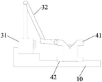
According to the high-precision straightness detection tool in the preferred embodiment of the utility model, the mechanical universal meter frame comprises a support part and a movable foot part, the movable foot part is arranged on the support part, and the lever dial indicator is connected with the movable foot part.
According to the high-precision straightness detection tool in the preferred embodiment of the utility model, the rack comprises a V-shaped rack part and a sliding block part, and the V-shaped rack part is arranged above the sliding block part; the sliding block part is connected with the sliding groove in a sliding mode.
The design idea of this application is, designs out the detection utensil of examining of the straightness accuracy of a stock class screw rod, when several kinds of specification products of mass production, except that whether up to standard of detection straightness accuracy, still need know the numerical value of deviation for processing and detection means combine together, as the improvement of automatic technology process, improve work efficiency, and guarantee measuring result's credibility.
Due to the adoption of the technical scheme, the utility model has the following advantages and effects:
firstly, the structure is simple and the use is convenient;
secondly, the straightness of long rod type screw rods with different lengths can be detected, and the universality is strong;
third, this application makes processing and detection means combine together, very big improvement stock class screw rod's measurement accuracy, furthest's improvement degree of automation and work efficiency.
Of course, it is not necessary for any particular embodiment of the inventive concept to be implemented to achieve all of the above technical effects at the same time.
Drawings
FIG. 1 is a schematic perspective view of a detection tool of the present application;
FIG. 2 is a left side schematic view of FIG. 1;
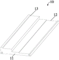
fig. 3 is a schematic view of a fixing base according to the present application.
Detailed Description
The utility model is described in detail below with reference to the accompanying drawings;
please refer to fig. 1, fig. 2 and fig. 3, a schematic perspective view, a schematic left-view and a schematic fixed base of the inspection tool of the present application; the high-precision straightness detection tool is used for measuring the straightness of a long rod type screw 1 and comprises a fixed base 10, a lever dial indicator 20, a mechanical universal meter frame 30 and two article holders 40, wherein the fixed base 10 comprises a pedestal 11, and a sliding groove 12 and a blocking groove 13 which are formed in the pedestal 11; the lever percentage table 20 is arranged on the mechanical universal meter frame 30 and used for measuring straightness, as shown in the figure, the lever percentage table 20 comprises an indicating meter and a measuring head, the measuring range of the lever percentage table 20 is +/-0.4, the displacement of the measuring head is converted into the angular displacement of a pointer on a dial plate of the indicating meter through a mechanical rotating system, and a measuring tool with uniform scales is arranged on the circumference of the dial plate.
As shown in fig. 1 and 2, the mechanical gimbal table 30 is slidably connected to the blocking slot 13, the direction of the measurement movement in this application refers to the direction in which the mechanical gimbal table 30 slides along the blocking slot 13, and the mechanical gimbal table 30 is a magnetic table, and the magnetic design makes the mechanical gimbal table 30 stable on the blocking slot 13 without tilting and can maintain a consistent direction of travel; two supporter 40 sliding connection spout 12 for bear the weight of the screw rod of being surveyed, two supporter 40's interval is according to the screw rod length adjustment of actually being surveyed, and the both ends that will be surveyed the screw rod are placed in principle on supporter 40. In fig. 2 and 3, the blocking groove 13 and the sliding groove 12 are arranged on the pedestal 11 in parallel, and when the measuring head is perpendicular to the blocking groove 13, the measuring movement direction is perpendicular to the center line of the measuring head, so that the detection accuracy can be improved.
As shown in fig. 2, the mechanical gimbal table 30 includes a supporting portion 31 and a movable leg portion 32, the movable leg portion 32 is disposed on the supporting portion 31, the lever dial indicator 20 is connected to the movable leg portion 32, and in the figure, the movable leg portion 32 is a two-segment connecting column structure, so as to adjust a pointing position; the lever dial indicator 20 is connected with the movable foot part 32 in a manner that the lever dial indicator 20 is rotatably connected with the movable foot part 32 through a meter seat; the stand portion 31 is magnetic, and the base 11 is made of steel, so that the mechanical universal meter stand 30 is stably magnetically attracted to the catch groove 13 and does not tilt.
In fig. 2, in the embodiment of the present application, the rack 40 includes a V-shaped rack portion 41 and a slider portion 42, but the present application is not limited thereto, and the present application should be within the protection scope as long as the tested screw can be stably connected; the V-shaped frame part 41 is arranged above the sliding block part 42, the V-shaped frame part 41 and the sliding block part 42 are integrally formed, the V-shaped frame part 41 is a V-shaped tool, the V-shaped frame part 41 is used as an auxiliary tool for positioning of long rod type screw rod detection in the application, and the V-shaped frame part 41 enables the axial lead of the long rod type screw rod to be parallel to the working surface of the pedestal 11 so as to be aligned and detected; in addition, the sliding block part 42 is connected with the sliding groove 12 in a sliding mode, the sliding block part 42 slides in the sliding groove 12, deflection is avoided, the distance can be adjusted according to different screw rod lengths, and the universality is high.
The straightness detection check tool has the following operation modes:
1. the lever dial indicator 20 is fixed on the reliable mechanical universal meter frame 30, the mechanical universal meter frame 30 is close to the blocking groove 13, the position of the lever dial indicator 20 is adjusted at the same time, a measuring head is located at the middle position of the lower surface of the tested screw, whether the lever dial indicator 20 is clamped firmly is checked before measurement, the measuring head of the lever dial indicator 20 is pulled and contacted with the tested screw for multiple times, and whether the repeated indicated values are the same is observed;
2. in the preparation process, the measuring head cannot be impacted by the screw to be measured so as to avoid influencing the measurement precision or damaging the indicating gauge; in order to maintain a certain initial measuring force, when the measuring head is in contact with the measured screw rod, the compression amount of the measuring head should be 0.3-0.5 mm;
3. the measuring head is not required to be oiled, so that oil dirt is prevented from entering the indicating meter and the sensitivity of the lever dial indicator 20 is not influenced;
4. the measuring head of the lever dial indicator 20 is perpendicular to the surface of the screw to be measured, so that errors are avoided;
5. during measurement, the mechanical universal meter bracket 30 slides close to the blocking groove 13, and the maximum deflection position of a pointer on the indicating meter is observed, wherein the maximum deflection position is the lowest point of a measured screw rod; and detecting the straightness of the tested screw (the maximum deformation position of the tested screw) at the position, uniformly rotating for a circle along the head of the tested screw, observing the deflection position of a pointer of the indicating table, recording a detection result, filling a straightness detection recording table, and completing the detection of the rest tested screws according to the process.
It should be noted that in the description of the embodiments of the present application, the terms "front, back", "left, right", "upper, lower", and the like indicate orientations or positional relationships based on those shown in the drawings, which are only for convenience of description and simplification of description, but do not indicate or imply that the referred device or element must have a specific orientation, be configured in a specific orientation, and operate, and thus, should not be construed as limiting the present application. The terms "mounted," "connected," and "coupled" are to be construed broadly and may, for example, be fixedly coupled, detachably coupled, or integrally coupled; they may be connected directly or indirectly through intervening media, or they may be interconnected between two elements. The specific meaning of the above terms in the present application can be understood in a specific case by those of ordinary skill in the art.
Due to the adoption of the technical scheme, the utility model has the following advantages and effects:
firstly, the structure is simple and the use is convenient;
secondly, the straightness of long rod type screw rods with different lengths can be detected, and the universality is strong;
third, this application makes processing and detection means combine together, very big improvement stock class screw rod's measurement accuracy, furthest's improvement degree of automation and work efficiency.
The above disclosure is only for the specific embodiments of the present invention, but the present invention is not limited thereto, and any variations that can be made by those skilled in the art are intended to fall within the scope of the present invention.
Claims (3)
1. The utility model provides a high accuracy straightness accuracy detection examines utensil for measure the straightness accuracy of stock class screw rod, its characterized in that: the straightness detection gauge comprises a fixed base, a lever dial indicator, a mechanical universal meter frame and two article placing frames, wherein the fixed base comprises a pedestal, and a sliding groove and a blocking groove which are formed in the pedestal; wherein the content of the first and second substances,
the lever dial indicator is arranged on the mechanical universal meter frame and used for measuring straightness;
the mechanical universal meter frame is connected with the blocking groove in a sliding manner;
two supporter sliding connection the spout for bear the weight of the screw rod of being surveyed.
2. The high-precision straightness detection tool according to claim 1, wherein: the mechanical universal meter frame comprises a support part and a movable foot part, wherein the movable foot part is arranged on the support part, and the lever dial indicator is connected with the movable foot part.
3. The high-precision straightness detection tool according to claim 2, wherein: the commodity shelf comprises a V-shaped frame part and a sliding block part, and the V-shaped frame part is arranged above the sliding block part; the sliding block part is connected with the sliding groove in a sliding mode.
Priority Applications (1)
| Application Number | Priority Date | Filing Date | Title |
|---|---|---|---|
| CN202123296686.8U CN216898709U (en) | 2021-12-24 | 2021-12-24 | High-precision straightness detection tool |
Applications Claiming Priority (1)
| Application Number | Priority Date | Filing Date | Title |
|---|---|---|---|
| CN202123296686.8U CN216898709U (en) | 2021-12-24 | 2021-12-24 | High-precision straightness detection tool |
Publications (1)
| Publication Number | Publication Date |
|---|---|
| CN216898709U true CN216898709U (en) | 2022-07-05 |
Family
ID=82208862
Family Applications (1)
| Application Number | Title | Priority Date | Filing Date |
|---|---|---|---|
| CN202123296686.8U Active CN216898709U (en) | 2021-12-24 | 2021-12-24 | High-precision straightness detection tool |
Country Status (1)
| Country | Link |
|---|---|
| CN (1) | CN216898709U (en) |
Cited By (1)
| Publication number | Priority date | Publication date | Assignee | Title |
|---|---|---|---|---|
| CN115876061A (en) * | 2023-02-01 | 2023-03-31 | 成都正西萨凡智能设备有限公司 | Detection device and detection method for slider machining surface of bending machine |
-
2021
- 2021-12-24 CN CN202123296686.8U patent/CN216898709U/en active Active
Cited By (1)
| Publication number | Priority date | Publication date | Assignee | Title |
|---|---|---|---|---|
| CN115876061A (en) * | 2023-02-01 | 2023-03-31 | 成都正西萨凡智能设备有限公司 | Detection device and detection method for slider machining surface of bending machine |
Similar Documents
| Publication | Publication Date | Title |
|---|---|---|
| CN101776429B (en) | Check tool for measuring axial length of crank shaft and application thereof | |
| CN216898709U (en) | High-precision straightness detection tool | |
| CN110986740A (en) | Circular hole brake shoe outer circular arc comprehensive checking fixture | |
| CN111351440A (en) | Measuring device based on grating ruler | |
| CN110779418A (en) | Method for measuring length of cone on line by double meters | |
| CN109974556A (en) | General measuring instrument and measurement method | |
| CN215261587U (en) | Device for measuring inner cone | |
| CN211084984U (en) | Dial indicator calibrating device | |
| CN209961151U (en) | Coaxiality detection device | |
| CN2141554Y (en) | Two-stage measuring displacement measurer | |
| CN219015165U (en) | Device for detecting length and size of limited space | |
| CN214842890U (en) | Comprehensive measuring device for shaft parts | |
| CN212512845U (en) | Automobile half-bridge groove inner diameter gauge | |
| CN218994240U (en) | Mechanism for rapidly detecting maximum appearance of part | |
| CN217236708U (en) | Anvil symmetry verifying attachment | |
| CN217122641U (en) | Measuring tool | |
| CN216745867U (en) | Inner gear ring M value measuring device | |
| CN219223569U (en) | Wall thickness detection device of shaft fork forging | |
| CN220288608U (en) | Inclination detection device | |
| CN114046713B (en) | Leveling device suitable for height difference of inner and outer parts | |
| CN216205995U (en) | Self-centering hole position and groove size measuring device | |
| CN112923830B (en) | Device and method for measuring space size of balancing rod | |
| CN112649191B (en) | Worm tooth groove width comparison detection device and method | |
| CN213456039U (en) | High-precision heavy spring stiffness detection clamp | |
| CN213778974U (en) | Multifunctional roughness measuring jig |
Legal Events
| Date | Code | Title | Description |
|---|---|---|---|
| GR01 | Patent grant | ||
| GR01 | Patent grant |