CN112610652B - Electromechanical device damping device - Google Patents
Electromechanical device damping device Download PDFInfo
- Publication number
- CN112610652B CN112610652B CN202110080205.5A CN202110080205A CN112610652B CN 112610652 B CN112610652 B CN 112610652B CN 202110080205 A CN202110080205 A CN 202110080205A CN 112610652 B CN112610652 B CN 112610652B
- Authority
- CN
- China
- Prior art keywords
- block
- base
- fixedly connected
- connecting seat
- magnet
- Prior art date
- Legal status (The legal status is an assumption and is not a legal conclusion. Google has not performed a legal analysis and makes no representation as to the accuracy of the status listed.)
- Expired - Fee Related
Links
- 238000013016 damping Methods 0.000 title claims abstract description 38
- 230000007246 mechanism Effects 0.000 claims abstract description 40
- 238000001179 sorption measurement Methods 0.000 claims abstract description 10
- 230000005540 biological transmission Effects 0.000 claims description 9
- 239000000428 dust Substances 0.000 claims description 4
- 241000252254 Catostomidae Species 0.000 claims description 2
- 230000005389 magnetism Effects 0.000 claims description 2
- 238000009434 installation Methods 0.000 abstract description 4
- 238000004519 manufacturing process Methods 0.000 abstract description 3
- 230000008878 coupling Effects 0.000 abstract description 2
- 238000010168 coupling process Methods 0.000 abstract description 2
- 238000005859 coupling reaction Methods 0.000 abstract description 2
- 230000035939 shock Effects 0.000 description 11
- 230000000694 effects Effects 0.000 description 5
- 230000002035 prolonged effect Effects 0.000 description 3
- 238000010521 absorption reaction Methods 0.000 description 2
- 238000005516 engineering process Methods 0.000 description 2
- 230000006872 improvement Effects 0.000 description 2
- 230000001174 ascending effect Effects 0.000 description 1
- 230000009286 beneficial effect Effects 0.000 description 1
- 230000007123 defense Effects 0.000 description 1
- 238000010586 diagram Methods 0.000 description 1
- 238000002347 injection Methods 0.000 description 1
- 239000007924 injection Substances 0.000 description 1
- 230000004048 modification Effects 0.000 description 1
- 238000012986 modification Methods 0.000 description 1
- 239000000243 solution Substances 0.000 description 1
Images


Classifications
-
- F—MECHANICAL ENGINEERING; LIGHTING; HEATING; WEAPONS; BLASTING
- F16—ENGINEERING ELEMENTS AND UNITS; GENERAL MEASURES FOR PRODUCING AND MAINTAINING EFFECTIVE FUNCTIONING OF MACHINES OR INSTALLATIONS; THERMAL INSULATION IN GENERAL
- F16F—SPRINGS; SHOCK-ABSORBERS; MEANS FOR DAMPING VIBRATION
- F16F15/00—Suppression of vibrations in systems; Means or arrangements for avoiding or reducing out-of-balance forces, e.g. due to motion
- F16F15/02—Suppression of vibrations of non-rotating, e.g. reciprocating systems; Suppression of vibrations of rotating systems by use of members not moving with the rotating systems
- F16F15/03—Suppression of vibrations of non-rotating, e.g. reciprocating systems; Suppression of vibrations of rotating systems by use of members not moving with the rotating systems using magnetic or electromagnetic means
-
- F—MECHANICAL ENGINEERING; LIGHTING; HEATING; WEAPONS; BLASTING
- F16—ENGINEERING ELEMENTS AND UNITS; GENERAL MEASURES FOR PRODUCING AND MAINTAINING EFFECTIVE FUNCTIONING OF MACHINES OR INSTALLATIONS; THERMAL INSULATION IN GENERAL
- F16F—SPRINGS; SHOCK-ABSORBERS; MEANS FOR DAMPING VIBRATION
- F16F15/00—Suppression of vibrations in systems; Means or arrangements for avoiding or reducing out-of-balance forces, e.g. due to motion
- F16F15/02—Suppression of vibrations of non-rotating, e.g. reciprocating systems; Suppression of vibrations of rotating systems by use of members not moving with the rotating systems
- F16F15/023—Suppression of vibrations of non-rotating, e.g. reciprocating systems; Suppression of vibrations of rotating systems by use of members not moving with the rotating systems using fluid means
-
- F—MECHANICAL ENGINEERING; LIGHTING; HEATING; WEAPONS; BLASTING
- F16—ENGINEERING ELEMENTS AND UNITS; GENERAL MEASURES FOR PRODUCING AND MAINTAINING EFFECTIVE FUNCTIONING OF MACHINES OR INSTALLATIONS; THERMAL INSULATION IN GENERAL
- F16F—SPRINGS; SHOCK-ABSORBERS; MEANS FOR DAMPING VIBRATION
- F16F15/00—Suppression of vibrations in systems; Means or arrangements for avoiding or reducing out-of-balance forces, e.g. due to motion
- F16F15/02—Suppression of vibrations of non-rotating, e.g. reciprocating systems; Suppression of vibrations of rotating systems by use of members not moving with the rotating systems
- F16F15/04—Suppression of vibrations of non-rotating, e.g. reciprocating systems; Suppression of vibrations of rotating systems by use of members not moving with the rotating systems using elastic means
- F16F15/046—Suppression of vibrations of non-rotating, e.g. reciprocating systems; Suppression of vibrations of rotating systems by use of members not moving with the rotating systems using elastic means using combinations of springs of different kinds
-
- F—MECHANICAL ENGINEERING; LIGHTING; HEATING; WEAPONS; BLASTING
- F16—ENGINEERING ELEMENTS AND UNITS; GENERAL MEASURES FOR PRODUCING AND MAINTAINING EFFECTIVE FUNCTIONING OF MACHINES OR INSTALLATIONS; THERMAL INSULATION IN GENERAL
- F16F—SPRINGS; SHOCK-ABSORBERS; MEANS FOR DAMPING VIBRATION
- F16F15/00—Suppression of vibrations in systems; Means or arrangements for avoiding or reducing out-of-balance forces, e.g. due to motion
- F16F15/02—Suppression of vibrations of non-rotating, e.g. reciprocating systems; Suppression of vibrations of rotating systems by use of members not moving with the rotating systems
- F16F15/04—Suppression of vibrations of non-rotating, e.g. reciprocating systems; Suppression of vibrations of rotating systems by use of members not moving with the rotating systems using elastic means
- F16F15/06—Suppression of vibrations of non-rotating, e.g. reciprocating systems; Suppression of vibrations of rotating systems by use of members not moving with the rotating systems using elastic means with metal springs
-
- F—MECHANICAL ENGINEERING; LIGHTING; HEATING; WEAPONS; BLASTING
- F16—ENGINEERING ELEMENTS AND UNITS; GENERAL MEASURES FOR PRODUCING AND MAINTAINING EFFECTIVE FUNCTIONING OF MACHINES OR INSTALLATIONS; THERMAL INSULATION IN GENERAL
- F16F—SPRINGS; SHOCK-ABSORBERS; MEANS FOR DAMPING VIBRATION
- F16F15/00—Suppression of vibrations in systems; Means or arrangements for avoiding or reducing out-of-balance forces, e.g. due to motion
- F16F15/02—Suppression of vibrations of non-rotating, e.g. reciprocating systems; Suppression of vibrations of rotating systems by use of members not moving with the rotating systems
- F16F15/04—Suppression of vibrations of non-rotating, e.g. reciprocating systems; Suppression of vibrations of rotating systems by use of members not moving with the rotating systems using elastic means
- F16F15/08—Suppression of vibrations of non-rotating, e.g. reciprocating systems; Suppression of vibrations of rotating systems by use of members not moving with the rotating systems using elastic means with rubber springs ; with springs made of rubber and metal
-
- F—MECHANICAL ENGINEERING; LIGHTING; HEATING; WEAPONS; BLASTING
- F16—ENGINEERING ELEMENTS AND UNITS; GENERAL MEASURES FOR PRODUCING AND MAINTAINING EFFECTIVE FUNCTIONING OF MACHINES OR INSTALLATIONS; THERMAL INSULATION IN GENERAL
- F16M—FRAMES, CASINGS OR BEDS OF ENGINES, MACHINES OR APPARATUS, NOT SPECIFIC TO ENGINES, MACHINES OR APPARATUS PROVIDED FOR ELSEWHERE; STANDS; SUPPORTS
- F16M5/00—Engine beds, i.e. means for supporting engines or machines on foundations
-
- Y—GENERAL TAGGING OF NEW TECHNOLOGICAL DEVELOPMENTS; GENERAL TAGGING OF CROSS-SECTIONAL TECHNOLOGIES SPANNING OVER SEVERAL SECTIONS OF THE IPC; TECHNICAL SUBJECTS COVERED BY FORMER USPC CROSS-REFERENCE ART COLLECTIONS [XRACs] AND DIGESTS
- Y02—TECHNOLOGIES OR APPLICATIONS FOR MITIGATION OR ADAPTATION AGAINST CLIMATE CHANGE
- Y02E—REDUCTION OF GREENHOUSE GAS [GHG] EMISSIONS, RELATED TO ENERGY GENERATION, TRANSMISSION OR DISTRIBUTION
- Y02E10/00—Energy generation through renewable energy sources
- Y02E10/70—Wind energy
- Y02E10/72—Wind turbines with rotation axis in wind direction
Landscapes
- Engineering & Computer Science (AREA)
- General Engineering & Computer Science (AREA)
- Physics & Mathematics (AREA)
- Mechanical Engineering (AREA)
- Acoustics & Sound (AREA)
- Aviation & Aerospace Engineering (AREA)
- Chemical & Material Sciences (AREA)
- Combustion & Propulsion (AREA)
- Electromagnetism (AREA)
- Vibration Prevention Devices (AREA)
- Combined Devices Of Dampers And Springs (AREA)
- Springs (AREA)
Abstract
The invention relates to the technical field of mechanical manufacturing, in particular to an electromechanical equipment damping device, which comprises a base, wherein a connecting seat is arranged on the upper side of the base, a first damping mechanism is arranged between the connecting seat and the base, a second damping mechanism used for being connected with an installation plate is arranged on the inner side of the connecting seat, and an adsorption mechanism used for fixing a device is arranged on the inner side of the base. Through setting up coupling mechanism, utilize third spring and second rubber pad, can further promote the shock-absorbing capacity of equipment.
Description
Technical Field
The invention relates to the technical field of mechanical manufacturing, in particular to a damping device for electromechanical equipment.
Background
Along with the continuous improvement of the living standard of people, people have more and more demands on electromechanical equipment in daily life, the electromechanical equipment generally refers to machinery, electrical appliances and electrical automation equipment, the electromechanical equipment from vehicles to various household appliances, computers, printers and the like becomes indispensable electromechanical equipment in the life of people, the advanced electromechanical equipment not only can greatly improve the labor productivity, reduce the labor intensity, improve the production environment and finish the work which can not be finished by manpower, but also has direct and important influence on the development of the whole national economy, the improvement of science and technology and national defense strength as one of national industrial foundations, and is also an important mark for measuring the national science and technology level and comprehensive national strength.
The electromechanical device during operation can take place slightly to shake, if not effective shock attenuation, can seriously shorten electromechanical device's life, also can cause serious noise pollution, and current electromechanical device's damping device structure is fairly simple, and the shock attenuation effect is poor, often can only carry out the shock attenuation to the single direction, consequently, to above current situation, urgent need develop an electromechanical device damping device to overcome not enough in the current practical application.
Disclosure of Invention
The present invention is directed to a damping device for an electromechanical device, which solves the above problems of the prior art.
In order to achieve the purpose, the invention provides the following technical scheme:
the electromechanical device damping device comprises a base, wherein a connecting seat is arranged on the upper side of the base, a first damping mechanism is arranged between the connecting seat and the base, a second damping mechanism used for being connected with a mounting plate is arranged on the inner side of the connecting seat, and an adsorption mechanism used for fixing the electromechanical device is arranged on the inner side of the base.
As a further scheme of the invention: first damper includes that a plurality of fixed connection set up the guide bar in the connecting seat bottom, guide bar and base sliding connection, guide bar bottom fixed connection is provided with the limiting plate, the guide bar is located between base and the connecting seat the part outside and is provided with first spring, connecting seat bottom fixed connection is provided with first magnet, first magnet downside is provided with the second magnet with base fixed connection, first magnet is the same with the relative one side magnetism of second magnet, be provided with respectively in the first magnet and the second magnet outside with connecting seat and base fixed connection's first rubber pad.
As a further scheme of the invention: the adsorption mechanism comprises a bottom plate fixedly connected with the bottom of the inner side of the base, an air guide groove is formed in the inner side of the bottom plate, a plurality of suckers communicated with the air guide groove are arranged at the bottom end of the base, a branch pipe is fixedly connected between the left end and the right end of the bottom plate and the base, a valve is fixedly connected with the inner side of the joint of the branch pipe and the base, an air pump is arranged on the top of the bottom plate in a bolted connection mode, the input end of the air pump is connected with the air guide groove, and the output end of the air pump is connected with a buffer mechanism arranged at the tops of the left end and the right end of the bottom plate through an air guide pipe.
As a further scheme of the invention: buffer gear includes that fixed connection sets up the connecting block at both ends top about the bottom plate, the inboard fixed connection of air duct and connecting block junction is provided with the check valve, the connecting block is close to the inboard sliding connection of air duct one end and is provided with the piston, the piston is kept away from about air duct one end both sides all be provided with connecting block fixed connection's locating piece, the piston is close to locating piece one side fixed connection and is provided with the wedge, wedge top butt be provided with connecting seat fixed connection's depression bar, the air duct downside is provided with the blast pipe with connecting block fixed connection, the inboard fixed connection of blast pipe is provided with the relief valve, both ends all are provided with the gas outlet about the base, the inboard connection of gas outlet can be dismantled and be provided with the dust screen.
As a further scheme of the invention: the second damping mechanism comprises an opening arranged at the top end of the connecting seat, a supporting block is arranged on the inner side of the opening, the bottom end of the supporting block is connected with a sliding block in a sliding mode on the inner side of the connecting seat, a plurality of fixed blocks fixedly connected with the connecting seat are arranged on the outer side of the sliding block, a limiting block is arranged on the inner side of the fixed block in a sliding mode, a second spring is arranged between the limiting block and the fixed block in a fixed mode, a movable block slidably connected with the fixed block is arranged on the other end of the limiting block in a fixed mode, a baffle is arranged on the movable block close to one side of the sliding block in a fixed mode, and a connecting mechanism is arranged between the supporting block and the mounting plate.
As a further scheme of the invention: the connecting mechanism comprises a plurality of push rods which are arranged on the inner side of the supporting block in a sliding connection mode, a third spring is fixedly connected between the push rods and the supporting block, a transmission rod is hinged to the inner side of one end, far away from the supporting block, of each push rod, the other end of the transmission rod is hinged to a transmission block which is fixedly connected and arranged at the bottom of the mounting plate, and a second rubber pad is fixedly connected to the top of the supporting block.
As a further scheme of the invention: the upper side and the lower side of the push rod are fixedly connected with guide blocks, and the guide blocks are connected with guide grooves arranged on the inner sides of the supporting blocks in a sliding mode.
Compared with the prior art, the invention has the beneficial effects that:
1. by arranging the first damping mechanism, longitudinal impact force applied to the device during operation can be absorbed by utilizing the first spring, the first magnet and the second magnet, and meanwhile, by arranging the first rubber pad, direct collision between the connecting seat and the base can be avoided, so that the service life of the first damping mechanism is prolonged;
2. the adsorption mechanism is arranged, so that the stability of the device after installation can be improved, the buffer mechanism is arranged, the air pump is used for injecting air into the connecting block, the piston is driven by air pressure to enable the wedge block to be abutted against the pressure rod, when the connecting seat moves downwards due to vibration, the pressure of the pressure rod on the wedge block can accelerate the air to be discharged from the exhaust pipe, so that the descending speed of the connecting seat is reduced, the device is further damped, and meanwhile, the anti-seismic performance of the device can be adjusted by controlling the air flow of the air pump;
3. through setting up second damper, utilize a plurality of second springs, can absorb the impact force on the horizontal direction that the device received to make the device realize omnidirectional shock attenuation, promoted the shock attenuation effect of device greatly, through setting up coupling mechanism, utilize third spring and second rubber pad, can further lifting means's shock-absorbing capacity, guarantee the steady operation of equipment.
Drawings
Fig. 1 is a schematic structural view of a shock absorbing device for an electromechanical apparatus.
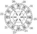
Fig. 2 is a top view of a connecting seat in the damping device of the electromechanical device.
Fig. 3 is an enlarged schematic view of a portion a in fig. 1.
Fig. 4 is a schematic structural diagram of a connecting seat in the damping device of the electromechanical device.
In the figure: 1-base, 2-connecting base, 3-mounting plate, 4-fixing plate, 5-base plate, 6-air guide groove, 7-suction cup, 8-branch pipe, 9-air pump, 10-air guide pipe, 11-connecting block, 12-air exhaust pipe, 13-air outlet, 14-dust screen, 15-guide rod, 16-limiting plate, 17-first spring, 18-first magnet, 19-first rubber pad, 20-sliding block, 21-supporting block, 22-baffle, 23-fixing block, 24-limiting block, 25-movable block, 26-second spring, 27-opening, 28-second rubber pad, 29-driving block, 30-push rod, 31-third spring, 32-driving rod, 33-pressure rod, 34-piston, 35-positioning block, 36-wedge block.
Detailed Description
The technical solution of the present patent will be described in further detail with reference to the following embodiments.
Reference will now be made in detail to embodiments of the present patent, examples of which are illustrated in the accompanying drawings, wherein like or similar reference numerals refer to the same or similar elements or elements having the same or similar function throughout. The embodiments described below with reference to the drawings are exemplary only for the purpose of explaining the present patent and are not to be construed as limiting the present patent.
Example 1
Referring to fig. 1-4, in an embodiment of the present invention, an electromechanical device damping device includes a base 1, a connecting seat 2 is disposed on an upper side of the base 1, a first damping mechanism is disposed between the connecting seat 2 and the base 1, a second damping mechanism for connecting with an installation plate 1 is disposed on an inner side of the connecting seat 2, and an adsorption mechanism for fixing a device is disposed on an inner side of the base 1.
Example 2
In this embodiment, the first damping mechanism includes a plurality of guide rods 15 fixedly connected to the bottom of the connecting seat 2, the guide rods 15 are slidably connected to the base 1, a limiting plate 16 is fixedly connected to the bottom of the guide rods 15, a first spring 17 is disposed on the outer side of the portion of the guide rods 15 located between the base 1 and the connecting seat 2, a first magnet 18 is fixedly connected to the bottom of the connecting seat 2, a second magnet fixedly connected to the base 1 is disposed on the lower side of the first magnet 18, the first magnet 18 and the second magnet have the same magnetic property on the opposite side, a first rubber pad 19 fixedly connected to the connecting seat 2 and the base 1 is disposed on the outer side of the first magnet 18 and the second magnet, and by providing the first damping mechanism, the longitudinal impact force applied to the device during operation can be absorbed by the first spring 17, the first magnet 18 and the second magnet, meanwhile, the first rubber pad 19 is arranged, so that direct collision between the connecting seat 2 and the base 1 can be avoided, and the service life of the first damping mechanism is prolonged.
In this embodiment, adsorption device includes that fixed connection sets up the bottom plate 5 in the inboard bottom of base 1, 5 inboards of bottom plate are provided with air guide groove 6, 1 bottom of base is provided with a plurality of sucking discs 7 that communicate with air guide groove 6, fixed connection is provided with branch pipe 8 between both ends and the base 1 about bottom plate 5, branch pipe 8 is provided with the valve with the inboard fixed connection of base 1 junction, 5 top bolted connection of bottom plate are provided with air pump 9, the air pump 9 input is connected with air guide groove 6, the air pump 9 output passes through air duct 10 and is connected with the buffer gear who sets up both ends top about bottom plate 5, through setting up adsorption device, can promote the stability after the equipment fixing.
In the embodiment, the buffer mechanism comprises connecting blocks 11 fixedly connected and arranged at the tops of the left and right ends of the bottom plate 5, a check valve is fixedly connected and arranged at the inner side of the joint of the air duct 10 and the connecting blocks 11, a piston 34 is slidably connected and arranged at the inner side of one end of the connecting block 11 close to the air duct 10, positioning blocks 35 fixedly connected with the connecting block 11 are arranged at the upper and lower sides of one end of the piston 34 far away from the air duct 10, a wedge block 36 is fixedly connected and arranged at one side of the piston 34 close to the positioning blocks 35, a pressure rod 33 fixedly connected with the connecting seat 2 is arranged at the top end of the wedge block 36 in an abutting mode, an exhaust pipe 12 fixedly connected with the connecting block 11 is arranged at the lower side of the air duct 10, a pressure relief valve is fixedly connected and arranged at the inner side of the exhaust pipe 12, air outlets 13 are arranged at the left and right ends of the base 1, and dust screens 14 are detachably connected and arranged at the inner sides of the air outlets 13, through setting up buffer gear, utilize air pump 9 to the interior gas injection of connecting block 11, piston 34 makes wedge 36 and depression bar 33 butt under the drive of atmospheric pressure, when connecting seat 2 because of receiving vibrations lapse, depression bar 33 can discharge from blast pipe 12 to the air with higher speed to the pressure of wedge 36 to slow down the falling speed of connecting seat 2, realize the further shock attenuation to the device, the gas flow through control air pump 9 simultaneously, can adjust the anti-seismic performance of device.
In this embodiment, the second damping mechanism includes an opening 27 disposed at the top end of the connecting seat 2, a supporting block 21 is disposed inside the opening 27, the bottom end of the supporting block 21 is slidably connected to a sliding block 20 slidably disposed inside the connecting seat 2, a plurality of fixed blocks 23 fixedly connected to the connecting seat 2 are disposed outside the sliding block 20, a limiting block 24 is slidably disposed inside the fixed blocks 23, a second spring 26 is fixedly disposed between the limiting block 24 and the fixed blocks 23, a movable block 25 slidably connected to the fixed blocks 23 is fixedly disposed at the other end of the limiting block 24, a baffle 22 is fixedly disposed on one side of the movable block 25 close to the sliding block 20, a connecting mechanism is disposed between the supporting block 21 and the mounting plate 3, and by disposing the second damping mechanism, the impact force applied to the device in the horizontal direction can be absorbed by using a plurality of the second springs 26, therefore, the device realizes all-around shock absorption, and the shock absorption effect of the device is greatly improved.
In this embodiment, the connecting mechanism includes a plurality of push rods 30 slidably connected to the inner side of the supporting block 21, a third spring 31 is fixedly connected between the push rods 30 and the supporting block 21, a transmission rod 32 is hinged to the inner side of one end of the push rod 30, which is far away from the supporting block 21, the other end of the transmission rod 32 is hinged to a transmission block 29 fixedly connected to the bottom of the mounting plate 3, a second rubber pad 28 is fixedly connected to the top of the supporting block 21, and by arranging the connecting mechanism, the damping capacity of the device can be further improved by using the third spring 31 and the second rubber pad 28, so that the stable operation of the device is ensured.
In this embodiment, the upper and lower sides of the push rod 30 are fixedly connected with guide blocks, and the guide blocks are slidably connected with guide grooves formed in the inner sides of the support blocks 21.
In this embodiment, the base 1 is provided with a fixing plate 4 in a fixed connection mode on the outer sides of the left end and the right end, and a mounting hole is formed in the inner side of the fixing plate 4.
In this embodiment, the inner diameter of the opening 27 is larger than the outer diameter of the support block 21.
The working principle of the invention is as follows: the first spring 17, the first magnet 18 and the second magnet are used for absorbing longitudinal impact force applied when the device runs, meanwhile, the first rubber pad 19 is arranged, direct collision between the connecting seat 2 and the base 1 can be avoided, the service life of the first damping mechanism is prolonged, the adsorption mechanism is arranged, the stability after equipment installation can be improved, the air pump 9 is used for injecting air into the connecting block 11, the piston 34 enables the wedge-shaped block 36 to be abutted against the pressure rod 33 under the driving of air pressure, when the connecting seat 2 moves downwards due to vibration, the pressure of the pressure rod 33 on the wedge-shaped block 36 accelerates the air to be discharged from the exhaust pipe 12, the falling speed of the connecting seat 2 is reduced, further damping of the device is realized, meanwhile, the anti-seismic performance of the device can be adjusted by controlling the air flow of the air pump 9, and the second damping mechanism is arranged, utilize a plurality of second springs 26, can absorb the ascending impact force of horizontal direction that the device received to make the device realize omnidirectional shock attenuation, promoted the shock attenuation effect of device greatly, utilize third spring 31 and second rubber pad 28, can further promote the shock-absorbing capacity of equipment, guarantee the steady operation of equipment.
The above is only a preferred embodiment of the present invention, and it should be noted that, for those skilled in the art, it is possible to make several variations and modifications without departing from the concept of the present invention, and these should be considered as the protection scope of the present invention, which will not affect the effect of the implementation of the present invention and the utility of the patent.
Claims (5)
1. The damping device for the electromechanical equipment comprises a base (1) and is characterized in that a connecting seat (2) is arranged on the upper side of the base (1), a first damping mechanism is arranged between the connecting seat (2) and the base (1), a second damping mechanism used for being connected with a mounting plate (3) is arranged on the inner side of the connecting seat (2), an adsorption mechanism used for a fixing device is arranged on the inner side of the base (1), the adsorption mechanism comprises a bottom plate (5) fixedly connected and arranged at the bottom of the inner side of the base (1), an air guide groove (6) is arranged on the inner side of the bottom plate (5), a plurality of suckers (7) communicated with the air guide groove (6) are arranged at the bottom end of the base (1), branch pipes (8) are fixedly connected between the left end and the right end of the bottom plate (5) and the base (1), and valves are fixedly connected on the inner sides of joints of the branch pipes (8) and the base (1), bottom plate (5) top bolted connection is provided with air pump (9), air pump (9) input is connected with air guide groove (6), air pump (9) output passes through air duct (10) and is connected with the buffer gear who sets up both ends top about bottom plate (5), buffer gear includes connecting block (11) that fixed connection set up both ends top about bottom plate (5), the inboard fixed connection of air duct (10) and connecting block (11) junction is provided with the check valve, connecting block (11) are close to air duct (10) one end inboard sliding connection and are provided with piston (34), piston (34) keep away from air duct (10) one end about both sides all be provided with locating piece (35) fixed connection with connecting block (11), piston (34) are close to locating piece (35) one side fixed connection and are provided with wedge (36), wedge (36) top butt is provided with depression bar (33) with connecting seat (2) fixed connection, air duct (10) downside is provided with blast pipe (12) with connecting block (11) fixed connection, the inboard fixed connection of blast pipe (12) is provided with the relief valve, both ends all are provided with gas outlet (13) about base (1), gas outlet (13) inboard can be dismantled to connect and be provided with dust screen (14).
2. The electromechanical device damping apparatus according to claim 1, wherein the first damping mechanism comprises a plurality of guide rods (15) fixedly connected to a bottom portion of the connection holder (2), the guide rod (15) is connected with the base (1) in a sliding way, the bottom of the guide rod (15) is fixedly connected with a limit plate (16), a first spring (17) is arranged on the outer side of the part of the guide rod (15) between the base (1) and the connecting seat (2), the bottom of the connecting seat (2) is fixedly connected with a first magnet (18), a second magnet fixedly connected with the base (1) is arranged at the lower side of the first magnet (18), the magnetism of the opposite side of the first magnet (18) and the second magnet is the same, and first rubber pads (19) fixedly connected with the connecting seat (2) and the base (1) are respectively arranged on the outer sides of the first magnet (18) and the second magnet.
3. The damping device of the electromechanical device according to claim 1, wherein the second damping mechanism includes an opening (27) disposed at a top end of the connecting seat (2), a supporting block (21) is disposed inside the opening (27), a bottom end of the supporting block (21) is slidably connected to a sliding block (20) slidably disposed inside the connecting seat (2), a plurality of fixed blocks (23) fixedly connected to the connecting seat (2) are disposed outside the sliding block (20), a limiting block (24) is slidably disposed inside the fixed blocks (23), a second spring (26) is fixedly disposed between the limiting block (24) and the fixed blocks (23), a movable block (25) slidably connected to the fixed blocks (23) is fixedly disposed at another end of the limiting block (24), a baffle (22) is fixedly disposed at a side of the movable block (25) close to the sliding block (20), and a connecting mechanism is arranged between the supporting block (21) and the mounting plate (3).
4. The electromechanical device damping device according to claim 3, wherein the connecting mechanism includes a plurality of push rods (30) slidably connected and disposed inside the support block (21), a third spring (31) is fixedly connected between the push rods (30) and the support block (21), a transmission rod (32) is hinged inside one end of the push rods (30) away from the support block (21), the other end of the transmission rod (32) is hinged to a transmission block (29) fixedly connected and disposed at the bottom of the mounting plate (3), and a second rubber pad (28) is fixedly connected to the top of the support block (21).
5. The electromechanical device damping apparatus according to claim 4, wherein a guide block is fixedly connected to both upper and lower sides of the push rod (30), and the guide block is slidably connected to a guide groove provided inside the support block (21).
Priority Applications (1)
| Application Number | Priority Date | Filing Date | Title |
|---|---|---|---|
| CN202110080205.5A CN112610652B (en) | 2021-01-21 | 2021-01-21 | Electromechanical device damping device |
Applications Claiming Priority (1)
| Application Number | Priority Date | Filing Date | Title |
|---|---|---|---|
| CN202110080205.5A CN112610652B (en) | 2021-01-21 | 2021-01-21 | Electromechanical device damping device |
Publications (2)
| Publication Number | Publication Date |
|---|---|
| CN112610652A CN112610652A (en) | 2021-04-06 |
| CN112610652B true CN112610652B (en) | 2022-08-16 |
Family
ID=75254217
Family Applications (1)
| Application Number | Title | Priority Date | Filing Date |
|---|---|---|---|
| CN202110080205.5A Expired - Fee Related CN112610652B (en) | 2021-01-21 | 2021-01-21 | Electromechanical device damping device |
Country Status (1)
| Country | Link |
|---|---|
| CN (1) | CN112610652B (en) |
Families Citing this family (3)
| Publication number | Priority date | Publication date | Assignee | Title |
|---|---|---|---|---|
| CN113500953B (en) * | 2021-09-13 | 2021-11-30 | 徐州通义广机械制造有限公司 | A shock attenuation seat for mining |
| CN114151494A (en) * | 2021-12-10 | 2022-03-08 | 徐德富 | Novel reversing energy-absorbing anti-collision device |
| CN114180267B (en) * | 2021-12-17 | 2024-01-16 | 河南冰皓装备制造有限公司 | Crawler belt damping self-moving tail |
Citations (14)
| Publication number | Priority date | Publication date | Assignee | Title |
|---|---|---|---|---|
| JP2005269751A (en) * | 2004-03-18 | 2005-09-29 | Mitsubishi Electric Corp | Rotary electric machine |
| JP2008138868A (en) * | 2006-11-02 | 2008-06-19 | Mitsubishi Heavy Ind Ltd | Vibration absorber and shaft vertical vibration damping device |
| JP2012251876A (en) * | 2011-06-03 | 2012-12-20 | Hitachi-Ge Nuclear Energy Ltd | Control method of magnetic vibration control device in internal pump |
| CN207406699U (en) * | 2017-10-25 | 2018-05-25 | 沈阳理工大学 | A kind of mechanical shock absorption means |
| CN108749799A (en) * | 2018-06-15 | 2018-11-06 | 孔李南 | A kind of vehicle-mounted vacuum pump damping device |
| CN208169168U (en) * | 2018-05-03 | 2018-11-30 | 开封超力电器有限公司 | A kind of antidetonation blower for vehicle air conditioning |
| CN109027112A (en) * | 2018-09-21 | 2018-12-18 | 萍乡市凯越机电设备有限公司 | damping device for electromechanical equipment |
| CN209146220U (en) * | 2018-11-15 | 2019-07-23 | 吕梁学院 | Damper is used in a kind of installation of winning equipment |
| CN209587040U (en) * | 2019-02-26 | 2019-11-05 | 刘延飞 | A kind of architectural electricity equipment vibration isolation mounting device |
| CN111005983A (en) * | 2019-12-16 | 2020-04-14 | 徐如风 | Damping mounting seat for mounting power generation equipment |
| CN210859668U (en) * | 2019-10-22 | 2020-06-26 | 焦作大学 | Mining machinery vibration damping mount |
| CN211117341U (en) * | 2019-11-26 | 2020-07-28 | 天津日轩机电设备有限公司 | Damping device for electromechanical equipment |
| CN211449103U (en) * | 2019-12-12 | 2020-09-08 | 阿米巴科技(天津)有限公司 | Adjustable vacuum pump installation base |
| CN112032251A (en) * | 2020-09-18 | 2020-12-04 | 南京利硕斯机电设备有限公司 | Portable electromechanical device placing platform with shock absorption effect |
Family Cites Families (5)
| Publication number | Priority date | Publication date | Assignee | Title |
|---|---|---|---|---|
| CN106523584B (en) * | 2016-12-06 | 2018-09-11 | 中铁建设集团北京工程有限公司 | Electromechanical damping with fine motion function |
| CN208221995U (en) * | 2018-03-13 | 2018-12-11 | 江苏爱纺纺织有限公司 | A kind of rack that Weaving device damping performance is good |
| CN210800583U (en) * | 2019-07-16 | 2020-06-19 | 王永华 | Electromechanical device installs base damping device |
| JP6694195B1 (en) * | 2019-11-26 | 2020-05-13 | 黒沢建設株式会社 | Spring type damping damper |
| CN112049770A (en) * | 2020-09-11 | 2020-12-08 | 黄兴龙 | Air compressor machine convenient to overhaul |
-
2021
- 2021-01-21 CN CN202110080205.5A patent/CN112610652B/en not_active Expired - Fee Related
Patent Citations (14)
| Publication number | Priority date | Publication date | Assignee | Title |
|---|---|---|---|---|
| JP2005269751A (en) * | 2004-03-18 | 2005-09-29 | Mitsubishi Electric Corp | Rotary electric machine |
| JP2008138868A (en) * | 2006-11-02 | 2008-06-19 | Mitsubishi Heavy Ind Ltd | Vibration absorber and shaft vertical vibration damping device |
| JP2012251876A (en) * | 2011-06-03 | 2012-12-20 | Hitachi-Ge Nuclear Energy Ltd | Control method of magnetic vibration control device in internal pump |
| CN207406699U (en) * | 2017-10-25 | 2018-05-25 | 沈阳理工大学 | A kind of mechanical shock absorption means |
| CN208169168U (en) * | 2018-05-03 | 2018-11-30 | 开封超力电器有限公司 | A kind of antidetonation blower for vehicle air conditioning |
| CN108749799A (en) * | 2018-06-15 | 2018-11-06 | 孔李南 | A kind of vehicle-mounted vacuum pump damping device |
| CN109027112A (en) * | 2018-09-21 | 2018-12-18 | 萍乡市凯越机电设备有限公司 | damping device for electromechanical equipment |
| CN209146220U (en) * | 2018-11-15 | 2019-07-23 | 吕梁学院 | Damper is used in a kind of installation of winning equipment |
| CN209587040U (en) * | 2019-02-26 | 2019-11-05 | 刘延飞 | A kind of architectural electricity equipment vibration isolation mounting device |
| CN210859668U (en) * | 2019-10-22 | 2020-06-26 | 焦作大学 | Mining machinery vibration damping mount |
| CN211117341U (en) * | 2019-11-26 | 2020-07-28 | 天津日轩机电设备有限公司 | Damping device for electromechanical equipment |
| CN211449103U (en) * | 2019-12-12 | 2020-09-08 | 阿米巴科技(天津)有限公司 | Adjustable vacuum pump installation base |
| CN111005983A (en) * | 2019-12-16 | 2020-04-14 | 徐如风 | Damping mounting seat for mounting power generation equipment |
| CN112032251A (en) * | 2020-09-18 | 2020-12-04 | 南京利硕斯机电设备有限公司 | Portable electromechanical device placing platform with shock absorption effect |
Also Published As
| Publication number | Publication date |
|---|---|
| CN112610652A (en) | 2021-04-06 |
Similar Documents
| Publication | Publication Date | Title |
|---|---|---|
| CN112610652B (en) | Electromechanical device damping device | |
| CN212155157U (en) | Effectual screw air compressor machine combats earthquake | |
| CN210363253U (en) | Shock absorption suspension with adjustable shock absorption hardness of automobile | |
| CN215284252U (en) | Adjustable damping base structure of automatic driving robot | |
| CN218378465U (en) | Fuselage and pipeline damping device of vertical compressor | |
| CN216619048U (en) | Air compressor machine of installation conveniently carries out shock attenuation | |
| CN2616747Y (en) | Planar vibration-damping device | |
| CN221879634U (en) | Oilless mute air compressor | |
| CN221629160U (en) | Water pump base | |
| CN217879083U (en) | Exhaust gas detector with shock-absorbing structure | |
| CN217683580U (en) | Shock-proof type mounting structure of ventilation pipe | |
| CN216111938U (en) | Vibration damping base of centrifugal fan | |
| CN214822596U (en) | Gearbox suspension device | |
| CN216304410U (en) | Rubber support that shock attenuation performance is strong | |
| CN219734678U (en) | Equipment shock attenuation device of making an uproar falls convenient to adjust | |
| CN220837460U (en) | Fan barrel spinning frock with two U annular anti-surge bars | |
| CN218542737U (en) | Base for wastewater treatment equipment | |
| CN221780522U (en) | Damping device of air compressor | |
| CN212028414U (en) | Damping fixing seat for mechanical engineering | |
| CN218152144U (en) | Damping device for green building with wood structure | |
| CN216743541U (en) | Vibration damping base for textile equipment | |
| CN218408446U (en) | Efficient and stable transmission harmonic speed reducer | |
| CN215356745U (en) | Model laser engraving waste gas purification device with shock-absorbing function | |
| CN217109811U (en) | Vibration damper for outdoor unit of air conditioner | |
| CN219413370U (en) | Novel hydraulic buffer piston for buffer shock absorber |
Legal Events
| Date | Code | Title | Description |
|---|---|---|---|
| PB01 | Publication | ||
| PB01 | Publication | ||
| SE01 | Entry into force of request for substantive examination | ||
| SE01 | Entry into force of request for substantive examination | ||
| GR01 | Patent grant | ||
| GR01 | Patent grant | ||
| CF01 | Termination of patent right due to non-payment of annual fee |
Granted publication date: 20220816 |
|
| CF01 | Termination of patent right due to non-payment of annual fee |