CN112602508A - Irrigation equipment for farming big-arch shelter - Google Patents
Irrigation equipment for farming big-arch shelter Download PDFInfo
- Publication number
- CN112602508A CN112602508A CN202110004762.9A CN202110004762A CN112602508A CN 112602508 A CN112602508 A CN 112602508A CN 202110004762 A CN202110004762 A CN 202110004762A CN 112602508 A CN112602508 A CN 112602508A
- Authority
- CN
- China
- Prior art keywords
- wall
- plate
- fixing
- assembly
- gear
- Prior art date
- Legal status (The legal status is an assumption and is not a legal conclusion. Google has not performed a legal analysis and makes no representation as to the accuracy of the status listed.)
- Granted
Links
- 238000003973 irrigation Methods 0.000 title claims abstract description 43
- 230000002262 irrigation Effects 0.000 title claims abstract description 43
- 238000009313 farming Methods 0.000 title description 5
- XLYOFNOQVPJJNP-UHFFFAOYSA-N water Substances O XLYOFNOQVPJJNP-UHFFFAOYSA-N 0.000 claims abstract description 41
- 230000005540 biological transmission Effects 0.000 claims abstract description 21
- 230000003014 reinforcing effect Effects 0.000 claims description 4
- 239000002689 soil Substances 0.000 abstract description 8
- 238000001704 evaporation Methods 0.000 description 2
- 230000008020 evaporation Effects 0.000 description 2
- 238000000034 method Methods 0.000 description 2
- 239000007921 spray Substances 0.000 description 2
- 230000002159 abnormal effect Effects 0.000 description 1
- 230000009286 beneficial effect Effects 0.000 description 1
- 235000013399 edible fruits Nutrition 0.000 description 1
- 230000003028 elevating effect Effects 0.000 description 1
- 238000001914 filtration Methods 0.000 description 1
- 235000013305 food Nutrition 0.000 description 1
- 239000012535 impurity Substances 0.000 description 1
- 230000001502 supplementing effect Effects 0.000 description 1
- 235000013311 vegetables Nutrition 0.000 description 1
Images


Classifications
-
- A—HUMAN NECESSITIES
- A01—AGRICULTURE; FORESTRY; ANIMAL HUSBANDRY; HUNTING; TRAPPING; FISHING
- A01G—HORTICULTURE; CULTIVATION OF VEGETABLES, FLOWERS, RICE, FRUIT, VINES, HOPS OR SEAWEED; FORESTRY; WATERING
- A01G9/00—Cultivation in receptacles, forcing-frames or greenhouses; Edging for beds, lawn or the like
- A01G9/24—Devices or systems for heating, ventilating, regulating temperature, illuminating, or watering, in greenhouses, forcing-frames, or the like
- A01G9/247—Watering arrangements
-
- Y—GENERAL TAGGING OF NEW TECHNOLOGICAL DEVELOPMENTS; GENERAL TAGGING OF CROSS-SECTIONAL TECHNOLOGIES SPANNING OVER SEVERAL SECTIONS OF THE IPC; TECHNICAL SUBJECTS COVERED BY FORMER USPC CROSS-REFERENCE ART COLLECTIONS [XRACs] AND DIGESTS
- Y02—TECHNOLOGIES OR APPLICATIONS FOR MITIGATION OR ADAPTATION AGAINST CLIMATE CHANGE
- Y02A—TECHNOLOGIES FOR ADAPTATION TO CLIMATE CHANGE
- Y02A40/00—Adaptation technologies in agriculture, forestry, livestock or agroalimentary production
- Y02A40/10—Adaptation technologies in agriculture, forestry, livestock or agroalimentary production in agriculture
- Y02A40/25—Greenhouse technology, e.g. cooling systems therefor
Abstract
The invention discloses an irrigation device for an agricultural planting greenhouse, and belongs to the field of irrigation. An irrigation device for an agricultural planting greenhouse comprises a first supporting device, a second supporting device and a telescopic assembly, wherein the telescopic assembly is connected between the first supporting device and the second supporting device, a lifting device is connected to the outer wall of a first rotating shaft, a fixing assembly is connected to the inner wall of a first lifting fixing plate, one end, away from the first fixing plate, of the fixing assembly penetrates through the first supporting device and extends outwards, a sliding plate is connected to the outer wall of the fixing assembly, a connecting rod is connected to the outer wall of the second fixing plate, a protection assembly is connected to the inner wall of one end of the connecting rod, and the output end of a driving motor is connected with a transmission assembly; the invention has simple structure and convenient operation, can effectively and properly adjust the structure of the device according to different crops to ensure that the device can be used for better irrigation, simultaneously ensures that the sprayed water can be directly sprayed on the soil and absorbed by the soil, saves the water required by single irrigation and achieves the aim of saving water.
Description
Technical Field
The invention relates to the technical field of irrigation, in particular to an irrigation device for an agricultural planting greenhouse.
Background
As a big agricultural country, China has been developed rapidly in recent years, and with the continuous improvement of people's living consciousness, many people are pursuing the quality of food more and more, so that vegetables and fruits in greenhouses are more and more planted, so that irrigation becomes an inevitable technical problem, irrigation refers to a technical measure for supplementing water needed by crops, and in order to ensure the normal growth of crops and obtain high and stable yield, sufficient water must be supplied to the crops.
By retrieval, the utility model with the publication number of CN208317651U discloses an irrigation device for planting an agricultural greenhouse, which comprises a greenhouse and a water storage tank, wherein the side surface of the greenhouse is provided with a chute, the inside of the chute is connected with a water chute in a sliding way, the lower surface of the water chute is fixedly connected with a water guide hose, the lower end surface of the water guide hose is fixedly connected with the side surface of the water storage tank, the upper end of the side surface of the water storage tank is provided with a water inlet pipe, one end of the water inlet pipe is fixedly connected with a first water pump, the side surface of the inner wall of the water storage tank is provided with a bulge, the upper surface of the bulge is fixedly connected with a second filter screen, the upper end of the water storage tank is fixedly clamped with a tank cover, the lower end surface of the water storage tank is fixedly connected with a water outlet pipe, one end of the, the one end fixed connection of raceway is at the lower surface of hollow horizontal pole, and this green house planting irrigation equipment conveniently clears away the impurity on the filter screen, improves filtration efficiency, but the device irrigates and has the limitation, can not be suitable for the big-arch shelter of isostructure, can not come suitable adjusting device structure according to different crops and make its watering that can be better, and it is great simultaneously to run off at irrigation in-process moisture, has wasted a large amount of water resources, and then the device still has certain weak point.
Disclosure of Invention
The invention aims to solve the problems that in the prior art, the irrigation device for the agricultural planting greenhouse cannot be suitable for greenhouses with different structures, the equipment structure cannot be properly adjusted according to different crops, so that the greenhouse can be better irrigated, and meanwhile, a large amount of water resources are wasted due to large water loss in the irrigation process.
In order to achieve the purpose, the invention adopts the following technical scheme:
an irrigation device for an agricultural planting greenhouse comprises a first supporting device, a second supporting device and a telescopic assembly, wherein the telescopic assembly is connected between the first supporting device and the second supporting device, the first supporting device and the second supporting device respectively comprise a base, a first supporting leg, a second supporting leg and a placing plate, the first supporting leg is connected to the top wall of the base, the second supporting leg is connected to the inner wall of the first supporting leg in a sliding manner, the placing plate is fixedly connected to the top wall of the second supporting leg, a reinforcing plate is connected between the second supporting leg and the placing plate, a first connecting plate and a second connecting plate are connected to the outer wall of the first supporting leg, a first rotating shaft is connected to the inner wall of the first connecting plate, a lifting device is connected to the outer wall of the first rotating shaft, one end, far away from the first connecting plate, of the lifting device is matched with the second supporting leg, the bottom wall of the placing plate is connected with a first fixing plate, the inner wall of the first fixing plate is connected with a fixing component, one end of the fixing component, far away from the first fixing plate, penetrates through the first supporting device and extends outwards, the outer wall of the fixing component is connected with a sliding plate, the outer wall of the sliding plate is connected with a second fixing plate, the outer wall of the second fixing plate is connected with a connecting rod, the inner wall of one end of the connecting rod, far away from the second fixing plate, is connected with a protection component, the output end of the protection component is matched with greenhouse plants, the top wall of the placing plate is connected with a placing seat, the inner wall of the placing seat is connected with a driving motor, the output end of the driving motor is connected with a conveying component, one end of the conveying component, far away, one end of the water pipe, which is far away from the water pump, is connected to the bottom wall of the sliding plate.
Preferably, the telescopic assembly comprises a first fixing rod, a second fixing rod and a first screw rod, the first fixing rod is fixedly connected to the outer wall of the first supporting device, the second fixing rod is fixedly connected to the outer wall of the second supporting device, one end of the first screw rod is in threaded connection with the inner wall of the first fixing rod, and one end of the first screw rod is far away from the inner wall of the second fixing rod in threaded connection with the inner wall of the first fixing rod.
Preferably, the first screw rod is matched with the first fixing rod through a locking assembly.
Preferably, elevating gear includes first transmission assembly and second transmission assembly, first transmission assembly includes second axis of rotation and pinion rack, pinion rack fixed connection is on second supporting leg outer wall, second axis of rotation one end is rotated and is connected on second connecting plate inner wall, second connecting plate one end is kept away from in the second axis of rotation and is rotated and connect on first connecting plate inner wall, be connected with the gear assembly on the second axis of rotation outer wall, gear assembly output end meta-tooth plate phase-match, second transmission assembly one end is connected on first connecting plate outer wall, first connecting plate one end is kept away from in the second transmission assembly and is connected on first supporting leg outer wall.
Preferably, the gear assembly comprises a first gear, the first gear is fixedly connected to the outer wall of the second rotating shaft, and the first gear is meshed with the toothed plate.
Preferably, the second transmission assembly comprises a ratchet wheel and a second gear, the ratchet wheel and the second gear are fixedly connected to the outer wall of the first rotating shaft, a third gear is meshed to the outer wall of the second gear, the third gear is fixedly connected to the outer wall of the first rotating shaft, a clamping assembly is connected to the outer wall of the ratchet wheel, and the output end of the clamping assembly is connected to the outer wall of the first connecting plate.
Preferably, the clamping group price includes card roller subassembly and baffle, the baffle is connected on first connecting plate outer wall, be connected with the fixing base on the baffle roof, it is connected with the handspike to rotate on the fixing base inner wall, the card roller subassembly is connected on the handspike outer wall, be connected with first elastic component between handspike and the baffle.
Preferably, the fixed subassembly includes that the slide bar can be dismantled to the first slide bar of dismantling, the slide bar can be dismantled to the second and the second lead screw, the slide bar can be dismantled to the first slide bar of dismantling, the second and the one end of second lead screw passes at first fixed plate and outwards extends, just the slide bar can be dismantled to the first slide bar of dismantling, the second and the first fixed plate one end is kept away from to the second lead screw and is passed slide and first strutting arrangement and outwards extend.
Preferably, the protection subassembly includes limiting plate and roof, the limiting plate is connected on the second fixed plate outer wall, the roof is connected on the connecting rod inner wall, be connected with the guard plate on the roof inner wall, be connected with the second elastic component between roof and the second fixed plate.
Preferably, the conveying assembly comprises a driving shaft and a belt, one end of the driving shaft is connected to the inner wall of the output end of the driving motor, one end of the belt is connected to the outer wall of the driving motor, and one end of the belt, far away from the driving motor, is connected to the outer wall of the second screw rod.
Compared with the prior art, the invention provides an irrigation device for an agricultural planting greenhouse, which has the following beneficial effects:
1. this irrigation equipment for farming big-arch shelter through being provided with first dead lever, second dead lever and first lead screw, and then manually rotate first lead screw, and then can change the distance between first dead lever and the second dead lever, and then can adjust the distance between first strutting arrangement of X axle direction and the second strutting arrangement to can use the big-arch shelter of isostructure, and then improve the device's flexibility.
2. This irrigation equipment for farming big-arch shelter, through being provided with first axis of rotation, the second axis of rotation, first gear, second gear and third gear, and then through manual turning handle, and then drive first axis of rotation and rotate, and then drive second gear and rotate, thereby drive third gear and rotate, and then drive first gear and rotate through the second axis of rotation, and then drive the second supporting leg through the pinion rack and slide on first supporting leg inner wall, and then change and place the distance between board and the ground, thereby adjust the device height at the Y axle orientation, and then can come the appropriate adjusting device structure according to different crops and make its watering that can be better, thereby further improve the flexibility of the device.
3. This irrigation equipment for farming big-arch shelter, through being provided with the guard plate, the second elastic component, connecting rod and slide, and then the belt drives the slide and can dismantle the slide bar outer wall and then slide along first detachable slide bar and second, and then it slides to drive the connecting rod through the second fixed plate, and then drive the antiskid ribbed tile and carry out steady slip, and then can fall the slope that makes it with the plant, and then make spun water directly spray and be absorbed by soil on soil, can not be a large amount of attached to on the blade, reduce the evaporation loss, practice thrift the water yield that the single irrigated needs, reach the water conservation purpose.
The device has the advantages of simple structure and convenient operation, can effectively and properly adjust the structure of equipment according to different crops to ensure that the equipment can be irrigated better, and simultaneously ensures that the sprayed water can be directly sprayed on the soil and absorbed by the soil, thereby saving the water required by single irrigation and achieving the purpose of saving water.
Drawings
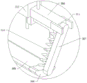
FIG. 1 is a first schematic structural view of an irrigation device for an agricultural planting greenhouse according to the present invention;
FIG. 2 is a schematic structural view II of an irrigation device for an agricultural planting greenhouse according to the present invention;
FIG. 3 is a first cross-sectional view of an irrigation device for an agricultural planting greenhouse according to the present invention;
FIG. 4 is a second cross-sectional view of an irrigation device for an agricultural planting greenhouse according to the present invention;
FIG. 5 is an enlarged view of the portion A in FIG. 1 of the irrigation device for agricultural planting greenhouse according to the present invention;
FIG. 6 is an enlarged view of the portion B in FIG. 1 of the irrigation device for agricultural planting greenhouse according to the present invention;
FIG. 7 is an enlarged view of the portion C in FIG. 3 of the irrigation device for agricultural planting greenhouse in accordance with the present invention;
fig. 8 is an enlarged view of a portion D in fig. 3 of an irrigation device for an agricultural planting greenhouse according to the present invention.
In the figure: 1. a base; 101. a first support leg; 102. a second support leg; 103. placing the plate; 104. a first fixing lever; 105. a second fixing bar; 106. a first lead screw; 107. a locking assembly; 108. a second connecting plate; 109. a second rotating shaft; 110. a first gear; 2. a third gear; 201. a first connecting plate; 202. a first rotating shaft; 203. a toothed plate; 204. a fixed seat; 205. a baffle plate; 206. a first elastic member; 207. a ratchet wheel; 208. a clamping roller assembly; 209. a drive motor; 210. a drive shaft; 3. a belt; 301. a first detachable slide bar; 302. a second detachable slide bar; 303. a second lead screw; 304. a water pump; 305. a water pipe; 306. a second fixing plate; 307. a connecting rod; 308. a top plate; 309. a protection plate; 310. a second elastic member; 311. a limiting plate; 312. a slide plate; 313. a reinforcing plate; 314. a first fixing plate; 315. a second gear; 4. a first support device; 5. and a second support device.
Detailed Description
The technical solutions in the embodiments of the present invention will be clearly and completely described below with reference to the drawings in the embodiments of the present invention, and it is obvious that the described embodiments are only a part of the embodiments of the present invention, and not all of the embodiments.
Example (b):
referring to fig. 1-8, an irrigation device for an agricultural planting greenhouse comprises a first supporting device 4, a second supporting device 5 and a telescopic assembly, wherein the telescopic assembly is connected between the first supporting device 4 and the second supporting device 5, the first supporting device 4 and the second supporting device 5 respectively comprise a base 1, a first supporting leg 101, a second supporting leg 102 and a placing plate 103, the first supporting leg 101 is connected to the top wall of the base 1, the second supporting leg 102 is slidably connected to the inner wall of the first supporting leg 101, the placing plate 103 is fixedly connected to the top wall of the second supporting leg 102, a reinforcing plate 313 is connected between the second supporting leg 102 and the placing plate 103, a first connecting plate 201 and a second connecting plate 108 are connected to the outer wall of the first supporting leg 101, a first rotating shaft 202 is connected to the inner wall of the first connecting plate 201, a lifting device is connected to the outer wall of the first rotating shaft 202, one end of the lifting device, which is far away from the first connecting plate 201, is, the bottom wall of the placing plate 103 is connected with a first fixing plate 314, the inner wall of the first fixing plate 314 is connected with a fixing component, one end of the fixing component, far away from the first fixing plate 314, penetrates through the first supporting device 4 and extends outwards, the outer wall of the fixing component is connected with a sliding plate 312, the outer wall of the sliding plate 312 is connected with a second fixing plate 306, the outer wall of the second fixing plate 306 is connected with a connecting rod 307, the inner wall of one end, far away from the second fixing plate 306, of the connecting rod 307 is connected with a protection component, the output end of the protection component is matched with greenhouse plants, the top wall of the placing plate 103 is connected with a placing seat, the inner wall of the placing seat is connected with a driving motor 209, the output end of the driving motor 209 is connected with a transmission component, one end, far away from the driving motor 209, of the;
the telescopic assembly comprises a first fixing rod 104, a second fixing rod 105 and a first screw 106, the first fixing rod 104 is fixedly connected to the outer wall of the first supporting device 4, the second fixing rod 105 is fixedly connected to the outer wall of the second supporting device 5, one end of the first screw 106 is in threaded connection with the inner wall of the first fixing rod 104, and the end, far away from the first fixing rod 104, of the first screw 106 is in threaded connection with the inner wall of the second fixing rod 105;
the first screw 106 is matched with the first fixing rod 104 through a locking assembly 107;
the lifting device comprises a first transmission assembly and a second transmission assembly, the first transmission assembly comprises a second rotating shaft 109 and a toothed plate 203, the toothed plate 203 is fixedly connected to the outer wall of the second supporting leg 102, one end of the second rotating shaft 109 is rotatably connected to the inner wall of the second connecting plate 108, one end, far away from the second connecting plate 108, of the second rotating shaft 109 is rotatably connected to the inner wall of the first connecting plate 201, the outer wall of the second rotating shaft 109 is connected with a gear assembly, the toothed plate 203 of the output end of the gear assembly is matched, one end of the second transmission assembly is connected to the outer wall of the first connecting plate 201, and one end, far away from the first connecting plate 201, of the second transmission assembly is connected;
the gear assembly comprises a first gear 110, the first gear 110 is fixedly connected to the outer wall of the second rotating shaft 109, and the first gear 110 is meshed with the toothed plate 203;
the second transmission assembly comprises a ratchet wheel 207 and a second gear 315, the ratchet wheel 207 and the second gear 315 are both fixedly connected to the outer wall of the first rotating shaft 202, the outer wall of the second gear 315 is connected with a third gear 2 in a meshed manner, the third gear 2 is fixedly connected to the outer wall of the first rotating shaft 202, the outer wall of the ratchet wheel 207 is connected with a clamping assembly, and the output end of the clamping assembly is connected to the outer wall of the first connecting plate 201;
the clamping assembly comprises a clamping roller assembly 208 and a baffle plate 205, the baffle plate 205 is connected to the outer wall of the first connecting plate 201, the top wall of the baffle plate 205 is connected with a fixed seat 204, the inner wall of the fixed seat 204 is rotatably connected with a hand lever, the clamping roller assembly 208 is connected to the outer wall of the hand lever, and a first elastic piece 206 is connected between the hand lever and the baffle plate 205;
the fixed assembly comprises a first detachable sliding rod 301, a second detachable sliding rod 302 and a second screw rod 303, one end of the first detachable sliding rod 301, one end of the second detachable sliding rod 302 and one end of the second screw rod 303 penetrate through a first fixed plate 314 and extend outwards, and one end of the first detachable sliding rod 301, one end of the second detachable sliding rod 302 and one end of the second screw rod 303 far away from the first fixed plate 314 penetrate through a sliding plate 312 and the first supporting device 4 and extend outwards;
the protection assembly comprises a limiting plate 311 and a top plate 308, the limiting plate 311 is connected to the outer wall of the second fixing plate 306, the top plate 308 is connected to the inner wall of the connecting rod 307, the inner wall of the top plate 308 is connected with a protection plate 309, and a second elastic part 310 is connected between the top plate 308 and the second fixing plate 306;
the conveying assembly comprises a driving shaft 210 and a belt 3, one end of the driving shaft 210 is connected to the inner wall of the output end of the driving motor 209, one end of the belt 3 is connected to the outer wall of the driving motor 209, and the end, far away from the driving motor 209, of the belt 3 is connected to the outer wall of the second screw rod 303;
in the invention, when in use, firstly, the width and the height of the device are adjusted according to the structure of the greenhouse and different crops, then the first screw rod 106 is manually rotated, further the distance between the first fixing rod 104 and the second fixing rod 105 can be changed, further the distance between the first supporting device 4 and the second supporting device 5 in the X-axis direction can be adjusted by arranging the first fixing rod 104, the second fixing rod 105 and the first screw rod 106, thereby the greenhouse with different structures can be used, further the flexibility of the device is improved, then the handle is manually pressed, simultaneously the handle is rotated, further the first rotating shaft 202 is driven to rotate, further the second gear 315 is driven to rotate, further the third gear 2 is driven to rotate, further the first gear 110 is driven to rotate through the second rotating shaft 109, further the second supporting leg 102 is driven to slide along the inner wall of the first supporting leg 101 through the toothed plate 203, further changing the distance between the placing plate 103 and the ground, further adjusting the height of the device in the Y-axis direction by providing the first rotating shaft 202, the second rotating shaft 109, the first gear 110, the second gear 315 and the third gear 2, further adjusting the equipment structure properly according to different crops to enable better irrigation, further improving the flexibility of the device, further adjusting the proper height, further lowering the hand lever, further driving the second elastic member 310 to lock and fix the ratchet wheel 207 through the hand lever driving the clamping roller assembly 208, further avoiding the abnormal problem of sliding of the second supporting leg 102, further ensuring the stability of the operation of the device, then simultaneously starting the driving motor 209 and the water pump 304, further driving the output end of the driving motor 209 to drive the driving shaft 210 to rotate, further driving the belt 3 to rotate along the second lead screw 303, further driving the sliding plate 312 to slide along the outer walls of the first detachable sliding rod 301 and the second detachable sliding rod 302, and then drive connecting rod 307 through second fixed plate 306 and slide, and then drive antiskid ribbed tile 312 and carry out smooth sliding, and then through being provided with guard plate 309, second elastic component 310, connecting rod 307 and slide 312, and then belt 3 and then can fall the plant and make it slope, and then make spun water directly spray on soil and be absorbed by soil, can not be a large amount of attached to on the blade, reduce the evaporation loss, practice thrift the water yield that the single irrigation needs, reach the water conservation purpose.
The above description is only for the preferred embodiment of the present invention, but the scope of the present invention is not limited thereto, and any person skilled in the art should be considered to be within the technical scope of the present invention, and the technical solutions and the inventive concepts thereof according to the present invention should be equivalent or changed within the scope of the present invention.
Claims (10)
1. An irrigation device for an agricultural planting greenhouse, which comprises a first supporting device (4), a second supporting device (5) and a telescopic assembly, wherein the telescopic assembly is connected between the first supporting device (4) and the second supporting device (5), and is characterized in that the first supporting device (4) and the second supporting device (5) both comprise a base (1), a first supporting leg (101), a second supporting leg (102) and a placing plate (103), the first supporting leg (101) is connected to the top wall of the base (1), the second supporting leg (102) is connected to the inner wall of the first supporting leg (101) in a sliding manner, the placing plate (103) is fixedly connected to the top wall of the second supporting leg (102), a reinforcing plate (313) is connected between the second supporting leg (102) and the placing plate (103), a first connecting plate (201) and a second connecting plate (108) are connected to the outer wall of the first supporting leg (101), the inner wall of the first connecting plate (201) is connected with a first rotating shaft (202), the outer wall of the first rotating shaft (202) is connected with a lifting device, one end, far away from the first connecting plate (201), of the lifting device is matched with the second supporting leg (102), the bottom wall of the placing plate (103) is connected with a first fixing plate (314), the inner wall of the first fixing plate (314) is connected with a fixing component, one end, far away from the first fixing plate (314), of the fixing component penetrates through the first supporting device (4) and extends outwards, the outer wall of the fixing component is connected with a sliding plate (312), the outer wall of the sliding plate (312) is connected with a second fixing plate (306), the outer wall of the second fixing plate (306) is connected with a connecting rod (307), the inner wall of one end, far away from the second fixing plate (306), of the connecting rod (307) is connected with a protection component, the improved water-saving device is characterized in that a placing seat is connected to the top wall of the placing plate (103), a driving motor (209) is connected to the inner wall of the placing seat, the output end of the driving motor (209) is connected with a conveying assembly, one end, far away from the driving motor (209), of the conveying assembly is connected to the outer wall of the fixing assembly, a water pump (304) is connected to the top wall of the placing plate (103), the output end of the water pump (304) is connected with a water pipe (305), and one end, far away from the water pump (304), of the water pipe (.
2. The irrigation device for the agricultural planting greenhouse as claimed in claim 1, wherein the telescopic assembly comprises a first fixing rod (104), a second fixing rod (105) and a first screw rod (106), the first fixing rod (104) is fixedly connected to the outer wall of the first supporting device (4), the second fixing rod (105) is fixedly connected to the outer wall of the second supporting device (5), one end of the first screw rod (106) is in threaded connection with the inner wall of the first fixing rod (104), and one end of the first screw rod (106), which is far away from the first fixing rod (104), is in threaded connection with the inner wall of the second fixing rod (105).
3. The irrigation device for the agricultural planting greenhouse of claim 2, wherein the first screw rod (106) and the first fixing rod (104) are matched through a locking assembly (107).
4. The irrigation device for the agricultural planting greenhouse of claim 1, the lifting device comprises a first transmission assembly and a second transmission assembly, the first transmission assembly comprises a second rotating shaft (109) and a toothed plate (203), the toothed plate (203) is fixedly connected to the outer wall of the second support leg (102), one end of the second rotating shaft (109) is rotatably connected to the inner wall of the second connecting plate (108), one end of the second rotating shaft (109) far away from the second connecting plate (108) is rotatably connected to the inner wall of the first connecting plate (201), the outer wall of the second rotating shaft (109) is connected with a gear assembly, the toothed plate (203) of the output end of the gear assembly is matched, one end of the second transmission assembly is connected to the outer wall of the first connecting plate (201), and one end, far away from the first connecting plate (201), of the second transmission assembly is connected to the outer wall of the first supporting leg (101).
5. The irrigation device for the agricultural planting greenhouse as recited in claim 4, wherein the gear assembly comprises a first gear (110), the first gear (110) is fixedly connected to the outer wall of the second rotating shaft (109), and the first gear (110) is in meshed connection with the toothed plate (203).
6. An irrigation device for an agricultural planting greenhouse as claimed in any one of claims 4 to 5, wherein the second transmission assembly comprises a ratchet wheel (207) and a second gear (315), the ratchet wheel (207) and the second gear (315) are both fixedly connected to the outer wall of the first rotating shaft (202), a third gear (2) is engaged and connected to the outer wall of the second gear (315), the third gear (2) is fixedly connected to the outer wall of the first rotating shaft (202), a clamping assembly is connected to the outer wall of the ratchet wheel (207), and the output end of the clamping assembly is connected to the outer wall of the first connecting plate (201).
7. The irrigation device for the agricultural planting greenhouse as claimed in claim 6, wherein the clamping assembly comprises a clamping roller assembly (208) and a baffle (205), the baffle (205) is connected to the outer wall of the first connecting plate (201), a fixed seat (204) is connected to the top wall of the baffle (205), a hand lever is rotatably connected to the inner wall of the fixed seat (204), the clamping roller assembly (208) is connected to the outer wall of the hand lever, and a first elastic member (206) is connected between the hand lever and the baffle (205).
8. The irrigation device for the agricultural planting greenhouse as claimed in claim 1, wherein the fixing assembly comprises a first detachable slide bar (301), a second detachable slide bar (302) and a second screw rod (303), one end of the first detachable slide bar (301), one end of the second detachable slide bar (302) and one end of the second screw rod (303) penetrate through the first fixing plate (314) and extend outwards, and one end of the first detachable slide bar (301), one end of the second detachable slide bar (302) and one end of the second screw rod (303) far away from the first fixing plate (314) penetrate through the sliding plate (312) and the first supporting device (4) and extend outwards.
9. The irrigation device for the agricultural planting greenhouse as claimed in any one of claims 7 to 8, wherein the protection assembly comprises a limiting plate (311) and a top plate (308), the limiting plate (311) is connected to the outer wall of the second fixing plate (306), the top plate (308) is connected to the inner wall of the connecting rod (307), a protection plate (309) is connected to the inner wall of the top plate (308), and a second elastic member (310) is connected between the top plate (308) and the second fixing plate (306).
10. An irrigation device for an agricultural planting greenhouse as claimed in claim 1, wherein the transmission assembly comprises a driving shaft (210) and a belt (3), one end of the driving shaft (210) is connected to the inner wall of the output end of the driving motor (209), one end of the belt (3) is connected to the outer wall of the driving motor (209), and the end, far away from the driving motor (209), of the belt (3) is connected to the outer wall of the second screw rod (303).
Priority Applications (1)
| Application Number | Priority Date | Filing Date | Title |
|---|---|---|---|
| CN202110004762.9A CN112602508B (en) | 2021-01-04 | 2021-01-04 | Irrigation equipment for farming big-arch shelter |
Applications Claiming Priority (1)
| Application Number | Priority Date | Filing Date | Title |
|---|---|---|---|
| CN202110004762.9A CN112602508B (en) | 2021-01-04 | 2021-01-04 | Irrigation equipment for farming big-arch shelter |
Publications (2)
| Publication Number | Publication Date |
|---|---|
| CN112602508A true CN112602508A (en) | 2021-04-06 |
| CN112602508B CN112602508B (en) | 2023-11-21 |
Family
ID=75254739
Family Applications (1)
| Application Number | Title | Priority Date | Filing Date |
|---|---|---|---|
| CN202110004762.9A Active CN112602508B (en) | 2021-01-04 | 2021-01-04 | Irrigation equipment for farming big-arch shelter |
Country Status (1)
| Country | Link |
|---|---|
| CN (1) | CN112602508B (en) |
Cited By (1)
| Publication number | Priority date | Publication date | Assignee | Title |
|---|---|---|---|---|
| CN113785760A (en) * | 2021-09-16 | 2021-12-14 | 山东中建八局投资建设有限公司 | Seedling water supply watering device for afforestation |
Citations (13)
| Publication number | Priority date | Publication date | Assignee | Title |
|---|---|---|---|---|
| CN206104218U (en) * | 2016-10-14 | 2017-04-19 | 重庆七夜科技有限公司 | Support device is irrigate in little sprinkling irrigation that height and width can be adjusted simultaneously |
| CN106577043A (en) * | 2016-12-12 | 2017-04-26 | 无锡市三阳生态农业发展有限公司 | Irrigation device for organic vegetables inside farming greenhouse |
| WO2017143634A1 (en) * | 2016-02-23 | 2017-08-31 | 江苏大学 | Compact irrigation sprinkler mounting device for precise irrigation capable of being disassembled |
| CN207081626U (en) * | 2017-08-24 | 2018-03-09 | 苏州混凝土水泥制品研究院检测中心有限公司 | Elastic modulus of concrete experimental rig |
| RU2017114814A (en) * | 2017-04-26 | 2018-10-26 | Сергей Владимирович Бриндюк | A method of growing seed crops and a device for its implementation (options) |
| CN208224309U (en) * | 2018-02-23 | 2018-12-11 | 广州市英格朗电子科技有限公司 | A kind of high voltage testing device |
| CN209270192U (en) * | 2018-12-04 | 2019-08-20 | 青岛市城阳区人民医院 | A kind of medical treatment and nursing cart |
| CN209503740U (en) * | 2018-12-29 | 2019-10-18 | 上海任道医疗器械有限公司 | A kind of artificial tooth sander |
| JP2019180382A (en) * | 2018-04-08 | 2019-10-24 | 王磊 | Agrochemicals spray vehicle |
| CN110999688A (en) * | 2019-12-31 | 2020-04-14 | 汉寿华诚农业科技有限公司 | Agricultural greenhouse plants and uses water-saving irrigation device |
| CN211259443U (en) * | 2019-11-20 | 2020-08-14 | 天门市江汉三机特车有限责任公司 | Belt stop device of oil pumping unit |
| CN111699890A (en) * | 2020-07-16 | 2020-09-25 | 张玉玲 | Greenhouse vegetable irrigation spraying device |
| CN211793933U (en) * | 2019-12-27 | 2020-10-30 | 姜伟 | Agricultural plant protection spraying apparatus |
-
2021
- 2021-01-04 CN CN202110004762.9A patent/CN112602508B/en active Active
Patent Citations (13)
| Publication number | Priority date | Publication date | Assignee | Title |
|---|---|---|---|---|
| WO2017143634A1 (en) * | 2016-02-23 | 2017-08-31 | 江苏大学 | Compact irrigation sprinkler mounting device for precise irrigation capable of being disassembled |
| CN206104218U (en) * | 2016-10-14 | 2017-04-19 | 重庆七夜科技有限公司 | Support device is irrigate in little sprinkling irrigation that height and width can be adjusted simultaneously |
| CN106577043A (en) * | 2016-12-12 | 2017-04-26 | 无锡市三阳生态农业发展有限公司 | Irrigation device for organic vegetables inside farming greenhouse |
| RU2017114814A (en) * | 2017-04-26 | 2018-10-26 | Сергей Владимирович Бриндюк | A method of growing seed crops and a device for its implementation (options) |
| CN207081626U (en) * | 2017-08-24 | 2018-03-09 | 苏州混凝土水泥制品研究院检测中心有限公司 | Elastic modulus of concrete experimental rig |
| CN208224309U (en) * | 2018-02-23 | 2018-12-11 | 广州市英格朗电子科技有限公司 | A kind of high voltage testing device |
| JP2019180382A (en) * | 2018-04-08 | 2019-10-24 | 王磊 | Agrochemicals spray vehicle |
| CN209270192U (en) * | 2018-12-04 | 2019-08-20 | 青岛市城阳区人民医院 | A kind of medical treatment and nursing cart |
| CN209503740U (en) * | 2018-12-29 | 2019-10-18 | 上海任道医疗器械有限公司 | A kind of artificial tooth sander |
| CN211259443U (en) * | 2019-11-20 | 2020-08-14 | 天门市江汉三机特车有限责任公司 | Belt stop device of oil pumping unit |
| CN211793933U (en) * | 2019-12-27 | 2020-10-30 | 姜伟 | Agricultural plant protection spraying apparatus |
| CN110999688A (en) * | 2019-12-31 | 2020-04-14 | 汉寿华诚农业科技有限公司 | Agricultural greenhouse plants and uses water-saving irrigation device |
| CN111699890A (en) * | 2020-07-16 | 2020-09-25 | 张玉玲 | Greenhouse vegetable irrigation spraying device |
Cited By (1)
| Publication number | Priority date | Publication date | Assignee | Title |
|---|---|---|---|---|
| CN113785760A (en) * | 2021-09-16 | 2021-12-14 | 山东中建八局投资建设有限公司 | Seedling water supply watering device for afforestation |
Also Published As
| Publication number | Publication date |
|---|---|
| CN112602508B (en) | 2023-11-21 |
Similar Documents
| Publication | Publication Date | Title |
|---|---|---|
| CN210094142U (en) | Dragon fruit planting greenhouse | |
| CN211793934U (en) | Novel fruit tree is planted with irrigating spraying device | |
| CN212212052U (en) | Planting frame for agricultural planting | |
| CN216451899U (en) | Afforestation is grown seedlings and is supplied liquid device with intelligence | |
| CN112602508B (en) | Irrigation equipment for farming big-arch shelter | |
| CN214385426U (en) | Irrigation equipment for farming | |
| CN211881525U (en) | Crop planting device | |
| CN219536842U (en) | Landscape design landscape curing means | |
| CN214507990U (en) | Gardens nursery stock water conservation curing means | |
| CN214961076U (en) | Water and fertilizer drip irrigation device for vegetable plantation | |
| CN215073924U (en) | Water and fertilizer integrated drip irrigation device for greenhouse shed | |
| CN212087263U (en) | Vegetable support for agricultural greenhouse | |
| CN112970721A (en) | Walking type farmland pesticide spraying device | |
| CN111543294A (en) | Irrigation device for planting industry | |
| CN218302463U (en) | Environment-friendly movable agronomy device of growing seedlings | |
| CN111149565A (en) | High-efficient planting device is used to farming | |
| CN220755800U (en) | Rolling conveying type melon and vegetable seedling raising bed | |
| CN218889077U (en) | Mushroom planting frame convenient to put | |
| CN217722205U (en) | Plant species plants greenhouse sprinkling irrigation equipment | |
| CN220458063U (en) | Multifunctional planting agricultural greenhouse with monitoring function | |
| CN217184080U (en) | A watering device for vegetable planting big-arch shelter | |
| CN219330054U (en) | Water-saving device for hundred-meter grain water fertilizer irrigation | |
| CN214047257U (en) | Agricultural greenhouse plants and uses pesticide sprinkler | |
| CN216219069U (en) | Novel farming big-arch shelter | |
| CN218649599U (en) | Water-saving irrigation device |
Legal Events
| Date | Code | Title | Description |
|---|---|---|---|
| PB01 | Publication | ||
| PB01 | Publication | ||
| SE01 | Entry into force of request for substantive examination | ||
| SE01 | Entry into force of request for substantive examination | ||
| TA01 | Transfer of patent application right | ||
| TA01 | Transfer of patent application right |
Effective date of registration: 20231026 Address after: No. 85 North Street, Jingdian Town, Neihuang County, Anyang City, Henan Province, 455000 Applicant after: Anyang Hongzhixing Agricultural Technology Co.,Ltd. Address before: 710000 Xi'an University of Architectural Science and Technology, No. 13 Yanta Road, Beilin District, Xi'an City, Shaanxi Province Applicant before: Lei Ming |
|
| GR01 | Patent grant | ||
| GR01 | Patent grant |