CN112524992A - Online cleaning device for condenser - Google Patents
Online cleaning device for condenser Download PDFInfo
- Publication number
- CN112524992A CN112524992A CN202011541439.7A CN202011541439A CN112524992A CN 112524992 A CN112524992 A CN 112524992A CN 202011541439 A CN202011541439 A CN 202011541439A CN 112524992 A CN112524992 A CN 112524992A
- Authority
- CN
- China
- Prior art keywords
- condenser
- cleaning
- storage tank
- liquid storage
- cleaning device
- Prior art date
- Legal status (The legal status is an assumption and is not a legal conclusion. Google has not performed a legal analysis and makes no representation as to the accuracy of the status listed.)
- Granted
Links
Images


Classifications
-
- F—MECHANICAL ENGINEERING; LIGHTING; HEATING; WEAPONS; BLASTING
- F28—HEAT EXCHANGE IN GENERAL
- F28G—CLEANING OF INTERNAL OR EXTERNAL SURFACES OF HEAT-EXCHANGE OR HEAT-TRANSFER CONDUITS, e.g. WATER TUBES OR BOILERS
- F28G13/00—Appliances or processes not covered by groups F28G1/00 - F28G11/00; Combinations of appliances or processes covered by groups F28G1/00 - F28G11/00
-
- F—MECHANICAL ENGINEERING; LIGHTING; HEATING; WEAPONS; BLASTING
- F28—HEAT EXCHANGE IN GENERAL
- F28G—CLEANING OF INTERNAL OR EXTERNAL SURFACES OF HEAT-EXCHANGE OR HEAT-TRANSFER CONDUITS, e.g. WATER TUBES OR BOILERS
- F28G1/00—Non-rotary, e.g. reciprocated, appliances
- F28G1/02—Non-rotary, e.g. reciprocated, appliances having brushes
-
- F—MECHANICAL ENGINEERING; LIGHTING; HEATING; WEAPONS; BLASTING
- F28—HEAT EXCHANGE IN GENERAL
- F28G—CLEANING OF INTERNAL OR EXTERNAL SURFACES OF HEAT-EXCHANGE OR HEAT-TRANSFER CONDUITS, e.g. WATER TUBES OR BOILERS
- F28G15/00—Details
- F28G15/04—Feeding and driving arrangements, e.g. power operation
-
- F—MECHANICAL ENGINEERING; LIGHTING; HEATING; WEAPONS; BLASTING
- F28—HEAT EXCHANGE IN GENERAL
- F28G—CLEANING OF INTERNAL OR EXTERNAL SURFACES OF HEAT-EXCHANGE OR HEAT-TRANSFER CONDUITS, e.g. WATER TUBES OR BOILERS
- F28G9/00—Cleaning by flushing or washing, e.g. with chemical solvents
Abstract
The invention relates to an online cleaning device for a condenser, which comprises a bottom plate, a cleaning device and a rotating device, wherein the cleaning device is arranged on the left side of the upper end of the bottom plate, the rotating device is arranged on the right side of the cleaning device, and the lower end of the rotating device is arranged on the bottom plate. The invention can solve the problems that when the existing equipment is used for cleaning the condenser tube bundle, cleaning agent is generally only injected into the condenser, so that the cleaning effect of the condenser is poor and the cleaning is not uniform, a large amount of scale is adhered to the cleaned condenser tube bundle to influence the subsequent use effect of the condenser, and when the existing equipment is used for cleaning the condenser tube bundle, the condenser tube bundle cannot be rotated generally, so that the contact between the condenser tube bundle and the cleaning agent is insufficient, the cleaning effect of the condenser is influenced, and the like.
Description
Technical Field
The invention relates to the field of condenser cleaning, in particular to an online cleaning device for a condenser.
Background
The condenser is a heat exchanger for condensing the exhaust steam of the steam turbine into water, and is also called a water re-condenser. The condenser is mainly used in a steam turbine power device and is divided into a water-cooling condenser and an air-cooling condenser, and the condenser has the main functions of establishing and maintaining high vacuum at a steam exhaust port of a steam turbine and forming a complete cycle by using water condensed from the steam exhaust of the steam turbine as boiler feed water. And the condenser keeps higher vacuum degree through exchanging heat with circulating water. The safe and economic operation of a power plant unit is seriously influenced by the over-low vacuum of the condenser, and the scaling of a cooling water pipe of the condenser is one of important reasons for the over-low vacuum of the condenser, so that the water pipe after scaling needs to be cleaned regularly.
At present, when cleaning a condenser, the existing equipment generally has the following defects: 1. when the existing equipment is used for cleaning a condenser tube bundle, a cleaning agent is generally only injected into the condenser, so that the cleaning effect of the condenser is poor and the cleaning is uneven, and a large amount of scale is adhered to the cleaned condenser tube bundle, so that the subsequent use effect of the condenser is influenced; 2. when present equipment is wasing the condenser tube bank, can not rotate the condenser tube bank usually, lead to the condenser tube bank not abundant with the contact of cleaner, influence the cleaning performance of condenser.
Disclosure of Invention
Technical problem to be solved
The invention can solve the problems that when the existing equipment is used for cleaning the condenser tube bundle, cleaning agent is generally only injected into the condenser, so that the cleaning effect of the condenser is poor and the cleaning is not uniform, a large amount of scale is adhered to the cleaned condenser tube bundle to influence the subsequent use effect of the condenser, and when the existing equipment is used for cleaning the condenser tube bundle, the condenser tube bundle cannot be rotated generally, so that the contact between the condenser tube bundle and the cleaning agent is insufficient, the cleaning effect of the condenser is influenced, and the like.
(II) technical scheme
In order to achieve the purpose, the invention adopts the following technical scheme that the online cleaning device for the condenser comprises a bottom plate, a cleaning device and a rotating device, wherein the cleaning device is installed on the left side of the upper end of the bottom plate, the rotating device is installed on the right side of the cleaning device, and the lower end of the rotating device is installed on the bottom plate.
The cleaning device comprises a liquid storage tank, a moving mechanism, a support frame, a positioning mechanism and a cleaning mechanism, wherein the liquid storage tank is arranged on a bottom plate, the cross section of the liquid storage tank is of a U-shaped structure, a Fushtaike cleaning agent is filled in the liquid storage tank, the moving mechanism is arranged at the lower end in the liquid storage tank, the support frame is symmetrically arranged at the upper end of the moving mechanism, the middle part of the support frame is of an arc structure, a condenser tube bundle is arranged between the inner parts of the support frames, the positioning mechanisms are symmetrically arranged at the left side and the right side in the liquid storage tank, the inner side of each positioning mechanism is connected with the condenser tube bundle, the positioning mechanism at the right side of the liquid storage tank is connected with a rotating device, the cleaning mechanisms are symmetrically arranged at the front side and the rear side in the liquid, when moving mechanism passes through the support frame and drives the tube bank and carry out reciprocating motion, the Thailand of Fushi contact that the cleaner can be abundant with the tube bank, guarantees that the incrustation scale of adhesion on the tube bank can all be washed clean, and when positioning mechanism drove the rotating device motion, rotating device can rotate on the support frame through positioning mechanism for the tube bank can be abundant with the cleaner contact, improves the effect of condenser tube bank.
Positioning mechanism include linear bearing, guide post, locating plate and clean the unit, the reservoir on install linear bearing, linear bearing is inside to be connected with the guide post through sliding fit's mode, the locating plate is installed to the guide post inboard, evenly install the reference column on the locating plate medial surface, the reference column cooperates with the through-hole joint of condenser tube bank tip, install on the guide post and clean the unit, clean the unit outside and be connected with the reservoir, concrete during operation, the locating plate can press from both sides tightly fixedly with condenser tube bank tip, when the guide post rotates, the guide post can drive the condenser tube bank and rotate, make condenser tube bank hang and can fully contact with the cleaner, clean the unit and can brush the condenser tube bank tip and sweep, guarantee the cleaning performance of tube bank.
Cleaning the unit and including mount, annular frame, clean board, coupling spring, guide bar and expanding spring, the guide post on install the mount through the bearing, the mount inboard is provided with the annular frame, be provided with the ring channel on the annular frame medial surface, install in the ring channel and clean the board, clean and install coupling spring between board and the ring channel, evenly be provided with the brush hair on the board medial surface, the guide bar is evenly installed in the mount outside, the guide bar is connected with the reservoir through sliding fit's mode, be provided with expanding spring on the guide bar, during concrete work, coupling spring drives and cleans the board and hugs closely with condenser tube bank tip all the time, when condenser tube bank rotates, brush hair on cleaning the board and then can brush the tube bank tip, prevent that the incrustation scale from remaining on the tube bank.
As a preferred technical scheme of the invention, the rotating device comprises a connecting frame, a guide frame, a worm and a worm wheel, the connecting frame is mounted on the left side of the upper end of the bottom plate, the section of the connecting frame is of a U-shaped structure, the guide frame is mounted inside the connecting frame, a through groove is formed in the middle of the guide frame, the worm is arranged in the through groove, the worm is connected with the outer side of the positioning mechanism on the right side of the liquid storage tank, a groove is formed in the guide frame, the worm wheel is arranged in the groove and meshed with the worm, the worm wheel is mounted inside the connecting frame through a bearing, when the positioning mechanism reciprocates, the positioning mechanism drives the worm to move, the worm is meshed with the worm wheel to rotate, and then the function of rotating the.
As a preferred technical scheme of the invention, the moving mechanism comprises electric sliders and a moving frame, the electric sliders are symmetrically arranged in the liquid storage tank, the moving frame is symmetrically arranged between the upper ends of the electric sliders, the supporting frame is arranged at the upper end of the moving frame, when the condenser is in specific work, the electric sliders drive the supporting frame to move through the moving frame, and the supporting frame can further drive the condenser tube bundle to reciprocate.
As a preferred technical scheme of the invention, the cleaning mechanism comprises a high-pressure spray pipe, a cleaning plate, a threaded seat and a rotating rod, the high-pressure spray pipe is uniformly arranged at the upper end in the liquid storage tank, the threaded seat is symmetrically arranged on the inner wall of the liquid storage tank, the rotating rod is connected in the threaded seat in a threaded fit mode, the cleaning plate is arranged on the inner side of the rotating rod, bristles are uniformly arranged on the inner concave surface of the cleaning plate, and when the cleaning mechanism works, the high-pressure spray pipe can uniformly spray a Fushitake cleaning agent to the upper end of the tube bundle, so that scale on the tube bundle can be effectively cleaned, the cleaning plate can further clean the outer side of the tube bundle.
As a preferred technical scheme of the invention, the middle part of the support frame is provided with an arc-shaped groove, guide rollers are uniformly arranged in the arc-shaped groove through pin shafts, and the guide rollers can reduce the friction of the condenser tube bundle, so that the condenser tube bundle can rotate in the circumferential direction, and the cleaning and processing of the condenser tube bundle are facilitated.
As a preferred technical scheme of the invention, the annular rubber rings are uniformly arranged on the outer sides of the guide rollers, and the anti-slip threads are uniformly arranged on the outer sides of the rubber rings and can prevent the relative displacement of the condenser tube bundle, so that the condenser tube bundle can only rotate and can be prevented from sliding left and right.
(III) advantageous effects
1. According to the on-line cleaning device for the condenser, the cleaning device can drive the condenser tube bundle to reciprocate, so that the condenser tube bundle can be fully contacted with a cleaning agent, and the condenser tube bundle can generate large impact force with the cleaning agent when moving, and scale adhered to the tube bundle can be effectively washed away;
2. according to the on-line cleaning device for the condenser, the cleaning mechanism can further clean the condenser tube bundle, so that a large amount of scale is prevented from adhering to the cleaned condenser tube bundle, and the subsequent use effect of the condenser is ensured;
3. according to the on-line cleaning device for the condenser, the rotating device can drive the condenser tube bundle to rotate in a reciprocating manner, so that the condenser tube bundle can be fully contacted with a cleaning agent, and the cleaning efficiency of the condenser tube bundle is improved.
Drawings
The invention is further illustrated with reference to the following figures and examples.
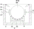
FIG. 1 is a schematic cross-sectional view of the present invention;
FIG. 2 is a schematic cross-sectional view of the reservoir, the moving mechanism, the supporting frame and the cleaning mechanism;
FIG. 3 is a schematic cross-sectional view of the bottom plate, the liquid storage tank, the moving mechanism, the supporting frame and the positioning mechanism;
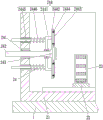
fig. 4 is a schematic sectional view of the guide post and the rotating device according to the present invention.
Detailed Description
The embodiments of the invention will be described in detail below with reference to the drawings, but the invention can be implemented in many different ways as defined and covered by the claims.
As shown in fig. 1 to 4, an online cleaning device for a condenser comprises a bottom plate 1, a cleaning device 2 and a rotating device 3, wherein the cleaning device 2 is installed on the left side of the upper end of the bottom plate 1, the rotating device 3 is installed on the right side of the cleaning device 2, and the lower end of the rotating device 3 is installed on the bottom plate 1.
The cleaning device 2 comprises a liquid storage tank 21, a moving mechanism 22, a support frame 23, a positioning mechanism 24 and a cleaning mechanism 25, wherein the liquid storage tank 21 is arranged on a bottom plate 1, the section of the liquid storage tank 21 is of a U-shaped structure, a Fushtak cleaning agent is filled in the liquid storage tank 21, the moving mechanism 22 is arranged at the lower end in the liquid storage tank 21, the support frame 23 is symmetrically arranged at the upper end of the moving mechanism 22, the middle part of the support frame 23 is of an arc-shaped structure, a condenser tube bundle is arranged between the inner parts of the support frames 23, the positioning mechanisms 24 are symmetrically arranged at the left side and the right side in the liquid storage tank 21, the inner side of each positioning mechanism 24 is connected with the condenser tube bundle, the positioning mechanism 24 positioned at the right side of the liquid storage tank 21 is connected with a rotating device 3, the cleaning mechanisms 25 are symmetrically arranged, positioning mechanism 24 can press from both sides tightly fixedly to condenser tube bank tip, when moving mechanism 22 drives the tube bank through support frame 23 and carries out reciprocating motion, the Thailand of Fushi contacts with the tube bank that the cleaner can be abundant, guarantees that the incrustation scale of adhesion can all be washed clean on the tube bank, when positioning mechanism 24 drives rotating device 3 motion, rotating device 3 can rotate on support frame 23 through positioning mechanism 24 for the tube bank can be fully with the cleaner contact, improves the effect of condenser tube bank.
The moving mechanism 22 comprises an electric slider 221 and a moving frame 222, the electric slider 221 is symmetrically installed inside the liquid storage tank 21, the moving frame 222 is symmetrically installed between the upper ends of the electric sliders 221, the support frame 23 is installed at the upper end of the moving frame 222, during specific work, the electric slider 221 drives the support frame 23 to move through the moving frame 222, and the support frame 23 can further drive the condenser tube bundle to reciprocate.
The guide roll outside evenly install annular rubber circle, the rubber circle outside evenly is provided with anti-skidding line, relative displacement can be avoided taking place to the condenser tube bank by anti-skidding line for the condenser tube bank only can rotate, avoids taking place the horizontal slip.
The positioning mechanism 24 comprises a linear bearing 241, a guide post 242, a positioning plate 243 and a cleaning unit 244, the liquid storage tank 21 is provided with a linear bearing 241, the interior of the linear bearing 241 is connected with a guide post 242 in a sliding fit mode, the inner side of the guide post 242 is provided with a positioning plate 243, the inner side surface of the positioning plate 243 is uniformly provided with positioning posts which are in clamping fit with through holes at the end part of the condenser tube bundle, the guide post 242 is provided with a cleaning unit 244, the outer side of the cleaning unit 244 is connected with the liquid storage tank 21, and during the specific work, the positioning plate 243 can be clamped and fixed with the end part of the condenser tube bundle, when the guide posts 242 rotate, the guide posts 242 can drive the condenser tube bundle to rotate, make condenser tube bank hang can fully contact with the cleaner, clean unit 244 and can brush the condenser tube bank tip and sweep, guarantee the cleaning performance of tube bank.
The cleaning unit 244 comprises a fixed frame 2441, an annular frame 2442, a cleaning plate 2443, a connecting spring 2444, a guide rod 2445 and a telescopic spring 2446, a fixed frame 2441 is arranged on the guide post 242 through a bearing, an annular frame 2442 is arranged on the inner side of the fixed frame 2441, an annular groove is arranged on the inner side surface of the annular frame 2442, a cleaning plate 2443 is arranged in the annular groove, a connecting spring 2444 is arranged between the cleaning plate 2443 and the annular groove, bristles are uniformly arranged on the inner side surface of the cleaning plate 2443, a guide rod 2445 is uniformly arranged on the outer side of the fixed frame 2441, the guide rod 2445 is connected with the liquid storage tank 21 in a sliding fit manner, a telescopic spring 2446 is arranged on the guide rod 2445, when the device works specifically, the connecting spring 2444 drives the cleaning plate 2443 to be always tightly attached to the end part of the condenser pipe bundle, when the condenser tube bundle rotates, the brush hair on the cleaning plate 2443 can brush the end part of the tube bundle, and scale is prevented from remaining on the tube bundle.
The invention comprises the following steps in specific work:
the first step is as follows: manually hoisting the condenser tube bundle to be cleaned to the interior of the liquid storage tank 21, supporting the condenser tube bundle by using a supporting frame 23, and clamping and fixing the end part of the condenser tube bundle by using a positioning mechanism 24;
the second step is that: starting the electric sliding block 221, driving the support frame 23 to move by the electric sliding block 221 through the moving frame 222, and driving the condenser tube bundle to reciprocate by the support frame 23;
the third step: when condenser tube bank carries out reciprocating motion, condenser tube bank passes through positioning mechanism 24 and drives 3 movements of rotating device, and rotating device 3 then can drive condenser tube bank reciprocating motion for condenser tube bank can be abundant contact with the inside fushitaike cleaner of reservoir 21, clean unit 244 can be further brush the condenser tube bank tip and sweep, wiper mechanism 25 can be further brush the outside condenser tube bank, guarantee condenser tube bank's cleaning performance.
The above description is only a preferred embodiment of the present invention and is not intended to limit the present invention, and various modifications and changes may be made by those skilled in the art. Any modification, equivalent replacement, or improvement made within the spirit and principle of the present invention should be included in the protection scope of the present invention.
Claims (6)
1. The utility model provides a condenser on-line cleaning device, includes bottom plate (1), belt cleaning device (2) and rotating device (3), its characterized in that: bottom plate (1) upper end left side install belt cleaning device (2), belt cleaning device (2) right side is installed and is rotated device (3), is installed on bottom plate (1) rotating device (3) lower extreme, wherein:
the cleaning device (2) comprises a liquid storage tank (21), a moving mechanism (22), a supporting frame (23), a positioning mechanism (24) and a cleaning mechanism (25), the device is characterized in that the liquid storage tank (21) is installed on the bottom plate (1), the section of the liquid storage tank (21) is of a U-shaped structure, a Fushtaike cleaning agent is filled in the liquid storage tank (21), a moving mechanism (22) is installed at the lower end in the liquid storage tank (21), supporting frames (23) are symmetrically installed at the upper end of the moving mechanism (22), the middle of each supporting frame (23) is of an arc-shaped structure, condenser tube bundles are placed between the insides of the supporting frames (23), positioning mechanisms (24) are symmetrically installed on the left side and the right side of the inside of the liquid storage tank (21), the inner sides of the positioning mechanisms (24) are connected with the condenser tube bundles, the positioning mechanisms (24) on the right side of the liquid storage tank;
the positioning mechanism (24) comprises a linear bearing (241), a guide post (242), a positioning plate (243) and a cleaning unit (244), the linear bearing (241) is installed on the liquid storage tank (21), the guide post (242) is connected inside the linear bearing (241) in a sliding fit mode, the positioning plate (243) is installed on the inner side of the guide post (242), the positioning post is evenly installed on the inner side of the positioning plate (243), the positioning post is in clamping fit with a through hole in the end part of the condenser tube bundle, the cleaning unit (244) is installed on the guide post (242), and the outer side of the cleaning unit (244) is connected with the liquid storage tank (21);
cleaning unit (244) including mount (2441), annular frame (2442), clean board (2443), coupling spring (2444), guide bar (2445) and expanding spring (2446), guide post (242) on install mount (2441) through the bearing, mount (2441) inboard is provided with annular frame (2442), be provided with the ring channel on annular frame (2442) medial surface, install in the ring channel and clean board (2443), install coupling spring (2444) between clean board (2443) and the ring channel, evenly be provided with the brush hair on clean board (2443) medial surface, evenly install guide bar (2445) outside mount (2441), guide bar (2445) are connected with reservoir (21) through sliding fit's mode, are provided with expanding spring (2446) on guide bar (2445).
2. The online cleaning device for the condenser according to claim 1, characterized in that: rotating device (3) including link (31), leading truck (32), worm (33) and worm wheel (34), bottom plate (1) upper end left side install link (31), link (31) cross-section is U type structure, link (31) are inside to be installed leading truck (32), leading truck (32) middle part is provided with logical groove, logical inslot is provided with worm (33), positioning mechanism (24) outside on worm (33) and reservoir (21) right side is connected, leading truck (32) are provided with the recess, be provided with worm wheel (34) in the recess, worm wheel (34) mesh with worm (33), worm wheel (34) are installed inside link (31) through the bearing.
3. The online cleaning device for the condenser according to claim 1, characterized in that: the moving mechanism (22) comprises an electric sliding block (221) and a moving frame (222), the electric sliding block (221) is symmetrically installed inside the liquid storage tank (21), the moving frame (222) is symmetrically installed between the upper ends of the electric sliding block (221), and the supporting frame (23) is installed at the upper end of the moving frame (222).
4. The online cleaning device for the condenser according to claim 1, characterized in that: cleaning mechanism (25) including high-pressure spray pipe (251), clean board (252), screw seat (253) and dwang (254), inside upper end of reservoir (21) evenly install high-pressure spray pipe (251), screw seat (253) are installed to symmetry on reservoir (21) inner wall, screw seat (253) are inside to be connected with dwang (254) through screw-thread fit's mode, clean board (252) are installed to dwang (254) inboard, clean evenly be provided with the brush hair on board (252) the interior concave surface.
5. The online cleaning device for the condenser according to claim 1, characterized in that: the middle part of the support frame (23) is provided with an arc-shaped groove, and guide rollers are uniformly arranged in the arc-shaped groove through pin shafts.
6. The online cleaning device for the condenser according to claim 5, characterized in that: the guide roll outside evenly install annular rubber circle, the rubber circle outside evenly is provided with anti-skidding line.
Priority Applications (1)
| Application Number | Priority Date | Filing Date | Title |
|---|---|---|---|
| CN202011541439.7A CN112524992B (en) | 2020-12-23 | 2020-12-23 | Online cleaning device for condenser |
Applications Claiming Priority (1)
| Application Number | Priority Date | Filing Date | Title |
|---|---|---|---|
| CN202011541439.7A CN112524992B (en) | 2020-12-23 | 2020-12-23 | Online cleaning device for condenser |
Publications (2)
| Publication Number | Publication Date |
|---|---|
| CN112524992A true CN112524992A (en) | 2021-03-19 |
| CN112524992B CN112524992B (en) | 2021-07-30 |
Family
ID=74975941
Family Applications (1)
| Application Number | Title | Priority Date | Filing Date |
|---|---|---|---|
| CN202011541439.7A Active CN112524992B (en) | 2020-12-23 | 2020-12-23 | Online cleaning device for condenser |
Country Status (1)
| Country | Link |
|---|---|
| CN (1) | CN112524992B (en) |
Cited By (2)
| Publication number | Priority date | Publication date | Assignee | Title |
|---|---|---|---|---|
| CN113551554A (en) * | 2021-07-27 | 2021-10-26 | 王永刚 | Automatic cleaning device for air cooling island radiating fins |
| CN113586194A (en) * | 2021-09-14 | 2021-11-02 | 安阳钢铁股份有限公司 | Ring cooling waste heat power generation device and method for steel plant |
Citations (7)
| Publication number | Priority date | Publication date | Assignee | Title |
|---|---|---|---|---|
| GB1222862A (en) * | 1968-07-10 | 1971-02-17 | Flexible Drives Gilman S Ltd | Rotary pipe-cleaning toolhead |
| CN106288937A (en) * | 2015-05-27 | 2017-01-04 | 陈来福 | A kind of plant condenser on-line auto-cleaning robot |
| US20170321975A1 (en) * | 2016-05-03 | 2017-11-09 | Peinemann Equipment B.V. | Method and apparatus for cleaning tubes in a rotary path |
| CN107702587A (en) * | 2017-10-30 | 2018-02-16 | 俞天翔 | Couple spiral cleaning formula natural-circulation evaporator |
| CN109201661A (en) * | 2018-09-12 | 2019-01-15 | 詹哲品 | A kind of pipeline automatic pollutant removal cleaning equipment and pipeline automatic processing method |
| CN210486654U (en) * | 2019-08-16 | 2020-05-08 | 山西中科德昂信息科技有限公司 | Descaling device for power plant condenser |
| CN211903910U (en) * | 2020-04-21 | 2020-11-10 | 北京建企动力科技工程有限公司 | Heating radiator cleaning device for heating ventilation |
-
2020
- 2020-12-23 CN CN202011541439.7A patent/CN112524992B/en active Active
Patent Citations (7)
| Publication number | Priority date | Publication date | Assignee | Title |
|---|---|---|---|---|
| GB1222862A (en) * | 1968-07-10 | 1971-02-17 | Flexible Drives Gilman S Ltd | Rotary pipe-cleaning toolhead |
| CN106288937A (en) * | 2015-05-27 | 2017-01-04 | 陈来福 | A kind of plant condenser on-line auto-cleaning robot |
| US20170321975A1 (en) * | 2016-05-03 | 2017-11-09 | Peinemann Equipment B.V. | Method and apparatus for cleaning tubes in a rotary path |
| CN107702587A (en) * | 2017-10-30 | 2018-02-16 | 俞天翔 | Couple spiral cleaning formula natural-circulation evaporator |
| CN109201661A (en) * | 2018-09-12 | 2019-01-15 | 詹哲品 | A kind of pipeline automatic pollutant removal cleaning equipment and pipeline automatic processing method |
| CN210486654U (en) * | 2019-08-16 | 2020-05-08 | 山西中科德昂信息科技有限公司 | Descaling device for power plant condenser |
| CN211903910U (en) * | 2020-04-21 | 2020-11-10 | 北京建企动力科技工程有限公司 | Heating radiator cleaning device for heating ventilation |
Cited By (3)
| Publication number | Priority date | Publication date | Assignee | Title |
|---|---|---|---|---|
| CN113551554A (en) * | 2021-07-27 | 2021-10-26 | 王永刚 | Automatic cleaning device for air cooling island radiating fins |
| CN113586194A (en) * | 2021-09-14 | 2021-11-02 | 安阳钢铁股份有限公司 | Ring cooling waste heat power generation device and method for steel plant |
| CN113586194B (en) * | 2021-09-14 | 2022-11-22 | 安阳钢铁股份有限公司 | Ring cooling waste heat power generation device and method for steel plant |
Also Published As
| Publication number | Publication date |
|---|---|
| CN112524992B (en) | 2021-07-30 |
Similar Documents
| Publication | Publication Date | Title |
|---|---|---|
| CN112524992B (en) | Online cleaning device for condenser | |
| CN201702123U (en) | Combination cleaning device of screen printing plate | |
| CN211209648U (en) | Photovoltaic board cleaning device | |
| CN112264360A (en) | Outer wall belt cleaning device is retrieved with old and useless electric wire to electric power engineering | |
| CN208290738U (en) | A kind of spray head cleaning device of ink-jet printer | |
| CN214344900U (en) | Cleaning device for sediment incrustation on back surface of filter cloth of drying machine | |
| CN113058916B (en) | Precise automobile part remanufacturing pretreatment method | |
| CN207736973U (en) | A kind of environmentally protective printing equipment nozzle cleaning and wiping ink device | |
| CN111136068A (en) | Steel pipe cleaning equipment for machining | |
| CN214638872U (en) | Rotary lifting brushing mechanism | |
| CN216757503U (en) | Comprehensive dirt cleaning device for machining pipe shaft parts | |
| CN213501432U (en) | Printing roller processing and cleaning equipment | |
| CN213067158U (en) | Cooling tower cleaning device with water circulation function | |
| CN114061363A (en) | Heat exchanger heat pipe cleaning equipment | |
| CN209938029U (en) | Environment-friendly printing machine convenient to change brush roll | |
| CN219947645U (en) | Printing plate cleaning device | |
| CN220479570U (en) | Belt cleaning device for hydraulic equipment | |
| CN214719091U (en) | Petrochemical pipeline belt cleaning device | |
| CN219360662U (en) | Cleaning mechanism for conduction band | |
| CN214767187U (en) | Fan coil cleaning device | |
| CN218873163U (en) | High-pressure cleaning machine for inner and outer walls of quartz tube | |
| CN211515331U (en) | Weaving rubber roll belt cleaning device | |
| CN220611422U (en) | Scrubbing device of cup sealing machine | |
| CN219523393U (en) | Cleaning device for cylinder printing equipment | |
| CN218692646U (en) | Double-end water tank wire drawing machine |
Legal Events
| Date | Code | Title | Description |
|---|---|---|---|
| PB01 | Publication | ||
| PB01 | Publication | ||
| SE01 | Entry into force of request for substantive examination | ||
| SE01 | Entry into force of request for substantive examination | ||
| GR01 | Patent grant | ||
| GR01 | Patent grant | ||
| PE01 | Entry into force of the registration of the contract for pledge of patent right |
Denomination of invention: An on-line cleaning device for condenser Effective date of registration: 20211223 Granted publication date: 20210730 Pledgee: Linyi Huitong Cleaning Co.,Ltd. Pledgor: Shandong Jinnuo Power Technology Co.,Ltd. Registration number: Y2021980015925 |
|
| PE01 | Entry into force of the registration of the contract for pledge of patent right |