CN112497049A - Grinding device for high-temperature quick-opening spherical sealing cut-off valve - Google Patents
Grinding device for high-temperature quick-opening spherical sealing cut-off valve Download PDFInfo
- Publication number
- CN112497049A CN112497049A CN202011336523.5A CN202011336523A CN112497049A CN 112497049 A CN112497049 A CN 112497049A CN 202011336523 A CN202011336523 A CN 202011336523A CN 112497049 A CN112497049 A CN 112497049A
- Authority
- CN
- China
- Prior art keywords
- grinding
- belt pulley
- output shaft
- connecting axle
- work piece
- Prior art date
- Legal status (The legal status is an assumption and is not a legal conclusion. Google has not performed a legal analysis and makes no representation as to the accuracy of the status listed.)
- Pending
Links
Images


Classifications
-
- B—PERFORMING OPERATIONS; TRANSPORTING
- B24—GRINDING; POLISHING
- B24B—MACHINES, DEVICES, OR PROCESSES FOR GRINDING OR POLISHING; DRESSING OR CONDITIONING OF ABRADING SURFACES; FEEDING OF GRINDING, POLISHING, OR LAPPING AGENTS
- B24B37/00—Lapping machines or devices; Accessories
- B24B37/04—Lapping machines or devices; Accessories designed for working plane surfaces
- B24B37/07—Lapping machines or devices; Accessories designed for working plane surfaces characterised by the movement of the work or lapping tool
- B24B37/08—Lapping machines or devices; Accessories designed for working plane surfaces characterised by the movement of the work or lapping tool for double side lapping
-
- B—PERFORMING OPERATIONS; TRANSPORTING
- B24—GRINDING; POLISHING
- B24B—MACHINES, DEVICES, OR PROCESSES FOR GRINDING OR POLISHING; DRESSING OR CONDITIONING OF ABRADING SURFACES; FEEDING OF GRINDING, POLISHING, OR LAPPING AGENTS
- B24B37/00—Lapping machines or devices; Accessories
- B24B37/11—Lapping tools
- B24B37/12—Lapping plates for working plane surfaces
-
- B—PERFORMING OPERATIONS; TRANSPORTING
- B24—GRINDING; POLISHING
- B24B—MACHINES, DEVICES, OR PROCESSES FOR GRINDING OR POLISHING; DRESSING OR CONDITIONING OF ABRADING SURFACES; FEEDING OF GRINDING, POLISHING, OR LAPPING AGENTS
- B24B37/00—Lapping machines or devices; Accessories
- B24B37/34—Accessories
-
- B—PERFORMING OPERATIONS; TRANSPORTING
- B24—GRINDING; POLISHING
- B24B—MACHINES, DEVICES, OR PROCESSES FOR GRINDING OR POLISHING; DRESSING OR CONDITIONING OF ABRADING SURFACES; FEEDING OF GRINDING, POLISHING, OR LAPPING AGENTS
- B24B41/00—Component parts such as frames, beds, carriages, headstocks
- B24B41/04—Headstocks; Working-spindles; Features relating thereto
-
- B—PERFORMING OPERATIONS; TRANSPORTING
- B24—GRINDING; POLISHING
- B24B—MACHINES, DEVICES, OR PROCESSES FOR GRINDING OR POLISHING; DRESSING OR CONDITIONING OF ABRADING SURFACES; FEEDING OF GRINDING, POLISHING, OR LAPPING AGENTS
- B24B47/00—Drives or gearings; Equipment therefor
- B24B47/10—Drives or gearings; Equipment therefor for rotating or reciprocating working-spindles carrying grinding wheels or workpieces
- B24B47/12—Drives or gearings; Equipment therefor for rotating or reciprocating working-spindles carrying grinding wheels or workpieces by mechanical gearing or electric power
Abstract
The invention discloses a grinding device of a high-temperature quick-opening spherical sealing cut-off valve, which relates to the field of grinding equipment and comprises a base frame, a driving device, an angle iron frame and a moving seat, wherein the angle iron frame and the moving seat are jointly installed on the base frame, a workpiece to be ground and a plurality of grinding heads which are arranged oppositely up and down are installed on the moving seat, the grinding heads and the workpiece to be ground are respectively and rotatably installed on the moving seat, and the output end of the driving device is respectively connected with the workpiece to be ground and the grinding heads and drives the grinding heads to synchronously grind when the workpiece to be ground rotates. The invention has the advantages of high grinding precision and high efficiency and quality guarantee.
Description
Technical Field
The invention relates to the field of grinding equipment, in particular to a grinding device for a high-temperature quick-opening spherical sealing cut-off valve.
Background
The upper and lower planes of the valve rod of the ultrafast-opening high-temperature cut-off valve and the valve clack of the valve clack assembly are sealing surfaces, the parallelism of the two planes is required to be 0.02, the surface roughness reaches Ra0.02 (mirror surface), and coarse and fine grinding and polishing are required to be carried out. The existing grinding equipment cannot adapt to the grinding processing of the product.
Disclosure of Invention
In order to overcome the defects of the background art, the invention provides the grinding device of the high-temperature quick-opening spherical sealing cut-off valve, which has high grinding precision and high efficiency and quality guarantee.
The technical scheme adopted by the invention is as follows: the utility model provides a high temperature is fast opens grinding device of spherical seal shut-off valve, its includes base frame, drive arrangement and installs the angle iron frame on the base frame jointly and removes the seat, remove and install the grinding head that is waited to grind work piece and a plurality of relative setting from top to bottom on the seat, the grinding head with wait to grind work piece respectively rotatable install remove on the seat, drive arrangement's output is connected respectively wait to grind work piece and grinding head, and drive the grinding head is waited to grind the work piece and is ground when rotating in step.
The driving device comprises a motor arranged on the front face of the angle iron frame and a speed reducer arranged on the back face of the angle iron frame, wherein the speed reducer is provided with a first output shaft extending upwards, a second output shaft extending downwards and an input shaft in transmission connection with the motor.
The grinding head comprises a grinding shaft and a grinding disc arranged at one end of the grinding shaft, a fixed sleeve is rotatably arranged on the outer circumference of the grinding shaft, an adjusting nut and an elastic piece are sleeved on the grinding shaft, and the elastic piece is abutted and arranged between the adjusting nut and the grinding disc.
A first belt pulley is fixedly installed on the first output shaft, a fourth belt pulley and a fifth belt pulley are fixedly installed on the second output shaft, a second belt pulley is installed at the other end of the grinding shaft, a third belt pulley is installed at one end of the workpiece to be ground, and the first belt pulley and the fifth belt pulley are respectively in belt transmission with the second belt pulley; the fourth belt pulley and the third belt pulley are driven by a belt.
The utility model discloses a quick-witted angle iron frame, including first output shaft, last connecting axle, angle iron frame, first belt pulley, last adapter sleeve and last connecting axle of fixed connection are overlapped to the cover on the first output shaft, be equipped with the confession on the angle iron frame go up the last fixing base that the connecting axle passed, go up the outer circumference cover of connecting axle and be equipped with the sleeve pipe, sleeve pipe and last fixing base fixed connection and with last connecting axle between adopt normal running fit, first belt pulley passes through the parallel.
The grinding machine is characterized in that a workpiece connecting sleeve connected through a flat key is sleeved on the workpiece to be ground, a third belt pulley is fixedly sleeved on the workpiece connecting sleeve, and a workpiece bearing seat which is in running fit with the workpiece connecting sleeve and is fixedly connected with a movable seat is sleeved at the lower end of the workpiece connecting sleeve.
The fourth belt pulley passes through the flat key suit at second output shaft tip, the tip of second output shaft still overlaps the lower connecting axle with fourth belt pulley fixed connection, the fifth belt pulley passes through the flat key and installs the lower extreme of lower connecting axle, the outer circumference of lower connecting axle is installed running fit and with angle iron frame fixed connection's step.
Remove the seat including removing base, upper cover plate and the two stand of fixed connection, be equipped with adjustment mechanism between base frame and the removal base, adjustment mechanism includes:
the fixed block is fixedly arranged on the side surface of the base frame;
the adjusting plate is fixedly arranged on the side wall of the movable base;
the adjusting screw is installed on the fixed block in a threaded mode and extends out of two side faces of the fixed block;
one end of the adjusting screw rod is used for manual operation, and the other end of the adjusting screw rod is in running fit with the adjusting plate.
The base frame upper surface is equipped with the distribution and a plurality of screw and the installation uide pin in the screw of both sides, remove the seat both sides and respectively have a plurality of microscler guiding holes that supply the uide pin mobile location.
The invention has the beneficial effects that: according to the technical scheme, the workpiece to be ground is rotated through the driving device, the upper plane and the lower plane of the workpiece to be ground are simultaneously and automatically rotated by the grinding disc to simultaneously grind the sealing surface, so that the efficiency is high, and the quality can be ensured; the whole set of device is provided with only one motor, the upper output shaft and the lower output shaft of the speed reducer are driven to rotate, and the output shafts drive the workpiece to be ground and the upper grinding head and the lower grinding head to rotate respectively through belt transmission.
Drawings
Fig. 1 is a schematic structural diagram of a grinding device for a high-temperature quick-opening spherical sealing shut-off valve according to an embodiment of the present invention.
Fig. 2 is a schematic back view of a grinding device for a high-temperature quick-opening spherical sealing shut-off valve.
Fig. 3 is a schematic structural view of the movable base.
Fig. 4 is a schematic structural diagram of the adjustment mechanism.
Fig. 5 is a schematic structural diagram of the first output shaft.
Fig. 6 is a cross-sectional view of the first output shaft.
Fig. 7 is a schematic view of the mounting structure of the workpiece to be ground.
Fig. 8 is a schematic sectional view showing the installation of a workpiece to be ground.
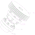
FIG. 9 is a schematic view of a polishing head.
FIG. 10 is a cross-sectional view of the polishing head.
Fig. 11 is a schematic structural diagram of the second output shaft.
Fig. 12 is a cross-sectional view of the second output shaft.
Figure 13 is a schematic structural view of the base frame.
Detailed Description
The embodiments of the invention will be further described with reference to the accompanying drawings in which:
as shown in the figure, the grinding device of the high-temperature quick-opening spherical sealing cut-off valve comprises a base frame 1, a driving device 2, an angle iron frame 3 and a moving seat 4 which are jointly installed on the base frame 1, wherein a workpiece 5 to be ground and a plurality of grinding heads 6 which are arranged oppositely up and down are installed on the moving seat 4, the grinding heads 6 and the workpiece 5 to be ground are respectively and rotatably installed on the moving seat 4, the output end of the driving device 2 is respectively connected with the workpiece 5 to be ground and the grinding heads 6, and the grinding heads 6 are driven to synchronously grind when the workpiece 5 to be ground rotates; the whole set of device is provided with only one motor, the upper output shaft and the lower output shaft of the speed reducer are driven to rotate, and the output shafts drive the workpiece to be ground and the upper grinding head and the lower grinding head to rotate respectively through belt transmission.
The driving device 2 comprises a motor 21 arranged on the front surface of the angle iron frame 3 and a speed reducer 22 arranged on the back surface of the angle iron frame 3, wherein the speed reducer 22 is provided with a first output shaft 23 extending upwards, a second output shaft 24 extending downwards and an input shaft 25 in transmission connection with the motor 21.
The workpiece to be ground is an assembly of a valve rod and a valve clack which are fixedly connected, and the valve rod is coaxially arranged on the upper side and the lower side of the valve clack respectively; the upper and lower both sides face of valve clack needs to be ground by the grinding head and is processed, and the motor in this embodiment drives the speed reducer and rotates, and first output shaft drives the grinding head that is located the valve clack top and rotates, and the second output shaft drives the grinding head that is located the valve clack below and rotates, and the work piece that waits to grind simultaneously also drives and takes place to rotate, and the efficiency of processing and grinding quality can both be guaranteed.
The grinding head 6 comprises a grinding shaft 61, a grinding disc 62 arranged at one end of the grinding shaft 61, and a fixing sleeve 63 rotatably arranged on the outer circumference of the grinding shaft 61, wherein an adjusting nut 64 and an elastic piece 65 are sleeved on the grinding shaft 61, and the elastic piece 65 is arranged between the adjusting nut 64 and the grinding disc 62 in a butting manner.
In addition, the grinding shaft in the embodiment is provided with an inner hole for inserting the cylindrical end part of the grinding disc, the cylindrical end part is connected with the grinding shaft through a pin shaft after being inserted, and the pin shaft is installed and matched with a large gap, so that the floating installation of the grinding disc is formed. The elastic piece adopts a compression spring.
A first belt pulley 26 is fixedly installed on the first output shaft 23, a fourth belt pulley 27 and a fifth belt pulley 28 are fixedly installed on the second output shaft 24, a second belt pulley 66 is installed at the other end of the grinding shaft 61, a third belt pulley 51 is installed at one end of the workpiece 5 to be ground, and the first belt pulley 26 and the fifth belt pulley 28 are respectively in belt transmission with the second belt pulley 66; the fourth pulley 27 and the third pulley 51 are driven by a belt.
The cover is equipped with fixed connection's last adapter sleeve 231 and last connecting axle 232 on the first output shaft 23, be equipped with the confession on the angle iron frame 3 go up last fixing base 234 that connecting axle 232 passed, go up the outer circumference cover of connecting axle 232 and be equipped with sleeve pipe 235, sleeve pipe 235 with last fixing base 234 fixed connection and last connecting axle 232 between adopt normal running fit, first belt pulley 26 is installed in the upper end of last connecting axle 232 through the parallel key, makes things convenient for the dismouting to change, has also improved installation stability simultaneously.
A workpiece connecting sleeve 52 connected through a flat key is sleeved on the workpiece 5 to be ground, a fixing sleeve 63 of the third belt pulley 51 is arranged on the workpiece connecting sleeve 52, and a workpiece bearing seat 53 which is in running fit with the workpiece connecting sleeve 52 and is fixedly connected with the movable seat 4 is sleeved at the lower end of the workpiece connecting sleeve 52; make things convenient for the dismouting to change, also improved installation stability simultaneously.
The fourth belt pulley 27 is sleeved at the end of the second output shaft 24 through a flat key, the end of the second output shaft 24 is further sleeved with a lower connecting shaft 271 fixedly connected with the fourth belt pulley 27, the fifth belt pulley 28 is installed at the lower end of the lower connecting shaft 271 through a flat key, and a lower bearing seat 272 which is in running fit with the outer circumference of the lower connecting shaft 271 and is fixedly connected with the angle iron frame 3 is installed on the outer circumference of the lower connecting shaft 271; make things convenient for the dismouting to change, also improved installation stability simultaneously. .
Remove seat 4 including removing base 41, upper cover plate 42 and the stand 43 of the two of fixed connection, be equipped with adjustment mechanism 7 between base frame 1 and the removal base 41, adjustment mechanism 7 includes:
a fixed block 71 fixedly installed at a side surface of the base frame 1;
an adjusting plate 72 fixedly installed at a sidewall of the moving base 41;
an adjusting screw 73 which is threadedly mounted on the fixed block 71 and extends out from both side surfaces of the fixed block 71;
adjusting screw 73 one end supplies manually operation, and the other end with adjusting plate 72 normal running fit through adjusting screw pulling removal base, the elasticity of adjustable belt.
The upper surface of the base frame 1 is provided with a plurality of screw holes 11 distributed on two sides, guide pins are arranged in the screw holes 11, and a plurality of long guide holes 44 for the guide pins to move and position are respectively arranged on two sides of the movable base 4.
In the description of the present invention, it should be noted that the terms "center", "longitudinal", "lateral", "up", "down", "front", "back", "left", "right", "vertical", "horizontal", "top", "bottom", "inner", "outer", etc., indicate orientations or positional relationships based on those shown in the drawings, and are only for convenience of description and simplicity of description, but do not indicate or imply that the referred device or element must have a specific orientation, be constructed and operated in a specific orientation, and thus, should not be construed as limiting the present invention. Furthermore, the terms "first" and "second" are used for descriptive purposes only and are not to be construed as indicating or implying relative importance.
In the description of the present invention, it should be noted that, unless otherwise explicitly specified or limited, the terms "mounted," "connected," and "connected" are to be construed broadly, e.g., as meaning either a fixed connection, a removable connection, or an integral connection; can be mechanically or electrically connected; they may be connected directly or indirectly through intervening media, or they may be interconnected between two elements. The specific meanings of the above terms in the present invention can be understood in specific cases to those skilled in the art. In addition, in the description of the present invention, "a plurality" means two or more unless otherwise specified.
The skilled person should understand that: although the invention has been described in terms of the above specific embodiments, the inventive concept is not limited thereto and any modification applying the inventive concept is intended to be included within the scope of the patent claims.
Claims (9)
1. The utility model provides a high temperature is quick to open grinder of sealed cut-off valve of sphere which characterized in that: it includes base frame (1), drive arrangement (2) and installs angle iron frame (3) and removal seat (4) on base frame (1) jointly, remove and install grinding head (6) that relative setting about waiting to grind work piece (5) and a plurality of on seat (4), grinding head (6) and waiting to grind work piece (5) rotatable the installing respectively on removing seat (4), the output of drive arrangement (2) is connected respectively wait to grind work piece (5) and grinding head (6), and drives grinding head (6) grind when waiting to grind work piece (5) and rotate in step.
2. The grinding device for the high-temperature quick-opening spherical sealing shut-off valve according to claim 1, characterized in that: the driving device (2) comprises a motor (21) arranged on the front surface of the angle iron frame (3) and a speed reducer (22) arranged on the back surface of the angle iron frame (3), wherein the speed reducer (22) is provided with a first output shaft (23) extending upwards, a second output shaft (24) extending downwards and an input shaft (25) in transmission connection with the motor (21).
3. The grinding device for the high-temperature quick-opening spherical sealing shut-off valve according to claim 2, characterized in that: grinding head (6) are including grinding axle (61), float and install grinding disk (62) at grinding axle (61) one end, rotate and install fixed cover (63) of grinding axle (61) outer circumference, the cover is equipped with adjusting nut (64) and elastic component (65) on grinding axle (61), elastic component (65) are contradicted and are installed between adjusting nut (64) and grinding disk (62).
4. The grinding device for the high-temperature quick-opening spherical sealing shut-off valve according to claim 3, characterized in that: a first belt pulley (26) is fixedly mounted on the first output shaft (23), a fourth belt pulley (27) and a fifth belt pulley (28) are fixedly mounted on the second output shaft (24), a second belt pulley (66) is mounted at the other end of the grinding shaft (61), a third belt pulley (51) is mounted at one end of the workpiece (5) to be ground, and the first belt pulley (26) and the fifth belt pulley (28) are in belt transmission with the second belt pulley (66) respectively; the fourth belt pulley (27) and the third belt pulley (51) are driven by a belt.
5. The grinding device for the high-temperature quick-opening spherical sealing shut-off valve according to claim 1, characterized in that: the utility model discloses a connecting axle, including first output shaft (23), first output shaft (23) go up the cover and be equipped with fixed connection's last adapter sleeve (231) and last connecting axle (232), be equipped with the confession on angle iron frame (3) go up last fixing base (234) that connecting axle (232) passed, go up the outer circumference cover of connecting axle (232) and be equipped with sleeve pipe (235), adopt normal running fit between sleeve pipe (235) and last fixing base (234) fixed connection and last connecting axle (232), first belt pulley (26) are installed in the upper end of last connecting axle (232) through the parallel key.
6. The grinding device for the high-temperature quick-opening spherical sealing shut-off valve according to claim 1, characterized in that: treat to grind work piece (5) and go up the cover and be equipped with work piece adapter sleeve (52) through the parallel key connection, the fixed cover (63) of third belt pulley (51) is adorned on work piece adapter sleeve (52), the pot head is equipped with rather than normal running fit and with work piece bearing frame (53) that remove seat (4) fixed connection under work piece adapter sleeve (52).
7. The grinding device for the high-temperature quick-opening spherical sealing shut-off valve according to claim 1, characterized in that: fourth belt pulley (27) pass through the flat key suit at second output shaft (24) tip, the tip of second output shaft (24) still overlaps and is equipped with lower connecting axle (271) with fourth belt pulley (27) fixed connection, fifth belt pulley (28) are installed through the flat key the lower extreme of lower connecting axle (271), the lower bearing frame (272) that normal running fit and with angle iron frame (3) fixed connection are installed to the outer circumference of lower connecting axle (271).
8. The grinding device for the high-temperature quick-opening spherical sealing shut-off valve according to claim 1, characterized in that: remove seat (4) including removing stand (43) of base (41), upper cover plate (42) and fixed connection the two, be equipped with adjustment mechanism (7) between base frame (1) and removal base (41), adjustment mechanism (7) include:
a fixed block (71) fixedly mounted on a side surface of the base frame (1);
an adjusting plate (72) fixedly mounted on a side wall of the moving base (41);
the adjusting screw rod (73) is installed on the fixed block (71) in a threaded mode and extends out of two side faces of the fixed block (71);
one end of the adjusting screw rod (73) is used for manual operation, and the other end of the adjusting screw rod is in running fit with the adjusting plate (72).
9. The apparatus for grinding a high temperature quick opening spherical sealing shut-off valve according to claim 8, wherein: the base frame (1) upper surface is equipped with a plurality of screw (11) and the installation uide pin in screw (11) of distribution and both sides, remove seat (4) both sides and respectively have a plurality of microscler guiding holes (44) that supply the uide pin removal location.
Priority Applications (2)
| Application Number | Priority Date | Filing Date | Title |
|---|---|---|---|
| CN202011336523.5A CN112497049A (en) | 2020-11-25 | 2020-11-25 | Grinding device for high-temperature quick-opening spherical sealing cut-off valve |
| PCT/CN2020/136378 WO2022110340A1 (en) | 2020-11-25 | 2020-12-15 | Grinding device for high-temperature fast-opening spherical sealing shut-off valve |
Applications Claiming Priority (1)
| Application Number | Priority Date | Filing Date | Title |
|---|---|---|---|
| CN202011336523.5A CN112497049A (en) | 2020-11-25 | 2020-11-25 | Grinding device for high-temperature quick-opening spherical sealing cut-off valve |
Publications (1)
| Publication Number | Publication Date |
|---|---|
| CN112497049A true CN112497049A (en) | 2021-03-16 |
Family
ID=74958527
Family Applications (1)
| Application Number | Title | Priority Date | Filing Date |
|---|---|---|---|
| CN202011336523.5A Pending CN112497049A (en) | 2020-11-25 | 2020-11-25 | Grinding device for high-temperature quick-opening spherical sealing cut-off valve |
Country Status (2)
| Country | Link |
|---|---|
| CN (1) | CN112497049A (en) |
| WO (1) | WO2022110340A1 (en) |
Citations (11)
| Publication number | Priority date | Publication date | Assignee | Title |
|---|---|---|---|---|
| CN2843743Y (en) * | 2005-10-12 | 2006-12-06 | 廖敌江 | Four main cone double-ended grinding machine |
| KR20070029403A (en) * | 2005-09-09 | 2007-03-14 | 강창원 | An apparatus for polishing decoration frame of mobile phone |
| CN202103527U (en) * | 2011-06-16 | 2012-01-04 | 成都大宏立机器制造有限公司 | Mounting device for motor of jaw breaker |
| CN102049726B (en) * | 2010-07-14 | 2012-05-30 | 中国石油天然气股份有限公司 | Device for grinding valve clack of safety valve |
| CN102626890A (en) * | 2012-04-24 | 2012-08-08 | 安徽合一电气科技有限公司 | Two-sided automatic polishing machine |
| CN102627188A (en) * | 2012-03-31 | 2012-08-08 | 江苏新蕾麦芽有限公司 | Tensioning adjustment device for conveying belt in malt conveyer |
| CN104441069A (en) * | 2014-11-21 | 2015-03-25 | 张家界福安家木业有限公司 | Old material idler wheel type feeding cement-removing log sawing machine |
| CN208945885U (en) * | 2018-09-30 | 2019-06-07 | 东莞市智昕自动化仪表有限公司 | A kind of Pneumatic butterfly valve processing inner ring burnishing device |
| CN208961652U (en) * | 2018-11-06 | 2019-06-11 | 韶关市立全机械有限公司 | A kind of compressor valve plate grinding device |
| CN210413982U (en) * | 2019-07-04 | 2020-04-28 | 南京固华机电科技有限公司 | Double-head floor type high-speed grinding machine |
| CN111168542A (en) * | 2020-01-19 | 2020-05-19 | 中海石油东营石化有限公司 | Valve burnishing device for sewage treatment convenient to adjust |
Family Cites Families (6)
| Publication number | Priority date | Publication date | Assignee | Title |
|---|---|---|---|---|
| JPS6190872A (en) * | 1984-07-03 | 1986-05-09 | Showa Zoki Kk | Original position keeping unit of spring rear face grinding wheel in spring grinding machine |
| DE102012203617A1 (en) * | 2012-03-07 | 2013-09-12 | Wafios Ag | Spring end grinding machine with several loading plates |
| CN102785142B (en) * | 2012-08-17 | 2014-09-24 | 湖南为百科技有限责任公司 | Double-shaft single-surface grinding polishing all-in-one machine for lens |
| CN204308740U (en) * | 2014-12-15 | 2015-05-06 | 河南盛誉实业有限公司 | A kind of semisphere valve grinder |
| CN204800391U (en) * | 2015-07-21 | 2015-11-25 | 首钢京唐钢铁联合有限责任公司 | Circle shear cutting edge coping device |
| CN206550819U (en) * | 2017-03-08 | 2017-10-13 | 浙江东特金属科技有限公司 | Rubbing head for stainless steel plate mirror finish |
-
2020
- 2020-11-25 CN CN202011336523.5A patent/CN112497049A/en active Pending
- 2020-12-15 WO PCT/CN2020/136378 patent/WO2022110340A1/en active Application Filing
Patent Citations (11)
| Publication number | Priority date | Publication date | Assignee | Title |
|---|---|---|---|---|
| KR20070029403A (en) * | 2005-09-09 | 2007-03-14 | 강창원 | An apparatus for polishing decoration frame of mobile phone |
| CN2843743Y (en) * | 2005-10-12 | 2006-12-06 | 廖敌江 | Four main cone double-ended grinding machine |
| CN102049726B (en) * | 2010-07-14 | 2012-05-30 | 中国石油天然气股份有限公司 | Device for grinding valve clack of safety valve |
| CN202103527U (en) * | 2011-06-16 | 2012-01-04 | 成都大宏立机器制造有限公司 | Mounting device for motor of jaw breaker |
| CN102627188A (en) * | 2012-03-31 | 2012-08-08 | 江苏新蕾麦芽有限公司 | Tensioning adjustment device for conveying belt in malt conveyer |
| CN102626890A (en) * | 2012-04-24 | 2012-08-08 | 安徽合一电气科技有限公司 | Two-sided automatic polishing machine |
| CN104441069A (en) * | 2014-11-21 | 2015-03-25 | 张家界福安家木业有限公司 | Old material idler wheel type feeding cement-removing log sawing machine |
| CN208945885U (en) * | 2018-09-30 | 2019-06-07 | 东莞市智昕自动化仪表有限公司 | A kind of Pneumatic butterfly valve processing inner ring burnishing device |
| CN208961652U (en) * | 2018-11-06 | 2019-06-11 | 韶关市立全机械有限公司 | A kind of compressor valve plate grinding device |
| CN210413982U (en) * | 2019-07-04 | 2020-04-28 | 南京固华机电科技有限公司 | Double-head floor type high-speed grinding machine |
| CN111168542A (en) * | 2020-01-19 | 2020-05-19 | 中海石油东营石化有限公司 | Valve burnishing device for sewage treatment convenient to adjust |
Non-Patent Citations (1)
| Title |
|---|
| 谢伟东: "《研磨技术问答》", 30 April 1982, 哈尔滨:黑龙江科学技术出版社 * |
Also Published As
| Publication number | Publication date |
|---|---|
| WO2022110340A1 (en) | 2022-06-02 |
Similar Documents
| Publication | Publication Date | Title |
|---|---|---|
| CN112247256B (en) | Aluminum profile machining system | |
| CN205415216U (en) | Automatic polish mechanism | |
| CN109848832A (en) | Hub vibrational grinder | |
| CN114324044B (en) | Intelligent cloth wear resistance detection device and use method | |
| CN103158059B (en) | Wafer grinding equipment | |
| CN112497049A (en) | Grinding device for high-temperature quick-opening spherical sealing cut-off valve | |
| CN110712078B (en) | Blade chamfering machine | |
| CN214559002U (en) | Automatic heavy grinding device of valve body | |
| CN206536322U (en) | The sanding apparatus at right angle in a kind of tank | |
| CN202910689U (en) | Belt sander | |
| CN205325366U (en) | Silicon wafer stick chamfering apparatus | |
| CN205496716U (en) | Multistation hydraulic pressure tapping machine | |
| CN205363478U (en) | Optical lens piece multistation grinding device | |
| CN212471008U (en) | Connector shell polishing equipment | |
| CN212170076U (en) | Double-station vertical and horizontal shaft diamond grinding wheel in-place dresser | |
| CN209811920U (en) | Device for polishing and removing burrs on arc edge of machined product | |
| CN206839829U (en) | A kind of grinder | |
| CN211332634U (en) | Quick-change grinding wheel device and grinding machine thereof | |
| CN219561666U (en) | Numerical control gear grinding machine with tool grinding device | |
| CN219853724U (en) | Stainless steel ball grinder | |
| CN211491054U (en) | Heater is polished and is used positioner | |
| CN219816083U (en) | Sanding, dispersing and stirring multipurpose machine | |
| CN212496899U (en) | Adapter sleeve lock nut grinding device | |
| CN220680449U (en) | Constant force polishing head | |
| CN214869697U (en) | Full sphere three-axis precision grinding equipment for large-diameter sphere |
Legal Events
| Date | Code | Title | Description |
|---|---|---|---|
| PB01 | Publication | ||
| PB01 | Publication | ||
| SE01 | Entry into force of request for substantive examination | ||
| SE01 | Entry into force of request for substantive examination | ||
| RJ01 | Rejection of invention patent application after publication | ||
| RJ01 | Rejection of invention patent application after publication |
Application publication date: 20210316 |