CN112441120A - Installing support and car of installation double fork arm suspension bumper shock absorber and last control arm - Google Patents
Installing support and car of installation double fork arm suspension bumper shock absorber and last control arm Download PDFInfo
- Publication number
- CN112441120A CN112441120A CN201910812760.5A CN201910812760A CN112441120A CN 112441120 A CN112441120 A CN 112441120A CN 201910812760 A CN201910812760 A CN 201910812760A CN 112441120 A CN112441120 A CN 112441120A
- Authority
- CN
- China
- Prior art keywords
- control arm
- plate
- mounting
- shock absorber
- upper control
- Prior art date
- Legal status (The legal status is an assumption and is not a legal conclusion. Google has not performed a legal analysis and makes no representation as to the accuracy of the status listed.)
- Pending
Links
- 239000006096 absorbing agent Substances 0.000 title claims abstract description 26
- 230000035939 shock Effects 0.000 title claims abstract description 26
- 239000000725 suspension Substances 0.000 title claims abstract description 23
- 238000009434 installation Methods 0.000 title claims description 8
- 230000009977 dual effect Effects 0.000 claims description 6
- 230000002093 peripheral effect Effects 0.000 abstract description 6
- 238000000034 method Methods 0.000 abstract description 5
- 230000000694 effects Effects 0.000 abstract description 4
- 230000009286 beneficial effect Effects 0.000 abstract description 2
- 238000003754 machining Methods 0.000 abstract 1
- 229910000838 Al alloy Inorganic materials 0.000 description 6
- 238000013461 design Methods 0.000 description 3
- 238000011161 development Methods 0.000 description 3
- 238000011160 research Methods 0.000 description 3
- 238000003466 welding Methods 0.000 description 3
- 238000005516 engineering process Methods 0.000 description 2
- 238000012545 processing Methods 0.000 description 2
- 238000009825 accumulation Methods 0.000 description 1
- XAGFODPZIPBFFR-UHFFFAOYSA-N aluminium Chemical compound [Al] XAGFODPZIPBFFR-UHFFFAOYSA-N 0.000 description 1
- 229910052782 aluminium Inorganic materials 0.000 description 1
- 238000005266 casting Methods 0.000 description 1
- 230000007547 defect Effects 0.000 description 1
- 238000012986 modification Methods 0.000 description 1
- 230000004048 modification Effects 0.000 description 1
- 230000003014 reinforcing effect Effects 0.000 description 1
- 238000007493 shaping process Methods 0.000 description 1
Images


Classifications
-
- B—PERFORMING OPERATIONS; TRANSPORTING
- B62—LAND VEHICLES FOR TRAVELLING OTHERWISE THAN ON RAILS
- B62D—MOTOR VEHICLES; TRAILERS
- B62D21/00—Understructures, i.e. chassis frame on which a vehicle body may be mounted
- B62D21/11—Understructures, i.e. chassis frame on which a vehicle body may be mounted with resilient means for suspension, e.g. of wheels or engine; sub-frames for mounting engine or suspensions
-
- B—PERFORMING OPERATIONS; TRANSPORTING
- B60—VEHICLES IN GENERAL
- B60G—VEHICLE SUSPENSION ARRANGEMENTS
- B60G13/00—Resilient suspensions characterised by arrangement, location or type of vibration dampers
- B60G13/001—Arrangements for attachment of dampers
- B60G13/003—Arrangements for attachment of dampers characterised by the mounting on the vehicle body or chassis of the damper unit
-
- B—PERFORMING OPERATIONS; TRANSPORTING
- B60—VEHICLES IN GENERAL
- B60G—VEHICLE SUSPENSION ARRANGEMENTS
- B60G7/00—Pivoted suspension arms; Accessories thereof
- B60G7/008—Attaching arms to unsprung part of vehicle
Abstract
The invention discloses a mounting bracket for mounting a double-fork arm suspension shock absorber and an upper control arm and an automobile, which comprises an upper cover plate and a boss arranged on the upper surface of the upper cover plate, wherein the bottom of the boss is provided with a mounting space matched with a mounting seat on the shock absorber, and the boss is also provided with a threaded hole; the upper cover plate is fixedly provided with a front wall plate, an inner wall plate, a rear wall plate and an outer wall plate which are connected in pairs in sequence, the outer side surface of the front wall plate is fixedly provided with a front apron, the outer side surface of the rear wall plate is fixedly provided with a rear apron, and the front apron and the rear apron are provided with locking components for locking the upper control arm. The invention has the following beneficial effects: the upper control arm is installed through the containing cavities arranged on the two sides of the installing support, the shock absorber is installed on the boss of the upper cover plate, the peripheral size of the installing support is reduced to the maximum extent, the effects of reducing weight and releasing arrangement space of other parts are achieved, ribs in the cavity are removed, and the machining and forming process is greatly simplified.
Description
Technical Field
The invention relates to the technical field of automobiles, in particular to a mounting bracket for mounting a double-fork arm suspension shock absorber and an upper control arm and an automobile.
Background
The rapid development of new energy automobiles, particularly the limitation of the existing automobile battery technology on the endurance mileage of electric automobiles, puts higher and higher requirements on the light weight design of the automobiles. Therefore, the research and application of the aluminum alloy frame are greatly emphasized, and the aluminum alloy frame with lighter weight is applied to new energy automobiles, particularly electric automobiles, and becomes an industry development trend for increasing the endurance mileage. The tendency of the domestic automobile industry to develop towards the high end is more and more obvious after years of accumulation and rapid development, so that the double-fork-arm suspension with better performance than the conventional Macpherson suspension is more and more applied in China, and particularly on the front-edge research of new energy automobiles, the front suspension is basically of a double-fork-arm structure.
In the front-edge research of new energy automobiles, particularly electric automobiles, the automobiles mostly adopt a double-fork-arm front suspension aluminum alloy frame structure. In the industry today, the mainstream installation scheme of the double-wishbone suspension shock absorber and the upper control arm on the aluminum alloy frame is as follows: the shock absorber and the upper control arm are connected to a mounting seat, the mounting seat is made into a large half-box thin-wall aluminum casting, the shock absorber and the upper control arm are covered below, and the middle part of the upper end surface of the mounting seat is bulged upwards to form a shock absorber mounting surface for mounting the shock absorber; ribs are respectively arranged on two sides of the inner cavity of the mounting seat and used for mounting an upper control arm; the lower end of the mounting seat is connected to the inner side of the front longitudinal beam in a welding mode. This solution is equipped with the following drawbacks: the seat has large peripheral size and large mass, and occupies too much arrangement space of other parts; the inner cavity ribs are provided with the upper control arms, and the processing and the forming are troublesome; the mounting seat is welded on the inner side of the longitudinal beam, when the suspension is impacted by vertical load, the moment applied to the mounting seat through the shock absorber is large, the connection is unreliable, and a transverse reinforcing rod is mostly required to be mounted on the upper end face of the mounting seat to reinforce the transverse supporting rigidity of the mounting seat; the mounting seat is connected with the longitudinal beam through an aluminum alloy welding process, and the process is complex.
Disclosure of Invention
The invention aims to overcome the defects in the prior art and provides a mounting bracket for mounting a double-fork-arm suspension shock absorber and an upper control arm and an automobile.
The purpose of the invention is realized by the following technical scheme:
a mounting bracket for mounting a double-fork-arm suspension shock absorber and an upper control arm comprises an upper cover plate and a boss arranged on the upper surface of the upper cover plate, wherein a mounting space matched with a mounting seat on the shock absorber is arranged at the bottom of the boss, and a threaded hole corresponding to the mounting seat is also formed in the boss; the lower surface of the upper cover plate is fixedly provided with a front wall plate, an inner wall plate, a rear wall plate and an outer wall plate which are connected in pairs in sequence, the outer side surface of the front wall plate is fixedly provided with a front wall skirt which forms a front containing cavity of a front lining of the upper control arm, the outer side surface of the rear wall plate is fixedly provided with a rear skirt which forms a rear containing cavity of a rear lining of the upper control arm, and the front skirt and the rear skirt are provided with locking components for locking the upper control arm.
Preferably, the locking assembly at least comprises a first bolt hole arranged on the front apron and a second bolt hole arranged on the front wall plate and corresponding to the first bolt hole; the rear apron is characterized by further comprising a third bolt hole formed in the rear apron and a fourth bolt hole formed in the rear apron and corresponding to the third bolt hole.
Preferably, the front apron and the rear apron are both in a half-box shape.
Preferably, the boss is cylindrical, a through hole is formed on the central axis of the boss, and a flange is arranged on the boundary of the through hole.
Preferably, a rib plate extends from each of the front wall plate and the rear wall plate, the bottom surface of the rib plate is fixedly connected with the upper surface of the supporting plate, the inner side surface of the supporting plate is fixedly connected with the inner wall plate, and the supporting plate is provided with a mounting hole connected with the longitudinal beam.
Preferably, the bottom of the inner enclosing plate is also provided with a connecting hole connected with the longitudinal beam.
An automobile comprising a mounting bracket as described above for mounting a dual wishbone suspension damper and an upper control arm.
The invention has the following beneficial effects: the design is exquisite, and the control arm installation will be gone up through the holding cavity that sets up in this installing support both sides, and the bumper shock absorber is installed on the boss of upper cover plate, reduces the peripheral size of installing support in the at utmost, reaches the effect that falls heavy and release other spare parts and arrange the space, has got rid of the rib in the cavity moreover, very big simplification machine-shaping technology. Meanwhile, the mounting bracket is connected with the longitudinal beam through the connecting hole, so that the moment applied to the mounting bracket by the shock absorber when the suspension is subjected to vertical impact force is reduced. The mounting holes are also designed on the upper surfaces of the supporting plates and the longitudinal beams, so that the connection reliability and the transverse rigidity can be greatly improved.
Drawings
The technical scheme of the invention is further explained by combining the accompanying drawings as follows:
FIG. 1: a perspective view of the invention in a first direction;
FIG. 2: a perspective view of the present invention in a second orientation, wherein the stringers and dampers are removed;
FIG. 3: a perspective view of the present invention in a third orientation, wherein the stringers and dampers are removed.
Detailed Description
The present invention will be described in detail below with reference to specific embodiments shown in the drawings. These embodiments are not intended to limit the present invention, and structural, methodical, or functional changes that may be made by one of ordinary skill in the art in light of these embodiments are intended to be within the scope of the present invention.
The present invention is not limited to the above embodiments, and structural, methodological, or functional changes made by those skilled in the art according to the embodiments are included in the scope of the present invention.
In the description of the present invention, it is to be understood that the terms "center", "longitudinal", "lateral", "up", "down", "front", "back", "left", "right", "vertical", "horizontal", "top", "bottom", "inner", "outer", and the like, indicate orientations or positional relationships based on those shown in the drawings, and are used only for convenience in describing the present invention and for simplicity in description, and do not indicate or imply that the referenced devices or elements must have a particular orientation, be constructed and operated in a particular orientation, and thus, are not to be construed as limiting the present invention. Furthermore, the terms "first", "second", etc. are used for descriptive purposes only and are not to be construed as indicating or implying relative importance or implicitly indicating the number of technical features indicated. Thus, a feature defined as "first," "second," etc. may explicitly or implicitly include one or more of that feature. In the description of the present invention, "a plurality" means two or more unless otherwise specified.
In the description of the present invention, it should be noted that, unless otherwise explicitly specified or limited, the terms "mounted," "connected," and "connected" are to be construed broadly, e.g., as meaning either a fixed connection, a removable connection, or an integral connection; can be mechanically or electrically connected; they may be connected directly or indirectly through intervening media, or they may be interconnected between two elements. The specific meaning of the above terms in the present invention can be understood by those of ordinary skill in the art through specific situations.
The present invention will be described in detail below with reference to the embodiments with reference to the attached drawings.
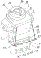
As shown in fig. 1 to 3, the present invention discloses a mounting bracket for mounting a double-wishbone suspension shock absorber and an upper control arm, comprising an upper cover plate 1 and a boss 2 arranged on the upper surface of the upper cover plate 1, wherein the bottom of the boss 2 is provided with a mounting space matched with a mounting seat on the shock absorber 100, and the boss 2 is further provided with threaded holes 21, 22, 23 corresponding to the mounting seat. Of course, other numbers of threaded holes 23 may be provided, and may be adjusted accordingly according to actual requirements. The shock absorber is arranged inside the boss 2, so that the peripheral size of the mounting bracket can be reduced to the greatest extent, and the effects of reducing weight and releasing arrangement space of other parts are achieved.
In this embodiment, the boss 2 is cylindrical, wherein a through hole 24 is formed on the axis, and a flange 25 is formed on the boundary of the through hole 24. This design can be used to dodge the bellying in mount pad middle part on the bumper shock absorber, simultaneously, flange 25 sets up can strengthen the peripheral structural strength of through-hole 24 prevents its fracture, prolongs its life.
In the invention, a front enclosing plate 3, an inner enclosing plate 4, a rear enclosing plate 5 and an outer enclosing plate 6 which are connected in pairs in sequence are fixedly arranged on the lower surface of the upper cover plate 1, a front enclosing skirt 7 forming a front accommodating cavity 31 of an upper control arm front bushing (not shown in the figure) is fixedly arranged on the outer side surface of the front enclosing plate 3, a rear enclosing skirt 8 forming a rear accommodating cavity 51 of an upper control arm rear bushing (not shown in the figure) is fixedly arranged on the outer side surface of the rear enclosing plate 5, and the front enclosing skirt 7 and the rear enclosing skirt 8 are in a half box shape. The front accommodating cavity 31 and the rear accommodating cavity 51 are respectively used for accommodating the upper control arm front bushing and the upper control arm rear bushing, so that the peripheral size of the mounting bracket can be reduced to the greatest extent, and the effects of reducing weight and releasing arrangement space of other parts are achieved. The upper control arm front bushing and the upper control arm rear bushing are locked in the corresponding front accommodating cavity 31 and the corresponding rear accommodating cavity 51 by the locking assembly.
Specifically, the locking assembly includes at least a first bolt hole 71 provided in the front skirt 7 and a second bolt hole 32 provided in the dash panel 3 corresponding to the first bolt hole 71. The rear apron also comprises a third bolt hole 81 arranged on the rear apron 8 and a fourth bolt hole 52 arranged on the rear apron 5 and corresponding to the third bolt hole 81. Of course, other locking structures may be adopted, which are within the protection scope of the present invention and are not limited specifically.
A rib plate 41 extends from each of the front wall plate 3 and the rear wall plate 5, the bottom surface of the rib plate 41 is fixedly connected with the upper surface of the support plate 9, the inner side surface of the support plate is fixedly connected with the inner wall plate 4, and the support plate 9 is provided with mounting holes 91, 92 and 93 connected with the longitudinal beam 200. Compared with the prior art, the rib in the cavity is removed, and the rib plate is placed on the outer side of the mounting bracket, so that the processing and forming process can be greatly simplified. Furthermore, the bottom of the inside boarding 4 is provided with connecting holes 42, 43, 44, 45, 46 and 47 connected with the longitudinal beam 200. The connecting holes 42, 43, 44, 45, 46 and 47 are connected with the longitudinal beam by adopting rivets to penetrate through the connecting holes, so that the complex aluminum alloy welding process is avoided, the cost is reduced, and the wide applicability is realized.
The invention also discloses an automobile which comprises the mounting bracket for mounting the double-fork-arm suspension shock absorber and the upper control arm.
It should be understood that although the present description refers to embodiments, not every embodiment contains only a single technical solution, and such description is for clarity only, and those skilled in the art should make the description as a whole, and the technical solutions in the embodiments can also be combined appropriately to form other embodiments understood by those skilled in the art.
The above-listed detailed description is only a specific description of a possible embodiment of the present invention, and they are not intended to limit the scope of the present invention, and equivalent embodiments or modifications made without departing from the technical spirit of the present invention should be included in the scope of the present invention.
Claims (7)
1. The installing support of installation double fork arm suspension bumper shock absorber and last control arm, its characterized in that: the shock absorber comprises an upper cover plate (1) and a boss (2) arranged on the upper surface of the upper cover plate (1), wherein the bottom of the boss (2) is provided with an installation space matched with an installation seat on the shock absorber (100), and the boss (2) is also provided with threaded holes (21, 22 and 23) corresponding to the installation seat; the lower surface of the upper cover plate (1) is fixedly provided with a front enclosing plate (3), an inner enclosing plate (4), a rear enclosing plate (5) and an outer enclosing plate (6) which are connected in pairs in sequence, the outer side surface of the front enclosing plate (3) is fixedly provided with a front enclosing plate (7) which forms a front containing cavity (31) of an upper control arm front bushing, the outer side surface of the rear enclosing plate (5) is fixedly provided with a rear enclosing plate (8) which forms a rear containing cavity (51) of an upper control arm rear bushing, and the front enclosing plate (7) and the rear enclosing plate (8) are provided with locking components for locking the upper control arm.
2. The mounting bracket for mounting a dual wishbone suspension damper and an upper control arm of claim 1 wherein: the locking assembly at least comprises a first bolt hole (71) arranged on the front apron (7) and a second bolt hole (32) arranged on the front wall plate (3) and corresponding to the first bolt hole (71); the rear apron is characterized by further comprising a third bolt hole (81) formed in the rear apron (8) and a fourth bolt hole (52) formed in the rear apron (5) and corresponding to the third bolt hole (81).
3. The mounting bracket for mounting a dual wishbone suspension damper and an upper control arm of claim 1 wherein: the front apron (7) and the rear apron (8) are both in a half-box shape.
4. The mounting bracket for mounting a dual wishbone suspension damper and an upper control arm of claim 1 wherein: the boss (2) is cylindrical, a through hole (24) is formed in the central axis of the boss, and a flange (25) is arranged on the boundary of the through hole (24).
5. The mounting bracket for mounting a dual wishbone suspension damper and an upper control arm of claim 1 wherein: a rib plate (41) extends out of the front wall plate (3) and the rear wall plate (5), the bottom surface of the rib plate (41) is fixedly connected with the upper surface of the supporting plate (9), the inner side surface of the supporting plate (9) is fixedly connected with the inner wall plate (4), and mounting holes (91, 92 and 93) connected with the longitudinal beam (200) are formed in the supporting plate (9).
6. The mounting bracket for mounting a dual wishbone suspension damper and an upper control arm of claim 5, wherein: and connecting holes (42, 43, 44, 45, 46 and 47) connected with the longitudinal beam (200) are further formed in the bottom of the inner coaming (4).
7. An automobile, characterized in that: a mounting bracket for mounting a double wishbone suspension shock absorber and an upper control arm according to any one of claims 1 to 6.
Priority Applications (1)
| Application Number | Priority Date | Filing Date | Title |
|---|---|---|---|
| CN201910812760.5A CN112441120A (en) | 2019-08-30 | 2019-08-30 | Installing support and car of installation double fork arm suspension bumper shock absorber and last control arm |
Applications Claiming Priority (1)
| Application Number | Priority Date | Filing Date | Title |
|---|---|---|---|
| CN201910812760.5A CN112441120A (en) | 2019-08-30 | 2019-08-30 | Installing support and car of installation double fork arm suspension bumper shock absorber and last control arm |
Publications (1)
| Publication Number | Publication Date |
|---|---|
| CN112441120A true CN112441120A (en) | 2021-03-05 |
Family
ID=74740922
Family Applications (1)
| Application Number | Title | Priority Date | Filing Date |
|---|---|---|---|
| CN201910812760.5A Pending CN112441120A (en) | 2019-08-30 | 2019-08-30 | Installing support and car of installation double fork arm suspension bumper shock absorber and last control arm |
Country Status (1)
| Country | Link |
|---|---|
| CN (1) | CN112441120A (en) |
Citations (10)
| Publication number | Priority date | Publication date | Assignee | Title |
|---|---|---|---|---|
| US5538274A (en) * | 1993-04-14 | 1996-07-23 | Oshkosh Truck Corporation | Modular Independent coil spring suspension |
| KR20070032594A (en) * | 2005-09-16 | 2007-03-22 | 현대자동차주식회사 | Suspension System For Vehicle |
| CN102107677A (en) * | 2009-12-23 | 2011-06-29 | 中国第一汽车集团公司 | Upper control arm support assembly |
| KR20140042563A (en) * | 2012-09-28 | 2014-04-07 | 롯데케미칼 주식회사 | Mounting bracket for suspension of automotive |
| CN206953923U (en) * | 2017-07-12 | 2018-02-02 | 安徽吉美新能源汽车有限公司 | New-energy automobile front suspension tower |
| CN108275210A (en) * | 2018-02-11 | 2018-07-13 | 安徽江淮汽车集团股份有限公司 | A kind of damper tower structure assembly |
| CN207697410U (en) * | 2017-12-29 | 2018-08-07 | 长城汽车股份有限公司 | Mounting bracket and automobile after front suspension lower control arm |
| CN207860276U (en) * | 2017-12-15 | 2018-09-14 | 蔚来汽车有限公司 | Preceding damping tower and automobile |
| CN208559536U (en) * | 2018-07-19 | 2019-03-01 | 海马新能源汽车有限公司 | A kind of automobile shock tower and automobile |
| CN210912607U (en) * | 2019-08-30 | 2020-07-03 | 泰牛汽车技术(苏州)有限公司 | Installing support and car of installation double fork arm suspension bumper shock absorber and last control arm |
-
2019
- 2019-08-30 CN CN201910812760.5A patent/CN112441120A/en active Pending
Patent Citations (10)
| Publication number | Priority date | Publication date | Assignee | Title |
|---|---|---|---|---|
| US5538274A (en) * | 1993-04-14 | 1996-07-23 | Oshkosh Truck Corporation | Modular Independent coil spring suspension |
| KR20070032594A (en) * | 2005-09-16 | 2007-03-22 | 현대자동차주식회사 | Suspension System For Vehicle |
| CN102107677A (en) * | 2009-12-23 | 2011-06-29 | 中国第一汽车集团公司 | Upper control arm support assembly |
| KR20140042563A (en) * | 2012-09-28 | 2014-04-07 | 롯데케미칼 주식회사 | Mounting bracket for suspension of automotive |
| CN206953923U (en) * | 2017-07-12 | 2018-02-02 | 安徽吉美新能源汽车有限公司 | New-energy automobile front suspension tower |
| CN207860276U (en) * | 2017-12-15 | 2018-09-14 | 蔚来汽车有限公司 | Preceding damping tower and automobile |
| CN207697410U (en) * | 2017-12-29 | 2018-08-07 | 长城汽车股份有限公司 | Mounting bracket and automobile after front suspension lower control arm |
| CN108275210A (en) * | 2018-02-11 | 2018-07-13 | 安徽江淮汽车集团股份有限公司 | A kind of damper tower structure assembly |
| CN208559536U (en) * | 2018-07-19 | 2019-03-01 | 海马新能源汽车有限公司 | A kind of automobile shock tower and automobile |
| CN210912607U (en) * | 2019-08-30 | 2020-07-03 | 泰牛汽车技术(苏州)有限公司 | Installing support and car of installation double fork arm suspension bumper shock absorber and last control arm |
Similar Documents
| Publication | Publication Date | Title |
|---|---|---|
| CN110509998B (en) | Integral pure aluminum electric automobile frame | |
| CN210912607U (en) | Installing support and car of installation double fork arm suspension bumper shock absorber and last control arm | |
| CN110978977A (en) | Motor assembly suspension structure and suspension system of pure electric vehicle | |
| CN215436611U (en) | Crossbeam assembly, frame and vehicle | |
| CN211617874U (en) | Automobile rear side wall structure and automobile | |
| CN112441120A (en) | Installing support and car of installation double fork arm suspension bumper shock absorber and last control arm | |
| CN209987708U (en) | Automobile control arm assembly | |
| CN211364708U (en) | Integral pure aluminum electric automobile frame | |
| CN111216794A (en) | Novel aluminium system full frame type front auxiliary frame | |
| CN112440640A (en) | General type bumper shock absorber installing support and car | |
| CN210912602U (en) | Multifunctional joint of frame longitudinal beam, rear longitudinal beam and C column and automobile | |
| CN211167097U (en) | Front auxiliary frame of heavy-load passenger vehicle and heavy-load passenger vehicle | |
| CN210911931U (en) | General type bumper shock absorber installing support and car | |
| CN208149063U (en) | A kind of heavy-duty car transmission auxiliary supporting device | |
| CN105799782A (en) | Automobile suspension installing structure | |
| WO2023077350A1 (en) | Longitudinal beam assembly and automobile chassis | |
| CN214928909U (en) | Rear suspension support, suspension mounting structure and electric automobile | |
| CN220842705U (en) | Front cabin stabilizing cross beam, front cabin structure of vehicle and vehicle | |
| CN219467516U (en) | Battery package suspension bracket | |
| CN111332084A (en) | Shock absorber mount pad, front suspension and vehicle | |
| CN220483417U (en) | Front engine room structure and automobile | |
| CN219257047U (en) | Novel commercial car trades electric base suspension structure | |
| CN113246711B (en) | Battery package mounting structure and back floor assembly | |
| CN217146150U (en) | Front auxiliary frame assembly and vehicle | |
| CN218112771U (en) | Vehicle body structure and have its vehicle |
Legal Events
| Date | Code | Title | Description |
|---|---|---|---|
| PB01 | Publication | ||
| PB01 | Publication | ||
| SE01 | Entry into force of request for substantive examination | ||
| SE01 | Entry into force of request for substantive examination | ||
| TA01 | Transfer of patent application right |
Effective date of registration: 20210609 Address after: No.368 Longjin Road, Changzhou City, Jiangsu Province 213000 Applicant after: KUNTYE VEHICLE SYSTEM (CHANGZHOU) Co.,Ltd. Address before: 215123 building G1, Suzhou 2.5 Industrial Park, 88 Dongchang Road, Suzhou Industrial Park, Jiangsu Province Applicant before: TAI NIU AUTOMOTIVE TECHNOLOGY (SUZHOU) Co.,Ltd. |
|
| TA01 | Transfer of patent application right |