Detailed Description
(embodiment mode 1)
In embodiment 1, an example of a tap inspection terminal, a tap inspection system, and a tap inspection data registration method will be described, which can determine whether or not an operator has properly tapped an inspection object with a hammer and can appropriately extract tap signal data (japanese: tap signal データ) when the operator has tapped with the hammer.
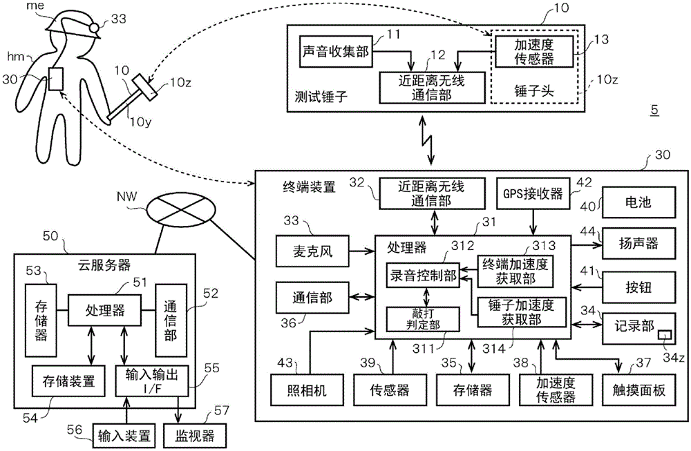
Fig. 1 is a block diagram showing the configuration of the knock detection system 5. The tap inspection system 5 has a structure including a test hammer 10, a terminal device 30, and a cloud server 50. The test hammer 10 and the terminal device 30 are connected by short-range wireless communication so as to be capable of data communication. The terminal device 30 and the cloud server 50 are connected to each other via a network NW so as to be capable of data communication. The terminal device 30 is a portable terminal or a tablet terminal.
The test hammer 10 has a hammer head 10z and a handle portion 10 y. When performing a tap test, the operator hm holds the grip portion 10y, strikes the test object with the hammer head 10z, and applies a striking force to a striking surface of the test object.
The test hammer 10 includes a sound collection unit 11, a short-range wireless communication unit 12, and an acceleration sensor 13. The sound collection unit 11 is a single microphone attached to the surface of the grip portion 10y and having directivity in the direction of the hammer head 10 z. The sound collecting unit 11 may be a microphone having no directivity, or may be a microphone array having a directivity direction formed in a predetermined direction and capable of collecting sound in the directivity direction. The sound collection unit 11 collects sounds including a hitting sound generated when the test object is hit by the hammer head 10 z.
The acceleration sensor 13 is incorporated in the hammer head 10z, detects acceleration and acceleration direction (striking force and striking direction of the hammer head 10 z) when the test object is struck by the hammer head 10z, and acquires these as detection data. The acceleration sensor 13 may acquire, as the detection data, the velocity and the inclination obtained from the value of the acceleration. Examples of the acceleration sensor include an acceleration sensor that can be mounted on an electronic substrate using a Micro Electro Mechanical Systems (MEMS) technology. The acceleration sensor 13 is capable of detecting accelerations in 3-axis (XYZ-axis) directions.
When the hammer head 10z is about to strike the inspection object, the acceleration of the hammer head 10z detected by the acceleration sensor 13 takes a large value. The acceleration direction is a direction perpendicular to and approaching the striking surface of the inspection object.
Immediately after the hammer head 10z strikes the inspection object, the acceleration of the hammer head 10z detected by the acceleration sensor 13 exhibits a minimum value (negative maximum value). The acceleration direction (deceleration direction) is a direction perpendicular to the striking surface of the inspection object and away from the striking surface.
The short-range wireless communication unit 12 performs short-range wireless communication with the terminal device 30, and transmits the sound data of the sound collected by the sound collection unit 11 and the detection data (data of the acceleration and the acceleration direction) detected by the acceleration sensor 13 to the terminal device 30. The short-range wireless communication is performed by Bluetooth (registered trademark), for example.
The terminal device 30 is carried by the operator hm. The terminal device 30 includes a processor 31, a short-range wireless communication unit 32, a microphone 33, a recording unit 34, a memory 35, a communication unit 36, a touch panel 37, an acceleration sensor 38, a sensor 39, a battery 40, a button 41, a GPS receiver 42, a camera 43, and a speaker 44.
The processor 31 controls the operations of the respective units of the terminal device 30. The processor 31 has the functions of the tap determination unit 311, the recording control unit 312, the terminal device acceleration acquisition unit 313, and the hammer acceleration acquisition unit 314. The terminal acceleration acquisition unit 313 acquires data detected by the acceleration sensor 38 incorporated in the terminal 30 for detecting the movement of the operator hm. The hammer acceleration acquisition unit 314 acquires detection data of the acceleration and the acceleration direction (inclination) of the test hammer 10 detected by the acceleration sensor 13 incorporated in the test hammer 10.
The recording control unit 312 controls an operation of recording (recording) the sound data of the sound collected by the sound collection unit 11 in the recording unit 34. The recording control unit 312 determines whether or not recording is to be performed based on the data acquired by the terminal device acceleration acquisition unit 313 and the data acquired by the hammer acceleration acquisition unit 314.
The tapping determination unit 311 evaluates the frequency characteristics of the tapping signal based on the detection data (data of the acceleration and the acceleration direction) detected by the acceleration sensor 13, and determines whether or not the tapping is performed. The tapping determination unit 311 analyzes the result of the tapping determination (tapping analysis: determination OK/NG) based on the learning data accumulated in the recording unit 34. In the tap analysis, the tap determination unit 311 may use a learning completion model obtained by machine learning using learning data.
In addition, the processor 31 accumulates the results of the tap analysis and the tap signal data in the recording section 34 to be used as learning data. The learning data may include parameters (physical quantities) such as temperature and humidity detected by the sensor 39 during the tapping and data determined to have an influence on the tapping, in addition to the tapping signal data and the result of the tapping analysis. The processor 31 transmits the learning data to the cloud server 50 via the communication unit 36 and the network NW.
The short-range wireless communication unit 32 performs short-range wireless communication with the test hammer 10 and receives measurement data from the test hammer 10.
The microphone 33 is worn on the helmet me of the operator hm. The microphone 33 may be worn on the shoulder, chest, or the like of the work clothes. The microphone 33 is a reference microphone for canceling noise, that is, canceling wind noise, surrounding noise, and the like included in the sound collected by the sound collection unit 11. Further, the microphone 33 may also be used as a microphone for collecting the tap sound of the test hammer 10. In this case, the microphone 33 may be a single microphone, or may be a microphone array that forms a directional direction in a predetermined direction and can collect sounds in the directional direction. In embodiment 2 described later, the microphone array is used.
The recording unit 34 is a storage device having a large-capacity storage medium capable of recording a large amount of knock signal data. The recording unit 34 has a tap Database (DB)34z in which a large number of characteristics of tap signal data are registered. The memory 35 is a storage medium such as ROM and RAM. The communication unit 36 is connected to the network NW by wire or wirelessly, and can perform data communication with the cloud server 50.
The touch panel 37 includes a display unit and an input unit, and functions as a User Interface (UI) for the operator hm. The acceleration sensor 38 is disposed inside the terminal device 30 carried by the operator hm, and detects the movement of the operator hm. The sensor 39 detects physical quantities such as temperature and humidity. The battery 40 is a power source of the terminal device 30, and is a secondary battery such as a lithium ion battery. The button 41 is a hard button that can be pressed by the operator hm, and includes a tap inspection start button, a tap inspection end button, and the like. The GPS receiver 42 receives GPS signals from GPS satellites to acquire position data (latitude, longitude, altitude).
The camera 43 captures an image of a striking surface of the inspection object struck by the test hammer 10 and also captures an image of the surrounding environment such as the inspection position. The image taken by the camera 43 can be either a still image or a moving image. The speaker 44 outputs sound. For example, the speaker 44 notifies the worker hm of information related to the tap check.
The cloud server 50 includes a processor 51, a communication unit 52, a memory 53, a storage device 54, and an input/output interface (I/F) 55. The communication unit 52 is connected to the network NW by wire or wireless, and can perform data communication with the terminal device 30. The memory 53 is a storage medium such as a ROM or a RAM. The storage device 54 has a large-capacity storage medium capable of recording a large amount of data. An input device 56 and a monitor 57 are connected to the input/output I/F55. The input device 56 receives various operations related to the tap check. The monitor 57 displays various information related to the tap check.
When receiving data such as acceleration (speed) and acceleration direction (inclination) of the acceleration sensor 13, tapping signal data, and results of tapping analysis from the terminal device 30 via the communication unit 52, the processor 51 accumulates the data in the storage device 54. The processor 51 performs machine learning using the data as learning data, and generates a learning completion model in the storage device 54. The processor 51 may supply the learning completion model to the terminal device 30, or may perform determination as to whether or not the terminal device 30 is a tap and tap analysis in response to a request from the terminal device 30 using the learning completion model.
The operation of the knock detection system 5 having the above-described structure is shown.
For example, consider the following case: the concrete structure such as a bridge pier of an expressway or a supporting bridge is diagnosed as an inspection object. When an internal defect (crack) exists in a concrete structure, the internal defect can be diagnosed by performing a tapping inspection.
Before starting the striking inspection, that is, before striking the inspection object with the test hammer 10, the operator hm instructs the terminal device 30 to start the inspection. This indication may be made by: the operator hm makes a "tap check start" sound, and the microphone 33 collects the sound. In addition, the following method can be used: the operator hm presses an inspection start button included in the button 41 of the terminal device 30. When there is an instruction to start the inspection, the terminal device 30 notifies the test hammer 10 via the short-range wireless communication unit 32. When the short-range wireless communication unit 12 receives the instruction, the sound collection unit 11 performs a sound collection operation for a fixed period (for example, 1 minute). The time ts (see fig. 6) at which the instruction is given is a starting point of a voice collection section in which a voice collection operation is performed for a fixed period.
Fig. 2 is a flowchart showing a tapping inspection process of the terminal device 30. When the tapping check is started, the processor 31 displays the result of the previous tapping check (yellow mark mk in fig. 13) on the touch panel 37. In addition, the processor 31 may also present the results of the last tap check audibly through the speaker 44.
In the case of performing the tap check in the constant recording mode in which the sound data of the sound collected by the sound collection unit 11 is recorded in the recording unit 34 from beginning to end, the terminal device 30 can know the event time by giving a flag to the measurement data recorded in time series. When the recording mode is not the constant recording mode, the terminal device 30 may not be provided with the flag, and the processing of steps S2, S4, and S6, which will be described later, may be omitted.
The processor 31 of the terminal device 30 performs movement stop detection processing for detecting the stop of movement of the operator hm based on the detection data output from the acceleration sensor 38 (S1). When the movement stop of the operator hm is detected, the processor 31 gives an inspection start flag mks (see fig. 6) indicating the inspection start time (S2). The examination start flag mks indicates the start of recording.
The processor 31 performs a tap detection process for detecting that the object to be inspected is tapped by the test hammer 10 (S3). The details of the tap detection processing will be described later. When the tap is detected, the processor 31 gives a tap flag mkd (S4). The processor 31 performs movement start detection processing for detecting the start of movement of the operator hm based on the detection data output from the acceleration sensor 38 (S5).
When the start of the movement of the operator hm is detected, the processor 31 gives an inspection end flag mke indicating the inspection end time (S6). At this time, the processor 31 may also notify the next position to be tapped or a sound leakage through the speaker 44.
The processor 31 determines whether or not there is a trigger to stop the tapping check (S7). The trigger for stopping the tap check is, for example, the operator hm pressing a tap stop button included in the button 41. The operator hm may sound the microphone 33 to end the inspection. If there is no trigger to stop the tap check, the processor 31 returns to the process of step S1. On the other hand, if there is a trigger to stop the tap check, the present process is terminated as it is.
In the case of the constant recording mode, the recording period is a period from when the check start flag mks is given in step S2 to when the check end flag mke is given in step S6 (see fig. 6).
Fig. 3 is a flowchart showing the movement stop detection process in step S1. The processor 31 determines whether or not the absolute value of the acceleration detected by the acceleration sensor 38 within a predetermined time is equal to or greater than a threshold value N1 (S11). The predetermined time is, for example, the time required to perform the tap inspection of 1 position. The absolute value of the acceleration of the operator tends to be as follows: the absolute value of the acceleration changes to a small value during movement or during stoppage, while the absolute value of the acceleration changes to a large value at the moment when the acceleration changes from moving to stoppage or from a stopped state to moving. Therefore, in fig. 3, when the absolute value of the detected acceleration is smaller than the threshold value N1, the processor 31 determines that the operator hm is moving, and repeats the process of step S11.
On the other hand, when the absolute value of the detected acceleration is equal to or greater than the threshold value N1, the processor 31 determines that the movement is stopped at the moment when the operator hm stops, and detects that the movement is stopped (S12). The movement stop may be displayed on the touch panel 37 or may be transmitted to the cloud server 50. After that, the processor 31 ends the present processing and returns to the original processing. In the determination processing of step S11, instead of using the absolute value of the acceleration, the direction including the acceleration may be determined.
Fig. 4 is a flowchart showing the tap detection process in step S3. The processor 31 requests the test hammer 10 via the short-range wireless communication unit 32 for data of the acceleration detected by the acceleration sensor 13. In response to the request, the short-range wireless communication unit 12 of the test hammer 10 transmits data of the acceleration detected by the acceleration sensor 13 to the terminal device 30 at short time intervals.
The processor 31 receives acceleration data from the test hammer 10 (S21). The processor 31 acquires the acceleration (for example, peak acceleration) and the acceleration direction (inclination of the hammer head 10 z) included in the received acceleration data. The processor 31 determines whether or not the acceleration of the hammer head 10z in the positive vertical direction with respect to the striking surface of the inspection target object is equal to or greater than a threshold value N2 (S22). The vertical positive direction is a direction in which the hammer head vertically approaches the striking surface (approaching direction). Here, it is determined whether or not the hammer head 10z has struck on a predetermined reference, that is, whether or not the hammer head 10z has struck the striking surface of the inspection object correctly from the front direction. The threshold value N2 is set to a value (a value suitable for the start timing of the signal for starting the tapping) for determining whether the speed of the hammer head 10z at the time of tapping is sufficient.
In the case where the acceleration in the vertically positive direction of the hammer head 10z is smaller than the threshold value N2, the processor 31 regards that the tapping has not been performed correctly with the test hammer 10, returns to the processing of step S21, and again prompts the tapping with the test hammer 10.
In step S22, if the acceleration of the hammer head 10z in the vertical positive direction with respect to the striking surface of the inspection object is equal to or greater than the threshold N2, the processor 31 then determines whether the acceleration of the hammer head 10z in the vertical negative direction with respect to the striking surface of the inspection object is equal to or greater than the threshold N3 (S23). At the moment when the hammer head 10z strikes the striking surface of the object to be inspected, the speed of the hammer head 10z becomes 0, and therefore the acceleration of the hammer head 10z is inverted and becomes a large negative value. The vertical negative direction means a direction (separating direction) in which the hammer head is vertically separated from the striking surface. The threshold N3 is set to a value suitable for the end time at which the acquisition of the tapped signal is ended. For example, the end time of the striking signal may be set to a time obtained by adding a fixed time (a time period required for the striking signal to decay) from when the acceleration of the hammer head 10z in the vertical negative direction becomes equal to or greater than the threshold value N3. Note that the end time of the tap signal may be a time obtained by adding a fixed time (a period required for attenuation of the tap signal) to the time at which the tap flag mkd is given.
When the acceleration of the hammer head 10z in the vertical negative direction is smaller than the threshold value N3, the processor 31 regards that the test hammer 10 is in the middle of the tapping, and the tapping is not completed, and the process of step S23 is repeated. When the acceleration of the hammer head 10z in the vertical negative direction becomes equal to or higher than the threshold value N3, the processor 31 ends the test of the striking of the hammer 10, and acquires the striking signal. After that, the processor 31 ends the present processing and returns to the original processing.
When the striking surface of the inspection object is struck by the test hammer 10, the sound collection unit 11 collects a striking sound emitted from the striking surface of the inspection object. The tapping signal collected by the sound collection unit 11 is, as shown in a waveform g1 of the tapping signal in fig. 6, rapidly increased after a short time from the moment of tapping and then gradually decreased.
In this way, the processor 31 extracts tapping signal data from the sound signal data collected by the sound collection unit 11 based on the detection data (measurement value) of the acceleration (speed) and the acceleration direction (inclination) of the test hammer 10 detected by the acceleration sensor 13. The processor 31 counts the number of taps by adding a value of 1 when the tap signal data can be extracted. The extracted tap signal data is recorded to the recording section 34 by the processor 31, and is also transmitted to the cloud server 50.
Here, the OK/NG of the tapping method for tapping is determined based on the value of the acceleration detected by the acceleration sensor 13, but the operator hm may determine the OK/NG of the tapping method for tapping and input the OK/NG to the terminal device 30. For example, the operator hm may perform the following operations: using a switch included in the button 41 of the terminal device 30, the switch is pressed 2 times to set OK, and the switch is pressed 1 time to set NG. The switch may be provided to the handle portion 10y of the test hammer 10. The sound collection unit 11 may collect sound data of "OK" and "NG" uttered by the operator hm. Further, the OK/NG of the tapping method for tapping may be determined according to the length of time for which the operator hm remains at the same position for repair. The operator hm may input the number of times of tapping with the test hammer 10 to determine the OK/NG of the tapping method for tapping. The determination of the tapping method by the worker hm to tap may be transmitted to the cloud server 50 as learning data together with tapping signal data and detection data of the acceleration sensor.
In addition, when the tapping method for tapping is NG, the processor 31 may display a message such as "please tap again" on the touch panel 37 to prompt the operator hm to tap again with the test hammer.
Fig. 5 is a flowchart showing the movement start detection process in step S5. The processor 31 determines whether or not the absolute value of the acceleration detected by the acceleration sensor 38 within a predetermined time is equal to or greater than a threshold value N4 (S31). The predetermined time is set to, for example, a time required to perform a tap check at 1 position. The absolute value of the acceleration of the operator tends to be as follows: the absolute value of the acceleration changes to a small value during movement or during stoppage, while the absolute value of the acceleration changes to a large value at the moment when the acceleration changes from moving to stoppage or from a stopped state to moving. Therefore, in fig. 5, when the absolute value of the detected acceleration is a value smaller than the threshold value N4, the processor 31 considers that the operator hm is in a stopped state, and repeats the process of step S31.
On the other hand, when the absolute value of the acceleration is detected to be the threshold value N4 or more in step S31, the processor 31 determines that the worker hm has started walking and detects the start of movement (S32). The movement start may be displayed on the touch panel 37 or may be transmitted to the cloud server 50. In the determination processing of step S31, instead of using the absolute value of the acceleration, the determination of the direction including the acceleration may be performed. After that, the processor 31 ends the present processing and returns to the original processing.
Note that, although the movement stop and the movement start are determined using the acceleration detected by the acceleration sensor, the movement stop and the movement start may be determined based on the position data (latitude, longitude, and altitude) obtained by the GPS receiver when the position measurement signal can be received from the GPS satellite.
Fig. 6 is a timing chart showing changes in the tap signal. In fig. 6, the following is envisaged: the operator hm strikes the test object 3 times with the test hammer 10, and the sound collection unit 11 collects the striking sounds.
When the worker hm presses the start button bn1 displayed on the touch panel 37, the tap check is started at time ts. The sound collection unit 11 starts sound collection from time ts and continues sound collection for a fixed period (for example, 1 minute).
When the striking with the hammer head 10z of the test hammer 10 is applied to the striking face of the inspection object, the acceleration of the acceleration sensor 13 becomes the threshold value N2 or more. At this time tr, the processor 31 starts the following actions: the beating signal data of the beating collected by the sound collection unit 11 is recorded in the recording unit 34. When the object is struck, as shown by the waveform g1 of the striking signal, the striking signal rapidly increases and then gradually decreases after a short time from the moment of striking.
When the time point tf is reached after a fixed time period has elapsed from the time point tr, the processor 31 ends the operation of recording the tapping signal data of the tapping collected by the sound collection unit 11 in the recording unit 34. The fixed period (time ts to time tf) is a recording period required until the knock signal is sufficiently attenuated, and is, for example, 3 seconds. Similarly, when the value of the acceleration sensor 13 becomes equal to or greater than the threshold value N2, the processor 31 repeats the following operations: the recording operation starts at time tr and ends at time tf. As a result, only the tap signal data of a fixed period (time ts to time tf), that is, the sound data at the moment of the tap, is recorded in the recording unit 34, and in fig. 6, the tap signal data of 3 times is recorded in the recording unit 34. Therefore, even if the waveform g2 of the striking sound is generated by the striking check of another operator during the blank period of the striking signal from the operator hm, the striking signal data is not recorded in the recording unit 34.
In this way, by using the value of the acceleration sensor 13, only the range of the sound at the moment of the tapping can be extracted as the tapping signal data. Therefore, it is possible to reduce the possibility of erroneous recognition of a hitting sound generated by another operator located near the operator hm. Further, when the operator hm forgets the inspection start operation (pressing of the start button, a signal for starting, or the like), the processor 31 may start recording of a sound by notifying the operator hm or by performing the inspection start operation without notifying the operator hm.
(embodiment mode 2)
When investigating the presence or absence of an internal failure (that is, a crack such as a crack) of a structure (for example, concrete), an operator strikes the surface of the structure with a hammer several times, and listens to the sound returned when the striking is performed with the ear (hereinafter referred to as "striking sound"), thereby determining whether or not the internal failure has occurred.
In contrast, japanese patent application laid-open No. 2010-271116 discloses the following technique: the structure is struck with a hammer, and the striking sound is measured with a microphone, and the state of the structure is diagnosed by a computer. In this document, the hammer has a microphone on the outer surface and an accelerometer is built in. The computer diagnoses the soundness of the structure based on the hitting signal measured by the microphone and the velocity signal obtained from the hitting force measured by the accelerometer.
In embodiment 2, the following example of a tap inspection terminal and a tap inspection data registration method will be described: the data of a striking signal when an operator strikes an object to be inspected with a hammer is registered in association with information of a position when the operator strikes the object to be inspected, and the data assists in appropriate inspection management of the object to be inspected existing in a wide area.
Since the configuration of the knock detection system in embodiment 2 is the same as that in embodiment 1, the same components as those in embodiment 1 are denoted by the same reference numerals, and the description thereof will be omitted. In embodiment 2, the sound collection part 11 of the test hammer 10 is a microphone array. The sound collection unit 11 of the test hammer 10 may be a single microphone, and the microphone 33 of the terminal device 30 (the microphone 33 attached to the helmet me of the worker hm) may be a microphone array.
The microphone array is a microphone that forms directivity in a predetermined direction and can collect sound directed in the direction, and includes a plurality of (for example, 8) microphones, a plurality of delays, and an adder. The microphone array provides a delay time corresponding to the arrival time difference at each microphone for the sound data of the sound collected by each microphone in each delayer so that the phases of all sound waves are aligned, and then adds the sound data after the delay processing in an adder. The microphone array detects sound data having directivity in a predetermined direction by changing a delay time set in the delay device, and extracts and outputs sound data having directivity in the direction. The plurality of delays and adders may be incorporated in the processor 31 instead of the microphone array. In this case, the processor 31 extracts sound data of the pointing direction using sound data collected by the plurality of microphones.
The processor 31 estimates the sound source direction based on the sound data of the directivity direction collected by the microphone array. When the sound source direction is the striking surface direction (front direction) of the inspection object struck by the hammer head 10z, the processor 31 determines that the object is struck. In addition, the processor 31 may also instruct the microphone array to form directivity in the sound source direction of the tap sound of the 1 st tap, and acquire the tap sounds of the 2 nd and subsequent taps.
Fig. 7 is a flowchart showing a tapping inspection process in embodiment 2. The processor 31 of the terminal device 30 acquires the result data of the last tap check (S51). In a case where the result data of the last tap inspection is accumulated in the cloud server 50, the processor 31 receives the result data of the last tap inspection from the cloud server 50 via the communication section 36 and the network NW. The communication unit 36 communicates with the communication unit 52 of the cloud server 50 via the network NW, and receives the result data of the last tap check accumulated in the storage device 54. The communication unit 36 stores the received result data of the last tap check in the recording unit 34. Further, in the case where the result data of the last tap inspection is stored in the recording unit 34, the processor 31 does not receive the result data from the cloud server 50, but reads out the result data of the last tap inspection stored in the recording unit 34.
The processor 31 displays the tap check screen GM1 (see fig. 13) on the touch panel 37 (S52). The tap check screen GM1 is an initial screen and includes the determination m2 of the last check result. The processor 31 determines whether or not the user has performed an operation of pressing the start button bn1 to start the tap check on the touch panel 37 (S53). If the operation to start the tapping check is not performed, the processor 31 ends the present process.
When the operation to start the tap check is performed in step S53, the processor 31 performs the check main process (S54). In this inspection main process, a main operation of the tap inspection is performed.
The processor 31 determines whether or not the user has performed an operation of pressing the interrupt button bn3 (see fig. 14) on the touch panel 37 to interrupt the tap check (S55). When the operation of interrupting the tap check is performed, the processor 31 ends the present process.
If the operation of interrupting the tapping check is not performed in step S55, the processor 31 determines whether or not the tapping check is performed a predetermined number of times and ends the tapping check (S56). The number of times of the tap check is set in advance by the operator hm and stored in the memory 35. In addition, each time the tap check is performed, the number of tap checks is counted by the processor 31. The predetermined number of times is a number of times necessary to accurately obtain the result of the tapping inspection, and is, for example, 3 times, 5 times, or the like. Note that the tap check may be ended by the user pressing an end button (not shown) displayed on the touch panel 37, not by the number of tap checks. The end button is, for example, one of buttons expanded by pressing a menu button bn 2. When the tapping check is completed after the predetermined number of times of the tapping check, the tapping check screen GM1 (see fig. 14) is updated. If the tapping check is not ended, the processor 31 returns to step S54 to continue the check main process. When the tapping check is ended in step S56, the processor 31 ends the present process.
Fig. 8 is a flowchart showing the procedure of the check main process in step S54. The processor 31 performs a tap detection process for detecting a tap in the same manner as in embodiment 1 (S61). The processor 31 determines whether tapping is detected or not as a result of the tapping detection (S62). In the case where the tapping is not detected, the processor 31 returns to the process of step S61.
On the other hand, when the tapping is detected, the processor 31 performs a tapping determination process (S63). The processor 31 displays the tap check screen GM1 (see fig. 14) including the result of the tap determination on the touch panel 37 (S64).
The processor 31 performs the tapping position detection process for detecting the position (latitude, longitude, and altitude) at which the tapping check is performed (S65). The processor 31 performs a data transmission determination process for determining whether or not to transmit the tapping signal data, the tapping determination result data, and the tapping position data (S66). Here, data including the tapping signal data, the tapping determination result data, and the tapping position data is referred to as tapping inspection data.
The processor 31 determines whether the result of the data transmission determination is that the knock check data is to be transmitted or that the knock check data is not to be transmitted (S67). If the transmission of the tap check data is not performed, the processor 31 returns to the process of step S61. On the other hand, when the knock check data is transmitted, the knock check data is transmitted to the cloud server 50 (S68). The communication unit 36 communicates with the communication unit 52 of the cloud server 50 via the network NW, and transmits the tap check data. The processor 51 of the cloud server 50 stores the tap check data received by the communication unit 52 in the storage device 54.
Fig. 9 is a flowchart showing the tap detection process in step S61. The processor 31 confirms the sound data transmitted from the test hammer 10 via the short-range wireless communication unit 32 (S71). In the test hammer 10, sound is collected by the sound collection portion 11. The short-range wireless communication unit 12 of the test hammer 10 communicates with the short-range wireless communication unit 32 of the terminal device 30, and transmits the voice data of the voice collected by the voice collection unit 11 to the short-range wireless communication unit 32. The processor 31 of the terminal device 30 receives the sound data via the short-range wireless communication unit 32. The short-range wireless communication unit 12 of the test hammer 10 transmits the sound data of the sound collected by the sound collection unit 11, and also transmits the detection data of the acceleration detected by the acceleration sensor 13. Thus, in step S71, the processor 31 of the terminal device 30 also acquires the detection data of the acceleration by the acceleration sensor 13.
The processor 31 determines whether or not the volume (sound pressure level) of the sound collected by the sound collection unit 11 is equal to or greater than the threshold N5, based on the sound data (S72). If the sound volume is less than the threshold N5, the processor 31 determines that there is no tap (S76). After that, the processor 31 ends the present processing and returns to the original processing.
In the case where the sound volume is equal to or greater than the threshold N5 in step S72, the processor 31 determines whether or not the sound data collected by the microphone 33 or the sound collection unit 11 is a sound in the target direction, that is, whether or not the direction (directivity direction) from which the sound collected by the microphone array is emitted is the target direction (S73). In the case where the sound collection part 11 is a microphone array, the processor 31 confirms whether or not the direction of the sound collected by the microphone array is a direction going from the position of the handle part 10y to which the sound collection part 11 is attached to the striking face of the hammer head 10 z. In addition, in the case where the microphone 33 is a microphone array, the processor 31 confirms whether or not the direction of the sound collected by the microphone array is the direction going from the microphone 33 worn on the helmet me to the striking face of the hammer head 10 z. If the sound is not the sound in the target direction, the processor 31 determines that there is no tap in step S76. After that, the processor 31 ends the present processing and returns to the original processing.
If the sound in the target direction is the sound in the step S73, the processor 31 determines whether or not the likelihood of the sound being similar to the tap sound, which indicates the similarity between the sound collected by the sound collection unit 11 and the tap sound, is equal to or greater than a threshold N6 (S74). The processor 31 uses the tap signal data accumulated in the recording section 34 as learning data, thereby obtaining a likelihood of being similar to the tap sound. For example, the processor 31 may acquire a learning completion model of the tap signal data from the cloud server 50 to the memory 35 in advance, input the collected sound data, and acquire a likelihood similar to the tap sound as an output thereof.
If the value is smaller than the threshold N6 in step S74, the processor 31 determines that there is no tap in step S76. In this case, the processor 31 displays a message such as "please tap again" on the touch panel 37, and prompts the operator hm to tap again with the test hammer. After that, the processor 31 ends the present processing and returns to the original processing. On the other hand, if the likelihood of similarity to the tap sound is equal to or greater than the threshold value N6, the processor 31 determines that there is a tap (S75). After that, the processor 31 ends the present processing and returns to the original processing.
Fig. 10 is a flowchart showing the tapping determination process in step S63. When it is determined in step S75 that there is a tap, the processor 31 inputs the tap signal data collected by the sound collection unit 11 (S81), and performs a feature extraction process of extracting a feature of the tap signal data (S82). In the feature extraction process, the processor 31 performs general (known) signal processing such as normalization of volume (sound pressure level), fourier transform, Mel-Frequency Cepstrum Coefficients (Mel-Frequency Cepstrum Coefficients), and noise removal on the sound data.
The processor 31 performs the following matching process: the extracted feature is determined to match the feature of the tap signal data registered in the tap Database (DB)34z stored in the recording unit 34 (S83). In this matching process, when the extracted feature matches the feature of the registered tap signal data, the processor 31 determines that the tap check is normal (OK). On the other hand, if the extracted feature does not match the feature of the registered tap signal data, the processor 31 determines that the tap check is OK.
The processor 31 determines whether the result of the matching process is the tap check normal (OK) or abnormal (NG), and stores the tap determination result in the recording unit 34 (S84). The processor 31 determines whether or not the number of times of the tap determination result is equal to or greater than the threshold value N7 (S85). When the number of times of the tap determination result is smaller than the threshold value N7, the processor 31 ends the present process and returns to the original process.
On the other hand, when the number of times of the tap determination result is equal to or greater than the threshold N7 in step S85, the processor 31 updates the tap check screen GM1 (see fig. 14) displayed on the touch panel 37 based on the tap determination result (S86). After updating the tapping check screen, the processor 31 initializes the number of tapping determination results (S87). After that, the processor 31 ends the present processing and returns to the original processing.
Fig. 11 is a flowchart showing the tap position detection process in step S65. The processor 31 acquires the measured current position information (latitude, longitude, altitude) based on the GPS signal received by the GPS receiver 42 (S91). Whether the position information acquired this time is appropriate is determined based on the position information acquired last time and the elapsed time (S92). That is, when the operator hm checks a plurality of striking positions, the time required for the striking check at 1 position and the time required to move to the next striking position can be roughly grasped. For example, if the difference between the position measurement coordinates of the previous time and the current time is good or more and the elapsed time from the previous position measurement is within good seconds, the processor 31 may move to the next position measurement coordinate in an excessively short time, and thus, the processor 31 determines that the position measurement coordinate has an error. Thus, in this case, the processor 31 corrects the current position.
When it is determined in step S92 that the position information acquired this time is appropriate, the processor 31 ends the present process and returns to the original process. On the other hand, if it is determined in step S92 that the position information acquired this time is not appropriate, the processor 31 performs current position correction processing for correcting the current position (S93). In the current position correction process, the processor 31 may correct the current position using, for example, the last position measurement coordinate and the current position measurement coordinate. In addition, the current position may be corrected based on the deviation of the position measurement coordinates of the last 5 times. For example, when the position measurement coordinates of 4 times out of the last 5 times are substantially the same and the remaining 1 time is different, the processor 31 may calculate the current position from the average of the position measurement coordinates of 4 times which are substantially the same, ignoring 1 different current position. After that, the processor 31 ends the present processing and returns to the original processing.
Fig. 12 is a flowchart showing the data transmission determination process in step S66. The processor 31 determines whether the tap check screen GM1 is updated or the tap check screen GM1 is not updated as a result of the tap determination processing in step S86 (S101). If the tap check screen GM1 is not updated, the processor 31 ends the process and returns to the original process.
On the other hand, when the tap check screen GM1 is updated in step S101, the processor 31 determines whether or not the communication unit 36 is in an environment in which the network NW can be used (S102). When the environment in which the network NW can be used is not present, the processor 31 stores the present tap signal data, the tap determination result data, and the tap position data, which cannot be transmitted, in the recording unit 34 (S104). After that, the processor 31 ends the present processing and returns to the original processing.
If the environment in which the network NW can be used is present in step S102, the processor 31 transmits the tap check data (including the tap signal data, the tap determination result data, and the tap position data) to the cloud server 50 (S103). When the processor 31 transmits the tapping signal data, it does not transmit the tapping signal data 1 time, but collectively transmits the tapping signal data of a plurality of times. The tap sound within a predetermined time (for example, 10 to 30 seconds) is regarded as the tap sound at the same inspection position and is treated as 1 group. Alternatively, a prescribed number of times (e.g., 5) of tap sounds are treated as 1 group. By setting the transmission timing to transmit to the cloud server 50 in groups, the communication frequency can be suppressed. This allows the load of the transmission processing of the terminal device 30 to be reduced and the network traffic to be suppressed. Further, the processor 31 also transmits the knock check data that has not been transmitted in the past.
The data transmitted to the cloud server 50 may include a determination of OK/NG of the operator hm. In this case, the data to be transmitted may be sound data such as "OK" and "abnormal" issued by the operator hm. The operator hm presses a determination result input button included in the button 41 of the terminal device 30, and inputs the sound data through the microphone 33. The processor 31 may perform voice recognition based on the voice data, and acquire OK or abnormal content as text information. When there is an abnormality, for example, the movement stop time is longer than usual. This is considered to be due to the time required for repair in the presence of an abnormality.
In addition, in the case where the result of the tap determination is divided into OK and NG among 1 group of tap signal data, the processor 31 transmits each tap determination result to the cloud server 50 as learning data in association with the tap signal data. The knock determination result includes, for example, OK near NG, the middle between NG and OK, and discarding of a sound that is apparently not a knock sound. The tapping determination result includes a determination result of the operator hm.
When the worker hm performs a cancel operation such as pressing a transmission stop button displayed on the touch panel 37 until the transmission of 1 set of data is completed, the processor 31 discards the transmission data. This can omit wasteful transmission. When the hitting position obtained by the GPS receiver 42 moves until 1 group of hitting signal data is transmitted, the processor 31 instructs the operator hm to hit again. Alternatively, the position coordinates obtained by the GPS receiver 42 may be corrected. For example, the time of the elapse of seconds from the registration of the last tap check may be counted, the moving distance may be calculated by multiplying the walking speed by the number of seconds, and the position coordinates obtained by the GPS receiver 42 may be corrected in consideration of the moving distance.
In addition, in the case where the GPS receiver 42 cannot be used, the position information of the entrance of the tunnel, for example, can be acquired by using the position coordinates obtained by the GPS receiver 42. In the tunnel, when the worker hm gradually moves in the tunnel, the camera 43 of the terminal device 30 may always take an image of the tunnel, and when a point whose distance from the tunnel entrance is known in advance appears in the taken image, the position coordinates obtained by the GPS receiver 42 may be corrected based on the position information, and the position where the worker hm performs the tapping inspection may be estimated. Further, when the position coordinates of the point in the tunnel are registered, the position may be estimated as a position where the worker hm performs the tapping inspection.
The communication unit 36 of the terminal device 30 communicates with the communication unit 52 of the cloud server 50 via the network NW, and transmits the data. After that, the processor 31 ends the present processing and returns to the original processing.
The processor 51 of the cloud server 50 accumulates the data received by the communication unit 52 in the storage device 54. The processor 51 performs machine learning using the data accumulated in the storage device 54 as learning data, and generates a learning completion model necessary for a tap determination by Artificial Intelligence (AI). When there is a request for the tap determination from the terminal device 30 to the cloud server 50, the processor 51 of the cloud server 50 may output a tap determination result corresponding to the input tap signal data using the generated learning completion model.
Fig. 13 is a diagram illustrating the tap check screen GM1 displayed on the touch panel 37 of the terminal device 30. On the tap check screen GM1 (initial screen), an image GZ1 including the last tap position, a state m1, a determination m2 of the last check result, a start button bn1, and a menu button bn2 are displayed. The image GZ1 may be an image captured by a camera or a graphical map on which a map is drawn. In the case of initial checking, the state m1 is blank. In the examination, the display of the state m1 is updated as shown in fig. 14. In fig. 13, in state m1, it is shown that the result of the examination performed after the present tap examination is OK. In the image GZ1, a mark mk indicating the current position, the previous examination result, the current examination result, and the number of times of non-achievement is drawn so as to be superimposed on the map cz. The map cz is a map including a road as an inspection object, and includes a road surface on the road as the inspection object. Note that, as the mark mk, for example, the mark mk indicating the current position is represented by a red (white in the figure) star shape. The result of this tap check is shown: the mark mk of OK appears as a circle of blue (black in the figure). The result of this tap check is shown: NG and the repaired mark mk appears as a gray (shown as a dot in the figure) triangle. Represents the result of the last tap check: the mark mk of OK appears as a yellow (white in the figure) circle. Represents the result of the last tap check: NG and the repaired mark mk appears as a yellow triangle. The mark mk indicating the number of times of short hits is a character mark of "not".
For example, a triangular mark mk of yellow (white in the figure) indicating that the result of the previous tapping test was NG and a circular mark mk of blue (black in the figure) indicating that the result of the current tapping test was OK are displayed so as to partially overlap each other in the vicinity of the star mark mk indicating the current position. The operator hm can easily visually confirm, by touching a panel or the like, the fact that it is determined that the inspection target object is abnormal in the past impact inspection and the place of the past impact inspection.
In this way, on the tap check screen GM1, the tap check result is displayed on the map cz in association with the tap check position. Therefore, when the operator hm performs the knock inspection, the inspection state can be easily grasped, and the convenience is improved.
Further, the image GZ1 displayed on the tap check screen GM1 may be changed in conjunction with the current position measured by the GPS receiver 42. This makes it possible for the operator hm to easily grasp the hitting inspection position near the current position during the inspection, thereby improving the operability.
Further, the shot surface of the inspection object at the time of shooting, which is captured by the camera 43, may be reflected on the shot inspection screen GM1 in conjunction with the camera 43. This shooting mode is performed by selecting the menu item expanded by the menu button bn 2. The image captured by the camera 43 may be an image at the moment of a tap (still image, moving image) or a video image recorded at all times. Further, image data of an image captured by the camera 43 may be transmitted to the cloud server 50.
Fig. 14 is a diagram illustrating a tap check screen GM1 displayed on the touch panel 37 of the terminal device 30 during the tap check. In the tap check screen GM1 (see fig. 14), before the tap determination result is obtained, "under-test" is originally displayed in the state m1, but the message is updated to "OK", "the number of tests is insufficient", "crack 80%", "void 60", "OK (crack 20%)", and "please tap again". Regarding "OK", if there are a fixed number of taps within a fixed time from the start of the examination and as a result 8 or more is OK, "OK" is displayed in state m 1. Regarding "the inspection count is insufficient", in the case where there is no tap of a fixed number of times within a fixed time from the start of the inspection, "the inspection count is insufficient" is displayed at state m 1. Regarding "please click again", when the ratio of OK to NG is close to half-to-half, or when the click signal data cannot be extracted due to the disturbing sound and thus the determination cannot be made correctly, it is considered that the number of times of the click is small, and "please click again" is displayed in a state m 1.
Instead of describing the above state by a screen, the above state may be notified by a sound. The above state may be displayed on a display worn by the operator using AR (augmented reality) technology.
Fig. 15 is a diagram showing the inspection record screen GM2 and the inspection record graph gh displayed on the monitor 57 of the cloud server 50. The processor 51 of the cloud server 50 generates an image GZ2 obtained by superimposing a mark mk2 indicating the result of the present tap check on the map cz2, based on the tap determination result data and the tap position data transmitted from the terminal device 30 in step S103. The image GZ2 may be an image captured by a camera or a graphical map on which a map is drawn. The processor 51 displays the generated image GZ2 on the monitor 57. On the examination record screen GM2 shown in fig. 15, an image GZ2 is displayed in which a mark mk2 indicating the result of the present tap examination is superimposed on the map cz 2. The mark mk2 superimposed on the map cz2 and indicating the result of the present tap examination is a blue circle except for 1 position, indicating that the result of the tap examination is OK. At 1 position, a mark mk2 indicating that the result of the tap check is NG and that the repaired one is displayed as a gray triangle. Note that the date and cause of NG as a result of the knock check are described as supplementary notes, and "2015/11/30 cracks" are described.
The processor 51 creates an inspection record graph gh representing the history of the inspection records. The vertical axis of the inspection record graph gh indicates a value obtained by digitizing normal (OK) and abnormal (NG). A higher value indicates a more normal condition, and a lower value indicates a more abnormal condition. The horizontal axis of the inspection log graph gh represents the year of inspection. The examination record graph gh corresponds to the hitting position (indicated by the gray triangular mark mk2) that is NG in the present hitting examination, which is displayed on the map cz 2. Since the tap check at 2015/11/30 is NG, the numerical value indicated by the dotted box gp is a low value.
As described above, in the tap inspection system 5 according to embodiments 1 and 2, the test hammer 10 to which the acceleration sensor 13 is attached is communicably connected to the terminal device 30 (tap inspection terminal) worn by the operator hm (user) who holds the test hammer 10. The knock detection system 5 includes the sound collection unit 11 provided in the test hammer 10 or the microphone 33 provided in the terminal device 30. The acceleration sensor 13 acquires measurement values of the speed and inclination of the test hammer 10 when the test hammer 10 strikes the object to be inspected. The terminal device 30 determines whether or not the operator hm has hit the test hammer 10 on the inspection object in accordance with a predetermined criterion based on the detection data (measurement value) of the speed and inclination of the test hammer 10 from the acceleration sensor 13. The terminal device 30 records the tapping signal data collected by the sound collection unit 11 to the cloud server 50 (external device) while tapping is performed according to a predetermined standard. Thus, it is possible to appropriately determine whether or not the operator has correctly struck the inspection object with the test hammer, and reliably extract striking signal data when the operator has struck with the test hammer.
When it is determined that the tap is not performed according to the predetermined reference, the terminal device 30 notifies the operator hm that the object to be inspected is tapped again. Thus, since the operator can be notified of the knocking again when the knocking method is not appropriate, it is possible to record the knocking signal data when the knocking is performed by the appropriate knocking method.
When recording the tap signal data in the cloud server 50, the terminal device 30 records learning data in which the tap signal data is associated with the measurement values of the speed and the inclination of the test hammer 10. Thus, it is possible to efficiently accumulate learning data for AI determination processing as to whether or not the collected sound signal data includes tap signal data extracted when a tap is performed by a tap method according to a predetermined reference, and to improve the reliability of the AI determination processing.
The terminal device 30 includes a sensor 39 (first sensor) for measuring a parameter, which is at least one of temperature and humidity. The terminal device 30 records the parameters measured by the sensor 39 while the user is tapping on the predetermined reference, including the parameters in the learning data. In this way, by registering at least one of the temperature and the humidity around the operator when the knock is appropriately performed as the learning data, the reliability of the learning data can be further improved, and the reliability of the AI determination process can be appropriately ensured.
The terminal device 30 extracts, from the sound signal data collected by the sound collection unit 11, tap signal data to be recorded in the cloud server 50, based on detection data (measurement values) of the acceleration (speed) and the acceleration direction (inclination) of the test hammer 10 from the acceleration sensor 13. Thus, even when the sound signal data when the test hammer is held and tapped by another operator located near the operator who holds the test hammer is collected by the sound collection unit, the tap signal data when the test hammer is tapped by the operator can be appropriately extracted without erroneously recognizing the tap signal data when the test hammer is tapped by the operator. In addition, even when the operator forgets the examination start operation (for example, a signal is sent to a microphone by voice, a button is pressed, or an icon on a UI), the recording of the tap signal data can be automatically started (i.e., recorded).
The terminal device 30 further includes an acceleration sensor 38 (second sensor) for detecting the movement state of the operator hm. Thus, the terminal device 30 can detect the stoppage of the operator himself, and therefore, can suppress the following: if the operator is not in the stopped state (for example, the operator is moving), the recording of the striking signal data is erroneously started due to the movement of the test hammer.
The terminal device 30 further includes a switch (input unit) included in the button 41 for inputting information on the result of the striking method in which the test hammer 10 strikes the test object. The terminal device 30 records the result information in the learning data to the cloud server 50. Thus, the terminal device 30 can register the result of the quality of the tapping method obtained based on the subjective opinion of the operator hm in the learning data, and can efficiently analyze the audio signal data (for example, whether or not the tapping method is executed according to a predetermined standard) by using the tapping signal data when the tapping method is good.
The terminal device 30 according to embodiments 1 and 2 is worn by an operator hm who grips the test hammer 10, and is connected to the cloud server 50 so as to be able to communicate with the operator hm. The terminal device 30 includes: a microphone 33; a GPS receiver 42 (position measurement unit) that acquires position information indicating the current position of the terminal device 30; a processor 31 that generates tap inspection data in which tap signal data collected by the microphone 33 during the test hammer 10 taps the object to be inspected is associated with the position information; and a communication unit 36 that transmits the generated tap check data to the cloud server 50. This makes it possible to register the striking signal data when the operator strikes the inspection object with the hammer in association with the information on the position when the operator strikes the inspection object, and to assist in the appropriate inspection management of the inspection object existing in a wide area.
The processor 31 performs a determination process of whether or not the sound data collected by the sound collection unit 11 is a tap, and determines result information indicating whether or not there is an abnormality in the inspection object tapped by the test hammer 10 based on the determination process of the terminal device 30 (in other words, the operator hm) on the position information. The communication unit 36 includes the determined result information in the tap check data, and transmits the tap check data to the cloud server 50. Thus, the terminal device 30 can determine whether or not there is a sound abnormality when the operator hm hits the inspection object with the test hammer 10 based on whether or not the sound data collected from the position information of the operator hm includes a hitting sound, and can register the result in the cloud server 50 or the like.
The processor 31 also determines result information indicating whether or not there is an abnormality in the inspection object hit by the test hammer 10 based on the sound of the operator hm at the position information collected by the sound collection unit 11. The communication unit 36 includes the determined result information in the tap check data, and transmits the tap check data to the cloud server 50. Thus, the terminal device 30 can easily set whether or not there is an abnormality when the operator hm strikes the inspection object with the test hammer 10 by using the sound of the operator hm, and can register the result in the cloud server 50 or the like.
The processor 31 also displays a mark mk (first mark) indicating the determined result information on the touch panel 37 (display unit) in association with the position information. Thus, the operator hm can easily visually confirm whether or not there is an abnormality when the test hammer 10 strikes the inspection target at the current position by touching the panel 37.
Further, the processor 31 acquires tapping inspection data at the time of a past tapping inspection from the cloud server 50 via the communication unit 36. When the result information indicating that the inspection target object has an abnormality is included in the knock inspection data in the past knock inspection, the processor 31 displays a mark mk (second mark) indicating that the abnormality has occurred on the touch panel 37 in association with the position information in the past knock inspection. Thus, the operator hm can easily visually confirm, by touching the panel or the like, the fact that the inspection target object is determined to be abnormal in the past impact inspection and the place of the past impact inspection.
The processor 31 determines whether or not the number of taps on the inspection target object at the current position is less than a predetermined number of times, based on the tap signal data collected by the sound collection unit 11. The processor 31 determines that the number of taps is less than the predetermined number, and displays a message indicating the result of the determination on the touch panel 37. This enables the operator hm to quickly recognize that the number of times of striking with the test hammer is insufficient for the inspection object at the current position, and to reliably perform the striking inspection operation for a predetermined number of times of striking.
The processor 31 generates the tap inspection data by using the tap signal data collected by the sound collection unit 11 as the tap signal data of the same terminal device 30 at the current position for a predetermined period during which the test hammer 10 has tapped the inspection target object a plurality of times. Thus, the tap signal data obtained by tapping within a predetermined period (for example, within 30 seconds) from the start of tapping can be collected as tap check data in the same location and registered in the cloud server or the like.
The processor 31 also determines result information indicating whether or not there is an abnormality in the inspection object at each of the multiple times of striking with the test hammer 10 within a predetermined period, based on the sound of the operator hm at the position information collected by the sound collection unit 11. The communication unit 36 includes the determined result information at each tap time in the tap check data, and transmits the result information to the cloud server 50. Thus, the terminal device 30 can easily set, using the sound of the operator, whether or not the operator hm has abnormality when the operator hm strikes the inspection object with a hammer for a plurality of times within a predetermined period (for example, within 30 seconds), and can minutely classify the types of the abnormality of the inspection object and register the classification in the cloud server or the like.
Further, the communication unit 36 transmits, to the cloud server 50, tap check data including tap signal data collected by the sound collection unit 11 for a predetermined period. Thus, since the same tap inspection terminal is transmitted to the cloud server or the like at the time point when tap inspection data is generated for a predetermined period (for example, 30 seconds) from the start of tapping with the hammer at the current position, the amount of communication traffic flowing through the network can be effectively reduced as compared with the case where the tap inspection data is continuously transmitted all the time.
While various embodiments have been described above with reference to the drawings, it is needless to say that the present disclosure is not limited to the examples. It is obvious that a person skilled in the art can conceive various modifications and variations within the scope of the claims, and it is needless to say that these modifications and variations also fall within the technical scope of the present disclosure.
Further, the present application is based on japanese patent applications (japanese patent application 2018-.
Industrial applicability
The present disclosure is useful for registering data of a striking signal when an operator strikes an inspection object with a hammer in association with information of a position when the operator strikes the inspection object, and for assisting appropriate inspection management of the inspection object existing in a wide area.
Description of the reference numerals
5: a tapping inspection system; 10: testing the hammer; 11: a sound collection unit; 13. 38: an acceleration sensor; 30: a terminal device; 33: a microphone; 37: a touch panel; 39: a sensor; 41: a button; 42: a GPS receiver; 50: a cloud server; 51: a processor; 52: a communication unit.