CN112093662B - Shield segment lifting machine - Google Patents
Shield segment lifting machine Download PDFInfo
- Publication number
- CN112093662B CN112093662B CN202010749177.7A CN202010749177A CN112093662B CN 112093662 B CN112093662 B CN 112093662B CN 202010749177 A CN202010749177 A CN 202010749177A CN 112093662 B CN112093662 B CN 112093662B
- Authority
- CN
- China
- Prior art keywords
- guide
- double
- chain
- rail beam
- guide rail
- Prior art date
- Legal status (The legal status is an assumption and is not a legal conclusion. Google has not performed a legal analysis and makes no representation as to the accuracy of the status listed.)
- Active
Links
Images


Classifications
-
- B—PERFORMING OPERATIONS; TRANSPORTING
- B66—HOISTING; LIFTING; HAULING
- B66C—CRANES; LOAD-ENGAGING ELEMENTS OR DEVICES FOR CRANES, CAPSTANS, WINCHES, OR TACKLES
- B66C11/00—Trolleys or crabs, e.g. operating above runways
- B66C11/14—Trolleys or crabs, e.g. operating above runways adapted to operate on crane or bridge structure of particular configuration, e.g. on reinforced concrete girders of rectangular cross-section
-
- B—PERFORMING OPERATIONS; TRANSPORTING
- B66—HOISTING; LIFTING; HAULING
- B66C—CRANES; LOAD-ENGAGING ELEMENTS OR DEVICES FOR CRANES, CAPSTANS, WINCHES, OR TACKLES
- B66C19/00—Cranes comprising trolleys or crabs running on fixed or movable bridges or gantries
-
- B—PERFORMING OPERATIONS; TRANSPORTING
- B66—HOISTING; LIFTING; HAULING
- B66C—CRANES; LOAD-ENGAGING ELEMENTS OR DEVICES FOR CRANES, CAPSTANS, WINCHES, OR TACKLES
- B66C7/00—Runways, tracks or trackways for trolleys or cranes
- B66C7/12—Devices for changing direction of travel or for transferring from one runway to another; Crossings; Combinations of tracks of different gauges
-
- B—PERFORMING OPERATIONS; TRANSPORTING
- B66—HOISTING; LIFTING; HAULING
- B66C—CRANES; LOAD-ENGAGING ELEMENTS OR DEVICES FOR CRANES, CAPSTANS, WINCHES, OR TACKLES
- B66C9/00—Travelling gear incorporated in or fitted to trolleys or cranes
- B66C9/14—Trolley or crane travel drives
-
- B—PERFORMING OPERATIONS; TRANSPORTING
- B66—HOISTING; LIFTING; HAULING
- B66C—CRANES; LOAD-ENGAGING ELEMENTS OR DEVICES FOR CRANES, CAPSTANS, WINCHES, OR TACKLES
- B66C9/00—Travelling gear incorporated in or fitted to trolleys or cranes
- B66C9/16—Travelling gear incorporated in or fitted to trolleys or cranes with means for maintaining alignment between wheels and track
-
- F—MECHANICAL ENGINEERING; LIGHTING; HEATING; WEAPONS; BLASTING
- F16—ENGINEERING ELEMENTS AND UNITS; GENERAL MEASURES FOR PRODUCING AND MAINTAINING EFFECTIVE FUNCTIONING OF MACHINES OR INSTALLATIONS; THERMAL INSULATION IN GENERAL
- F16H—GEARING
- F16H7/00—Gearings for conveying rotary motion by endless flexible members
- F16H7/08—Means for varying tension of belts, ropes, or chains
Abstract
The invention relates to a shield segment lifting machine. The shield segment lifting machine comprises: the device comprises a double-guide-rail beam fixed on a cantilever beam inside a shield machine, a duct piece lifting system fixed on the double-guide-rail beam, a conveying trolley driven to lift by the duct piece lifting system, and a trolley traveling system driving the conveying trolley to travel along the double-guide-rail beam; the vertical section of the double-guide-rail beam is in a horizontal S shape, a chain guide groove is formed in the double-guide-rail beam, and the conveying trolley travels along the chain guide groove. The shield segment conveying device can improve the conveying efficiency of shield segments, reduces conveying cost, and is safe, reliable and convenient to maintain.
Description
Technical Field
The invention relates to the technical field of shield tunneling machines, in particular to a shield segment lifting machine.
Background
At present, in the construction of the shield machine in the underground tunnel engineering, due to the characteristics of a rear matched structure, shield segments on a marshalling train cannot be directly conveyed to a segment assembling position, the shield segments on the marshalling train are lifted to a segment conveying trolley by a segment crane, and then the shield segments are conveyed to the lower part of a segment erector by the segment trolley to be grabbed and assembled by the segment erector.
Among the prior art, the section of jurisdiction loop wheel machine is by transport trolley, electric block, the cable spring reel, composition such as compensating beam, install driving motor and sprocket on the transport trolley, the sprocket meshes with the chain of installing in loop wheel machine roof beam below, walk along the chain under driving motor's drive, hoisting accessory then adopts electric block, the characteristics of this kind of technique are drive arrangement, electric block and transport trolley walk jointly, receive and release the cable through the cable reel and supply power for drive arrangement and electric block, this kind of hoisting accessory structure is complicated, with high costs, the fault rate is high, the maintenance difficulty.
Disclosure of Invention
In view of the above, it is necessary to provide a shield segment crane for solving the above problems.
A shield segment trolley comprises:
the device comprises a double-guide-rail beam fixed on a cantilever beam inside a shield machine, a duct piece lifting system fixed on the double-guide-rail beam, a conveying trolley driven to lift by the duct piece lifting system, and a trolley traveling system driving the conveying trolley to travel along the double-guide-rail beam; the vertical section of the double-guide-rail beam is in a horizontal S shape, a chain guide groove is formed in the double-guide-rail beam, and the conveying trolley travels along the chain guide groove.
In one embodiment, the segment lifting system comprises two sets of pulley blocks, two steel wire ropes and a lifting oil cylinder, wherein two ends of each steel wire rope are connected with two ends of the double-guide-rail beam, one set of pulley block is wound in the middle of each steel wire rope, a steering pulley in each set of pulley block is fixed at the end part of the lifting oil cylinder, the steering pulley is driven to transversely move by the lifting oil cylinder, and a balance beam at the bottom of the conveying trolley is driven to lift by the traction of the steel wire ropes.
In one embodiment, the balance beam is used for lifting shield segments; the pulley block further comprises a left large pulley or a right large pulley fixed on the double-guide-rail beam, two large pulleys fixed on the conveying trolley and a movable pulley connected with the end part of the balance beam, and the lifting oil cylinder moves in a telescopic mode to drive the steel wire rope and the pulley block to lift, so that the balance beam of the conveying trolley and the shield segment fixed on the balance beam are driven to lift.
In one embodiment, the trolley traveling system comprises a chain wheel driving tensioning system, a circulating chain and a chain wheel guiding device; the chain wheel driving tensioning system and the chain wheel guiding device are respectively and fixedly arranged at the rear end and the front end of the double-guide-rail beam; the circulating chain is installed inside a chain guide groove of the double-guide-rail beam, one end of the circulating chain is wound around the chain wheel driving tensioning system to be connected to one end of the conveying trolley, the other end of the circulating chain is wound around the chain wheel guiding device to be connected to the other end of the conveying trolley to form a closed loop, and the circulating chain is driven by a hydraulic motor of the chain wheel driving tensioning system to rotate so as to drive the conveying trolley to travel along the double-guide-rail beam.
In one embodiment, the sprocket drive tensioning system further comprises a first mounting seat, a driving shaft, a driving sprocket, a driven shaft and an adjustable tensioning device, the sprocket drive tensioning system is fixed to the rear end of the double-guide-rail beam through the first mounting seat, the driving shaft is connected with the hydraulic motor, the driving sprocket and the driven shaft through a first flat key, the driven shaft is connected to one end of a universal coupling, and the two ends of the universal coupling are respectively connected to the driven shaft of the sprocket drive tensioning system.
In one embodiment, the chain wheel guide device comprises a steering shaft, a second mounting seat, a steering chain wheel and a steering driven shaft, the chain wheel guide device is fixed at the front end of the double-guide-rail beam through the second mounting seat, and the steering shaft is connected with the steering chain wheel and the steering driven shaft through a second flat key.
In one embodiment, the double guide rail beam comprises two guide rail beams arranged in parallel; each guide rail beam comprises two straight guide rail beam sections and a curved guide rail beam section, and the ends of the straight guide rail beam sections and the curved guide rail beam sections are movably connected through a first connecting plate and a second connecting plate.
In one embodiment, the conveying trolley comprises a main body frame, a tug assembly and a catch wheel assembly, wherein the tug assembly and the catch wheel assembly are arranged at the top of the main body frame, and the tug assembly and the catch wheel assembly are symmetrically arranged to travel along the chain guide groove.
In one embodiment, the front side and the rear side of the conveying trolley are provided with buffer assemblies for preventing collision.
In one embodiment, the shield segment crane further comprises: be fixed in the wire rope activity of double guide rail roof beam bottom keeps off wheel assembly, the wire rope activity keeps off wheel assembly and includes two symmetry fixed mounting's spring arm-tie, fixed mounting at the attachment strap of opposite side, fixed mounting two pivot in the middle of the spring arm-tie, install have the bush of otic placode in the pivot, install the mount pad of bush bottom, install the inside first activity of mount pad keeps off the wheel.
According to the shield segment lifting machine, the double guide rail beams are arranged in the shape of bending up and down, so that the problem that shield segments on a marshalling train cannot be directly conveyed to a segment splicing position due to the characteristics of a rear matched structure in the construction of an underground tunnel project of the shield machine is solved, the shield segments on the marshalling train are lifted to a segment conveying trolley through the segment lifting machine, then the shield segments are conveyed to the position below a segment splicing machine through the segment conveying trolley, the segment splicing machine can pick and splice the shield segments, the double guide rail beams in the shape of bending up and down are directly laid at the segment splicing machine position, the conveying trolley directly conveys the shield segments to the picking position of the segment splicing machine, the conveying efficiency of the segment shield is improved, and the conveying cost is reduced; meanwhile, the segment lifting system is controlled by a hydraulic system, so that the segment lifting system is safe and reliable and is convenient to maintain.
Drawings
FIG. 1 is a perspective view of a shield segment handling machine in one embodiment;
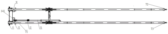
FIG. 2 is a front view of a shield segment handling machine in one embodiment;
FIG. 3 is a top view of a shield segment handling machine in one embodiment;
FIG. 4 is a schematic view of a rail beam section connection configuration in one embodiment;
FIG. 5 is a cross-sectional view of an embodiment of a sprocket driven tensioning system;
FIG. 6 is a cross-sectional view of the construction of one embodiment of the sprocket guide;
FIG. 7 is a schematic view of a transport cart according to an embodiment;
FIG. 8 is a schematic view of a balance beam configuration according to one embodiment;
FIG. 9 is a schematic view of an embodiment of a cable assembly;
FIG. 10 is a schematic illustration of the transport vehicle reaching the position of the wire rope idler assembly in one embodiment;
FIG. 11 is a schematic diagram of an embodiment of a cable catch wheel assembly.
1: the chain wheel drives the tensioning system; 2: a double guide rail beam; 3: a segment lifting system; 4: circulating the chain; 5: a sprocket guide; 6: a conveying trolley; 7: a wire rope; 8: a balance beam; 9: a steel wire rope movable catch wheel assembly; 10: a wire rope catch wheel assembly; 11: a hydraulic motor; 12: a diverting pulley; 13: a left large pulley; 14: a right large pulley; 15: a lifting oil cylinder; 16: a first connecting plate; 17: a second connecting plate; 18: a first mounting seat; 19: a drive shaft; 20: a drive sprocket; 21: a driven shaft; 22: a steering shaft; 23: a second mounting seat; 24: a steering sprocket; 25: a steering driven shaft; 26: an outer frame; 27: an inner frame; 28: a tug assembly; 29: a catch wheel assembly; 30: a buffer assembly; 31: a chain connecting seat; 32: a first pulley; 33: a second pulley; 34: a movable pulley; 35: a spring pulling plate; 36: a butt strap; 37: a rotating shaft; 38: a bushing; 39: a mounting seat; 40: a first movable catch wheel; 61: a shield segment; 71: a rear end pull plate seat; 72: a first front end platen base; 73: a second front end pulling plate seat; 141: an inner steering pulley; 201: a chain guide groove; 202: a straight rail beam section; 203: a curved guide rail beam section; 161: reserving an activity space; 171: a transverse screw; 172: a vertical screw; 101: a fixing plate; 102: a second movable catch wheel.
Detailed Description
The technical solutions in the embodiments of the present invention will be clearly and completely described below with reference to the drawings in the embodiments of the present invention, and it is obvious that the described embodiments are only a part of the embodiments of the present invention, and not all of the embodiments. All other embodiments, which can be derived from the embodiments of the present invention by a person skilled in the art without any creative effort, should be included in the protection scope of the present invention.
In one embodiment, as shown in fig. 1-3, a shield segment handling machine comprises: the device comprises a double-guide-rail beam 2 fixed on a cantilever beam inside a shield machine, a segment lifting system 3 fixed on the double-guide-rail beam 2, a conveying trolley 6 driven to lift by the segment lifting system 3, and a trolley traveling system driving the conveying trolley 6 to travel along the double-guide-rail beam 2; the vertical section of the double-guide-rail beam 2 is in a horizontal S shape, a chain guide groove 201 is formed in the double-guide-rail beam 2, and the conveying trolley 6 travels along the chain guide groove 201.
The double-guide-rail beam 2 is a track of the conveying trolley and consists of two S-shaped guide-rail beams with cross sections lying horizontally, the two S-shaped guide-rail beams are fixed on a cantilever beam in the shield tunneling machine in a suspension or screw fixing mode, the conveying trolley 6 is used for lifting shield segments 61, the conveying trolley 6 is driven to walk along the double-guide-rail beam 2 through a trolley walking system, and the conveying trolley 6 is driven to lift the shield segments 61 to a specified position.
The utility model provides a shield constructs section of jurisdiction overhead hoist, be the shape of upper and lower bending through setting up two guide rail roof beams, the shield constructs the machine in underground tunnel engineering construction has been solved, because the supporting structural feature in back, the shield that marshalling train was last constructs the section of jurisdiction and can not directly transport the section of jurisdiction and assemble the position, must through the shield section of jurisdiction overhead hoist with marshalling train on shield section of jurisdiction handling to section of jurisdiction travelling bogie, transport the shield section of jurisdiction to the below of section of jurisdiction erector by section of jurisdiction travelling bogie again, supply the section of jurisdiction erector to snatch and the problem of assembling, the double guide rail roof beam of the shape of upper and lower bending directly lays section of jurisdiction erector position, the travelling bogie directly transports the shield to the snatching position of section of jurisdiction erector, the shield has been improved the transport efficiency of section of jurisdiction and has been reduced cost of transportation.
In one embodiment, as shown in fig. 3, the segment lifting system 3 includes two sets of pulley blocks, two steel wire ropes 7 and a lifting cylinder 15, two ends of each steel wire rope 7 are connected to two ends of the double-guide-rail beam 2, the middle of each steel wire rope 7 bypasses one set of pulley block, a diverting pulley 12 in each set of pulley block is fixed at the end of the lifting cylinder 15, the lifting cylinder 15 drives the diverting pulley 12 to move transversely, and the steel wire rope 7 drives the balance beam 8 at the bottom of the conveying trolley 6 to lift.
Two sets of pulley blocks are distributed on two sides of the double-guide-rail beam, one set of pulley block corresponds to one steel wire rope 7, one end of the steel wire rope 7 is connected with a rear-end pull plate seat 71 of the double-guide-rail beam 2, and the other end of the steel wire rope 7 is connected with a first front-end pull plate seat 72 or a second front-end pull plate seat 73 of the double-guide-rail beam 2. Each set of pulley block comprises a diverting pulley 12, one end of the steel wire rope 7 is connected with a rear end pull plate seat 71, then bypasses the diverting pulley 12, then bypasses other pulleys of the pulley block, and is finally connected with a first front end pull plate seat 72 or a second front end pull plate seat 73 of the double-guide-rail beam 2. And a balance beam 8 at the bottom of the conveying trolley 6 is connected with a movable pulley in the pulley block. In the embodiment, the balance beam 8 is driven to lift through the steel wire rope, the pulley block and the lifting oil cylinder, the lifting oil cylinder is shared, the synchronous lifting of the two ends of the balance beam 8 is ensured, and the cost is saved.
In one embodiment, as shown in fig. 3, the balance beam 8 is used for lifting shield segments; the pulley block further comprises a left large pulley 13 or a right large pulley 14 fixed on the double-guide-rail beam 2, two large pulleys fixed on the conveying trolley 6 and a movable pulley 34 connected with the end part of the balance beam 8, and the lifting oil cylinder 15 moves in a telescopic mode to drive the steel wire rope 7 and the pulley block to lift, so that the balance beam 8 of the conveying trolley 6 and the shield segment fixed on the balance beam 8 are driven to lift.
The two large pulleys of the conveying trolley comprise a first pulley 32 and a second pulley 33 (as shown in fig. 7) which are symmetrically arranged in an internal frame of the conveying trolley, two ends of the balance beam 8 are respectively connected with a movable pulley 34, and the lifting of the movable pulley 34 drives the lifting of the balance beam 8. Specifically, one end of one of the steel wire ropes is connected with the rear end pull plate seat 71 of the double-guide-rail beam 2, and the other end of the steel wire rope passes around the diverting pulley 12, then passes around the inner diverting pulley 141, then passes around the diverting pulley 14, passes around the first pulley 32, the movable pulley 34 and the second pulley 33 of the conveying trolley 6, and is connected with the first front end pull plate seat 72 of the double-guide-rail beam 2; one end of the other steel wire rope is connected with the rear end pull plate seat 71 of the double-guide-rail beam 2, and the other end of the steel wire rope passes around the diverting pulley 12, then passes around the diverting pulley 13, passes through the first pulley 32, the movable pulley 34 and the second pulley 33 of the conveying trolley 6 and is connected with the second front end pull plate seat 73 of the double-guide-rail beam 2.
In one embodiment, as shown in fig. 1, the trolley traveling system comprises a sprocket-driven tensioning system 1, a circulating chain 4 and a sprocket guide device 5; the chain wheel driving tensioning system 1 and the chain wheel guide device 5 are fixedly arranged at the rear end and the front end of the double-guide-rail beam 2 respectively; the circulating chain 4 is installed inside a chain guide groove 201 of the double-guide-rail beam 2, one end of the circulating chain 4 bypasses the chain wheel driving tensioning system 1 and is connected to one end of the conveying trolley 6, the other end of the circulating chain 4 bypasses the chain wheel guiding device 5 and is connected to the other end of the conveying trolley 6 to form a closed loop, and the circulating chain 4 is driven by the hydraulic motor 11 of the chain wheel driving tensioning system 1 to rotate so as to drive the conveying trolley 6 to walk along the double-guide-rail beam 2.
The conveying trolley 6 comprises two main body frames, each main body frame is movably connected with one of the double guide rail beams 2, each main body frame is fixedly connected with at least one circulating chain 4, and the bottom of each frame is provided with a movable pulley 34; wherein, chain connecting seats 31 (shown in fig. 7) are provided at the front and rear ends of each main body frame for connecting with the circulating chain 4. The circulating chain 4 drives the tensioning system 1 to rotate through the chain wheel, the chain wheel drives the tensioning system 1 to be driven by the hydraulic motor 11, the chain wheel guiding device 5 is equivalent to a driven wheel of the chain wheel driving tensioning system 1, and when the chain wheel driving tensioning system 1 rotates, the chain wheel guiding device 5 is driven to rotate through the circulating chain 4, and meanwhile, the conveying trolley 6 is pulled to walk on the double-guide-rail beam 2.
In one embodiment, as shown in fig. 5, the sprocket driving tensioning system 1 further includes a first mounting seat 18, a driving shaft 19, a driving sprocket 20, a driven shaft 21, and an adjustable tensioning device, the sprocket driving tensioning system 1 is fixed to the rear end of the double-guide-rail beam 2 through the first mounting seat 18, the driving shaft 19 is connected to the hydraulic motor 11, the driving sprocket 20, and the driven shaft 21 through a first flat key, the driven shaft 21 is connected to one end of a universal coupling, and two driven shafts 21 of the sprocket driving tensioning system 1 are connected to two ends of the universal coupling respectively.
Optionally, the number of the driving chain wheels 20 is two, the two circulating chains 4 are connected, the driving chain wheels 20 are movably connected with the circulating chains 4, the driving chain wheels 20 are provided with chain teeth to be clamped into the circulating chains 4, and the driving chain wheels 20 rotate to drive the circulating chains 4 to rotate.
In this implementation, driven shaft 21 is connected respectively at universal joint both ends, can guarantee the synchronism of the operation of the left and right guide rail sprocket actuating system of symmetrical arrangement.
In one embodiment, as shown in fig. 6, the sprocket guide 5 includes a steering shaft 22, a second mounting seat 23, a steering sprocket 24, and a steering driven shaft 25, the sprocket guide 5 is fixed to the front end of the double-guide-rail beam 2 through the second mounting seat 23, and the steering shaft 22 is connected to the steering sprocket 24 and the steering driven shaft 25 through a second flat key.
Optionally, the number of the steering chain wheels 24 is two, the two steering chain wheels are respectively connected with the two circulating chains 4, the steering chain wheels 24 are movably connected with the circulating chains 4, the steering chain wheels 24 are provided with chain teeth which are clamped into the circulating chains 4, and the circulating chains 4 rotate to drive the steering chain wheels 24 to rotate. The steering shaft 22 is connected with the steering chain wheel 24 and the steering driven shaft 25 through a second flat key, so that the running synchronism of the circulating chains 4 symmetrically arranged on the two main body frames is ensured.
In one embodiment, as shown in fig. 1 and 4, the double-guide-rail beam 2 comprises two guide-rail beams arranged in parallel; each guide rail beam comprises two straight guide rail beam sections and a curved guide rail beam section, and the ends of the straight guide rail beam sections and the curved guide rail beam sections are movably connected through a first connecting plate 16 and a second connecting plate 17.
Fig. 4A is a front view of end connection of a straight rail beam section 202 and a curved rail beam section 203, fig. 4B is a top cross-sectional view of end connection of the straight rail beam section 202 and the curved rail beam section 203, in fig. 4A, a first connecting plate 16 and a second connecting plate 17 are fixed by screws, the first connecting plate 16 is in an "L" -shaped plate-shaped structure, the second connecting plate 17 is in an "L" -shaped flat structure, the "L" -shaped bottom of the second connecting plate 17 faces the center of the double rail beam 2, the first connecting plate 16 is parallel to the double rail beam 2, a movable space 161 is reserved when the straight rail beam section 202 and the curved rail beam section 203 are connected by the first connecting plate 16 and the second connecting plate 17, and the first connecting plate 16 and the second connecting plate 17 are fixedly connected by a transverse screw 171 and a vertical screw 172. In this embodiment, realize through first connecting plate 16 and second connecting plate 17 the swing joint of straight guide rail beam section and bent guide rail beam section can guarantee that straight guide rail beam section and bent guide rail beam section can both be certain angle in horizontal and vertical, turn to and go up the downhill path range when can adapt to the tunnel that the shield constructs the machine excavation.
In one embodiment, as shown in fig. 7 and 10, the conveying trolley 6 comprises a main body frame, a tug assembly 28 and a catch wheel assembly 29, the tug assembly 28 and the catch wheel assembly 29 are arranged on the top of the main body frame, and the tug assembly 28 and the catch wheel assembly 29 are symmetrically arranged to run along the chain guide groove 201.
Wherein, fig. 7A is a front view of the frame of the conveying trolley, fig. 7B is a left cross-sectional view of the frame of the conveying trolley, the conveying trolley 6 comprises two main frames, each main frame comprises an outer frame 26 and an inner frame 27, the top of the outer frame 26 is fixed with the tug assembly 28 and the catch wheel assembly 29, the tug assembly 28 is provided with vertical walking wheels to rotate and walk at the bottom of the chain guide groove 201, and the catch wheel assembly 29 is provided with horizontal walking wheels to rotate and walk along the bottom edge of the chain guide groove 201. Alternatively, chain coupling seats 31 are provided at both ends of the outer frame 26, and a first pulley 32 and a second pulley 33 are provided in the middle of the inner frame 27.
In this embodiment, the trolley is driven to travel along the double-guide-rail beam 2 by the tug assembly 28 and the catch wheel assembly 29, so that friction can be reduced, and power consumption in the traveling process can be reduced.
In one embodiment, as shown in fig. 7 and 10, the front and rear sides of the transport carriage 6 are provided with bumper assemblies 30 for preventing collision. In this embodiment, the buffer assembly 30 can prevent the transportation cart from colliding with the obstacle during the front and rear movement processes to cause loss.
In one embodiment, the shield segment handling machine, as shown in fig. 9 and 10, further includes: be fixed in the wire rope activity that double guide rail roof beam 2 bottom keeps off wheel assembly 9, wire rope activity keeps off wheel assembly 9 and includes two symmetry fixed mounting's spring arm-tie 35, fixed mounting 36, fixed mounting two at the access strap of opposite side pivot 37 in the middle of the spring arm-tie 35, install have the bush 38 of otic placode in the pivot, install the mount pad 39 of bush 38 bottom, install the inside 39 first activity of mount pad keeps off wheel 40.
Fig. 9A is a front view of the movable wire rope catch wheel assembly, fig. 9B is a left cross-sectional view of the movable wire rope catch wheel assembly, and fig. 9C is a top view of the movable wire rope catch wheel assembly. The steel wire rope movable catch wheel assembly 9 is fixed at the bottom of the double-guide-rail beam 2 through the upper ends of the spring pull plate 35, the butt strap 36 and the rotating shaft 37, the bushing 38 can rotate relative to the rotating shaft 37 when stressed, the bushing 38 rotates to drive the butt strap 36 to rotate, when the bushing 38 rotates to a certain angle, a gap is reserved between the bushing 38 and the butt strap 36 for the conveying trolley to pass through, when the bushing 38 is not stressed, the bushing returns through the spring, the butt strap 36 is of an L-shaped flat plate-shaped structure, one end of the mounting seat 39 is in contact with the upper portion of the L-shaped bottom of the butt strap 36 (as shown in figure 9B), and when the conveying trolley is at a downhill section of the double-guide-rail beam 2 or a straight guide-rail beam section at the front end of the double-rail beam 2, the steel wire rope 7 is in contact with the first movable catch wheel 40 to prevent falling and avoid friction. Optionally, the bottom of the double-guide-rail beam 2 is connected with three pairs of steel wire rope movable catch wheel assemblies 9.
In the implementation, the steel wire rope movable catch wheel assemblies are symmetrically arranged below the upper arc line section of the double-guide-rail beam, so that the conveying trolley can pass through without obstacle, and can be reset through the spring to support the steel wire rope after the conveying trolley passes through, and the steel wire rope is prevented from falling.
In one embodiment, as shown in fig. 11, the shield segment handling machine further includes: and the steel wire rope catch wheel assembly 10 is fixed at the bottom of the double-guide-rail beam 2, and the steel wire rope catch wheel assembly 10 comprises two fixed plates 101 and a second movable catch wheel 102.
The fixed plate 101 is fixedly connected with the bottom of the double-guide-rail beam 2, the end part of the second movable catch wheel 102 is provided with a rotating shaft which is movably connected with the bottom of the fixed plate 101, and the second movable catch wheel 102 is positioned in the middle of the two fixed plates 101 and can rotate relative to the two fixed plates 101. Optionally, the bottom of the double-guide-rail beam 2 is connected with three pairs of steel wire rope catch wheel assemblies 10. In the implementation, the steel wire rope catch wheel assemblies are symmetrically arranged below the lower arc line section of the double guide rail beam so that the steel wire ropes avoid friction on the lower surface of the guide rail beam.
The technical features of the embodiments described above may be arbitrarily combined, and for the sake of brevity, all possible combinations of the technical features in the embodiments described above are not described, but should be considered as being within the scope of the present specification as long as there is no contradiction between the combinations of the technical features.
The above-mentioned embodiments only express several embodiments of the present invention, and the description thereof is more specific and detailed, but not construed as limiting the scope of the invention. It should be noted that, for a person skilled in the art, several variations and modifications can be made without departing from the inventive concept, which falls within the scope of the present invention. Therefore, the protection scope of the present patent shall be subject to the appended claims.
Claims (10)
1. The utility model provides a shield constructs section of jurisdiction handling machine which characterized in that includes:
the device comprises a double-guide-rail beam (2) fixed on a cantilever beam in the shield machine, a duct piece lifting system (3) fixed on the double-guide-rail beam (2), a conveying trolley (6) driven to lift by the duct piece lifting system (3), and a trolley traveling system for driving the conveying trolley (6) to travel along the double-guide-rail beam (2); wherein the content of the first and second substances,
the utility model discloses a double guide rail roof beam (2) vertical cross-section is horizontal "S" type, double guide rail roof beam (2) inside sets up chain guide way (201), travelling bogie (6) are followed chain guide way (201) walking, double guide rail roof beam (2) are gone up the arc line section below and are symmetrically installed wire rope activity and keep off wheel assembly (9), and wire rope activity keeps off wheel assembly (9) and pass through the upper end of spring arm-tie (35), attachment strap (36) and pivot (37) and be fixed in double guide rail roof beam (2) bottom, can rotate for pivot (37) when bush (38) atress, and bush (38) rotate and drive attachment strap (36) and rotate, through spring reset when bush (38) do not atress.
2. The shield segment lifting machine of claim 1, wherein the segment lifting system (3) comprises two sets of pulley blocks, two steel wire ropes (7) and a lifting oil cylinder (15), wherein two ends of each steel wire rope (7) are connected with two ends of the double guide rail beam (2), the middle of each steel wire rope (7) bypasses one set of pulley block, a steering pulley (12) in each set of pulley block is fixed at the end part of the lifting oil cylinder (15), the steering pulley (12) is driven to transversely move by the lifting oil cylinder (15), and a balance beam (8) at the bottom of the conveying trolley (6) is driven to lift by the steel wire ropes (7).
3. The shield segment handling machine of claim 2, wherein the balance beam (8) is used for handling shield segments; the pulley block further comprises a left large pulley (13) or a right large pulley (14) fixed on the double-guide-rail beam (2), two large pulleys fixed on the conveying trolley (6) and a movable pulley (34) connected with the end of the balance beam (8), and the steel wire rope (7) and the pulley block are driven to lift through telescopic motion of the lifting oil cylinder (15), so that the balance beam (8) and the shield segment fixed on the balance beam (8) of the conveying trolley (6) are driven to lift.
4. The shield segment lifting machine of claim 1, wherein the trolley traveling system comprises a sprocket-driven tensioning system (1), a circulating chain (4) and a sprocket guide device (5); the chain wheel driving tensioning system (1) and the chain wheel guiding device (5) are fixedly arranged at the rear end and the front end of the double-guide-rail beam (2) respectively; the chain guide groove (201) inside double-guide rail roof beam (2) is installed in circulation chain (4), the one end of circulation chain (4) is walked around sprocket drive rises and tightly system (1) and connects one of transport trolley (6) is served, and the other end is walked around sprocket guider (5) are connected on the other end of transport trolley (6), form closed loop, through hydraulic motor (11) drive of sprocket drive rises and tightly system (1) circulation chain (4) rotate, thereby drive transport trolley (6) are followed double-guide rail roof beam (2) walking.
5. The shield segment lifting machine of claim 4, wherein the sprocket driving tensioning system (1) further comprises a first mounting seat (18), a driving shaft (19), a driving sprocket (20), a driven shaft (21) and an adjustable tensioning device, the sprocket driving tensioning system (1) is fixed at the rear end of the double-guide-rail beam (2) through the first mounting seat (18), the driving shaft (19) is connected with the hydraulic motor (11), the driving sprocket (20) and the driven shaft (21) through a first flat key, the driven shaft (21) is connected to one end of a universal coupling, and the two ends of the universal coupling are respectively connected with the driven shaft (21) of the sprocket driving tensioning system (1).
6. The shield segment lifting machine of claim 4, wherein the chain wheel guide device (5) comprises a steering shaft (22), a second mounting seat (23), a steering chain wheel (24) and a steering driven shaft (25), the chain wheel guide device (5) is fixed at the front end of the double-guide-rail beam (2) through the second mounting seat (23), and the steering shaft (22) is connected with the steering chain wheel (24) and the steering driven shaft (25) through second flat keys.
7. The shield segment trolley of claim 1, wherein the double guide rail beams (2) comprise two guide rail beams arranged in parallel; each guide rail beam comprises two straight guide rail beam sections and a curved guide rail beam section, and the ends of the straight guide rail beam sections and the curved guide rail beam sections are movably connected through a first connecting plate (16) and a second connecting plate (17).
8. The shield segment lifting machine of claim 1, wherein the conveying trolley (6) comprises a main body frame, a tug assembly (28) and a catch wheel assembly (29), the tug assembly (28) and the catch wheel assembly (29) are arranged at the top of the main body frame, and the tug assembly (28) and the catch wheel assembly (29) are symmetrically arranged to run along the chain guide groove (201).
9. The shield segment trolley according to any one of claims 1-8, characterized in that the front and rear sides of the conveying trolley (6) are provided with impact-proof buffer assemblies (30).
10. The shield segment handling machine of any one of claims 1-8, further comprising: be fixed in wire rope activity of two guide rail roof beams (2) bottom keeps off wheel assembly (9), wire rope activity keeps off wheel assembly (9) and includes spring arm-tie (35), fixed mounting (36), the fixed mounting of two symmetry fixed mounting at the opposite side and takes turns (37), installs in the middle of spring arm-tie (35) pivot bush (38) that have the otic placode, install mount pad (39), the installation of bush (38) bottom keep off wheel (40) in the inside first activity of mount pad (39).
Priority Applications (1)
| Application Number | Priority Date | Filing Date | Title |
|---|---|---|---|
| CN202010749177.7A CN112093662B (en) | 2020-07-30 | 2020-07-30 | Shield segment lifting machine |
Applications Claiming Priority (1)
| Application Number | Priority Date | Filing Date | Title |
|---|---|---|---|
| CN202010749177.7A CN112093662B (en) | 2020-07-30 | 2020-07-30 | Shield segment lifting machine |
Publications (2)
| Publication Number | Publication Date |
|---|---|
| CN112093662A CN112093662A (en) | 2020-12-18 |
| CN112093662B true CN112093662B (en) | 2022-07-12 |
Family
ID=73750520
Family Applications (1)
| Application Number | Title | Priority Date | Filing Date |
|---|---|---|---|
| CN202010749177.7A Active CN112093662B (en) | 2020-07-30 | 2020-07-30 | Shield segment lifting machine |
Country Status (1)
| Country | Link |
|---|---|
| CN (1) | CN112093662B (en) |
Families Citing this family (2)
| Publication number | Priority date | Publication date | Assignee | Title |
|---|---|---|---|---|
| CN117049338B (en) * | 2023-10-13 | 2023-12-15 | 中交三航(南通)海洋工程有限公司 | Shield constructs section of jurisdiction overhead hoist |
| CN117465907B (en) * | 2023-12-28 | 2024-03-19 | 中铁工程服务有限公司 | Continuous conveying device and shield system |
Citations (6)
| Publication number | Priority date | Publication date | Assignee | Title |
|---|---|---|---|---|
| CN201334922Y (en) * | 2009-01-08 | 2009-10-28 | 上海地铁盾构设备工程有限公司 | Car walking device with double rails and double beams |
| CN103133017A (en) * | 2013-03-11 | 2013-06-05 | 辽宁三三工业有限公司 | Pipe piece rapid lifting device |
| CN205472368U (en) * | 2016-01-29 | 2016-08-17 | 甘肃建投装备制造有限公司 | Shield constructs quick -witted section of jurisdiction conveyor system |
| CN110056378A (en) * | 2018-12-30 | 2019-07-26 | 中船重型装备有限公司 | A kind of shield machine S bend pipe piece loop wheel machine beam |
| CN110388219A (en) * | 2019-08-02 | 2019-10-29 | 中铁山河工程装备股份有限公司 | A kind of shield machine twin beams fixed point driving section of jurisdiction handling apparatus |
| CN213059937U (en) * | 2020-07-30 | 2021-04-27 | 中铁山河工程装备股份有限公司 | Shield segment lifting machine |
-
2020
- 2020-07-30 CN CN202010749177.7A patent/CN112093662B/en active Active
Patent Citations (6)
| Publication number | Priority date | Publication date | Assignee | Title |
|---|---|---|---|---|
| CN201334922Y (en) * | 2009-01-08 | 2009-10-28 | 上海地铁盾构设备工程有限公司 | Car walking device with double rails and double beams |
| CN103133017A (en) * | 2013-03-11 | 2013-06-05 | 辽宁三三工业有限公司 | Pipe piece rapid lifting device |
| CN205472368U (en) * | 2016-01-29 | 2016-08-17 | 甘肃建投装备制造有限公司 | Shield constructs quick -witted section of jurisdiction conveyor system |
| CN110056378A (en) * | 2018-12-30 | 2019-07-26 | 中船重型装备有限公司 | A kind of shield machine S bend pipe piece loop wheel machine beam |
| CN110388219A (en) * | 2019-08-02 | 2019-10-29 | 中铁山河工程装备股份有限公司 | A kind of shield machine twin beams fixed point driving section of jurisdiction handling apparatus |
| CN213059937U (en) * | 2020-07-30 | 2021-04-27 | 中铁山河工程装备股份有限公司 | Shield segment lifting machine |
Also Published As
| Publication number | Publication date |
|---|---|
| CN112093662A (en) | 2020-12-18 |
Similar Documents
| Publication | Publication Date | Title |
|---|---|---|
| CN112093662B (en) | Shield segment lifting machine | |
| CN213059937U (en) | Shield segment lifting machine | |
| CN211008681U (en) | Double-beam fixed-point driving duct piece hoisting device of shield machine | |
| CN112520613B (en) | Moving machine | |
| CN106812546B (en) | Duct piece transfer device and tunnel boring machine | |
| CN116101710A (en) | Tunnel tray type continuous conveying system | |
| CN207877140U (en) | Eight wheel electric overhead travelling cranes | |
| JP2994935B2 (en) | Bridge overhang erection method and equipment | |
| CN211168548U (en) | Single-track transverse belt conveyor | |
| CN211230513U (en) | Tunnel inner rail lower structure assembling device | |
| CN210175711U (en) | Carrying device and lifting device | |
| CN109956362B (en) | Cable clamping and conveying traction device | |
| CN217229007U (en) | Belt storage bin of belt conveyor for preventing deviation of adhesive belt | |
| JPH05131920A (en) | Hybrid-type circulation cableway usable with railway | |
| CN216515195U (en) | Beam carrying device and beam carrying equipment | |
| CN212581030U (en) | Tunnel material transportation device | |
| CN111550269A (en) | Self-propelled removes inverted arch landing stage | |
| CN220059076U (en) | High-speed carrier | |
| CN201598106U (en) | Novel upper trolley lifting hook traversing mechanism of shipbuilding gantry crane | |
| CN110761813A (en) | Waterproof board trolley capable of automatically feeding | |
| CN219385829U (en) | Rail exchanging operation system | |
| CN219823451U (en) | Travelling trolley for cable crane | |
| CN217099955U (en) | Steel wire rope group type train traction device | |
| CN217050244U (en) | Head transmission structure with tensioning function for electric roller belt conveyor | |
| CN213976674U (en) | Lifting beam for monorail crane |
Legal Events
| Date | Code | Title | Description |
|---|---|---|---|
| PB01 | Publication | ||
| PB01 | Publication | ||
| SE01 | Entry into force of request for substantive examination | ||
| SE01 | Entry into force of request for substantive examination | ||
| GR01 | Patent grant | ||
| GR01 | Patent grant |