CN111975682A - Industrial robot composite clamp - Google Patents
Industrial robot composite clamp Download PDFInfo
- Publication number
- CN111975682A CN111975682A CN202010892137.8A CN202010892137A CN111975682A CN 111975682 A CN111975682 A CN 111975682A CN 202010892137 A CN202010892137 A CN 202010892137A CN 111975682 A CN111975682 A CN 111975682A
- Authority
- CN
- China
- Prior art keywords
- lead screw
- clamping plates
- base
- slider
- workpiece
- Prior art date
- Legal status (The legal status is an assumption and is not a legal conclusion. Google has not performed a legal analysis and makes no representation as to the accuracy of the status listed.)
- Granted
Links
Images


Classifications
-
- B—PERFORMING OPERATIONS; TRANSPORTING
- B25—HAND TOOLS; PORTABLE POWER-DRIVEN TOOLS; MANIPULATORS
- B25B—TOOLS OR BENCH DEVICES NOT OTHERWISE PROVIDED FOR, FOR FASTENING, CONNECTING, DISENGAGING OR HOLDING
- B25B11/00—Work holders not covered by any preceding group in the subclass, e.g. magnetic work holders, vacuum work holders
Landscapes
- Engineering & Computer Science (AREA)
- Mechanical Engineering (AREA)
- Manipulator (AREA)
Abstract
The invention relates to a composite clamp of an industrial robot, which comprises a base and a sliding block, wherein two parallel sliding rods and a lead screw are arranged on the base, an output shaft of a motor is fixedly connected with the left end of the lead screw, the sliding block is sleeved on the sliding rods in a sliding manner, the sliding block is in threaded fit connection with the corresponding part of the lead screw, clamping plates are arranged on the opposite sides of the two sliding blocks, two springs are arranged between the sliding block and the clamping plates, pull ropes are correspondingly arranged on the front edge and the rear edge of each clamping plate, the end parts of the pull ropes are fixedly connected with the clamping plates, the pull ropes are wound on guide wheels, rotating shafts on; when the workpiece is measured, the motor is utilized to drive the screw rod to rotate, the clamping plates are utilized to clamp the left side and the right side of the workpiece, the clamping plates compress the spring, the clamping plates drive the guide wheel to rotate through the pull rope, the limiting plates rotate along with the guide wheel, when the clamping plates are utilized to clamp the workpiece, the limiting plates clamp the front side and the rear side of the workpiece, and the workpiece can be prevented from inclining to the front side and the rear side.
Description
Technical Field
The invention belongs to the technical field of industrial equipment, and particularly relates to a composite clamp for an industrial robot.
Background
Industrial robot is widely used among various mills, in the work piece course of working to industrial robot, need use the very high composite jig of precision, traditional composite jig is after with the work piece centre gripping, especially square work piece, for convenient placing, the left and right sides of centre gripping work piece is generally set to anchor clamps, at the in-process with the centre gripping of part left and right sides, the work piece inclines to precedence both sides easily, and direct centre gripping work piece four sides can lead to anchor clamps too complicated, occupation space is too big, be unfavorable for placing the work piece in the anchor clamps, consequently, be not enough to current technique, need carry out further improvement.
Disclosure of Invention
In view of the above, the present invention provides a composite fixture for an industrial robot to solve the above problems.
In order to achieve the purpose, the technical scheme adopted by the invention is as follows: a composite clamp of an industrial robot comprises a base with a convex middle part at the upper side, sliding blocks distributed at two sides of the convex middle part, two parallel sliding rods and a lead screw arranged on the base, wherein the lead screw is positioned between the sliding rods, two ends of the sliding rods and the lead screw are respectively connected with the corresponding edges of the base in a rotating way, a motor is fixed at the left side of the base, an output shaft of the motor is fixedly connected with the left end of the lead screw, the sliding rods and the lead screw penetrate through the convex part at the middle part of the base, the sliding blocks are sleeved on the sliding rods in a sliding way, the sliding blocks are connected with the corresponding parts of the lead screw in a threaded fit way, clamping plates are arranged at the opposite sides of the two sliding blocks, the clamping plates slide on the sliding blocks, two springs are arranged between the sliding blocks and the clamping plates, one, the rotating shaft of the guide wheel is rotationally connected with the sliding block, and a limiting plate is fixed on the rotating shaft.
Preferably, the left and right threads of the screw are selected in opposite directions.
Preferably, one side, deviating from the pivot, of the limiting plate is provided with a cylinder, so that workpieces can be clamped conveniently.
The invention has the beneficial effects that: when a workpiece is measured, a motor is used for driving a lead screw to rotate, the slide blocks are driven to slide on the slide rods, the two slide blocks are close to each other, the clamping plates are close to the workpiece, the clamping plates compress the springs while clamping the left side and the right side of the workpiece, the clamping plates drive the guide wheels to rotate through the pull ropes, the limiting plates rotate along with the guide wheels, and the cylinders of the limiting plates clamp the front side and the rear side of the workpiece; when the clamping plate is used for clamping the workpiece, the limiting plates clamp the front side and the rear side of the workpiece, so that the workpiece can be prevented from inclining to the front side and the rear side.
Drawings
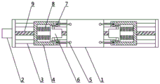
FIG. 1 is a front view structural diagram of the present invention;
FIG. 2 is a first top view of the present invention;
FIG. 3 is a second top view of the present invention.
Reference numbers in the figures: 1, a base; 2, a motor; 3, a sliding rod; 4, a sliding block; 5, limiting plates; 6, clamping plates; 7 guide wheels; 8, a spring; 9, a screw rod; 10 workpiece.
Detailed Description
The invention is described in further detail below with reference to the following figures and detailed description:
referring to fig. 1-3, a composite fixture for an industrial robot comprises a base 1 with a convex middle part at the upper side and sliding blocks 4 distributed at two sides of the convex middle part, wherein the base 1 is provided with two parallel sliding rods 3 and a lead screw 9, the lead screw 9 is positioned between the two sliding rods 3, two ends of the sliding rods 3 and the lead screw 9 are respectively connected with the corresponding edges of the base 1 in a rotating manner, the left side of the base 1 is fixed with a motor 2, an output shaft of the motor 2 is fixedly connected with the left end of the lead screw 9, the left part and the right part of the lead screw 9 are opposite in thread direction, the sliding rods 3 and the lead screw 9 both pass through the convex middle part of the base 1, the sliding blocks 4 are sleeved on the sliding rods 3 in a sliding manner, the sliding blocks 4 are in thread fit connection with the corresponding parts of the lead screw 9, clamping plates 6 are arranged at opposite sides of the two sliding blocks 4, the other end of the spring 8 is fixedly connected with the clamping plate 6, the front edge and the rear edge of the clamping plate 6 are correspondingly provided with pull ropes, the end parts of the pull ropes are fixedly connected with the clamping plate 6, the pull ropes are wound on the guide wheel 7, the upper side and the lower side of the rotating shaft of the guide wheel 7 are rotatably connected with the sliding block 4, the limiting plate 5 is fixed in the rotating shaft, and the limiting plate 5 deviates from one side of the rotating shaft and is provided with a cylinder to.
The working principle of the invention is as follows: when measuring the work piece, place 1 middle part protruding position of base with work piece 10, open motor 2 and drive lead screw 9 and rotate, drive slider 4 and slide on slide bar 3, make two sliders 4 be close to each other, splint 6 is close to work piece 10, splint 6 compression spring 8, and splint 6 drives guide pulley 7 through the stay cord and rotates, and limiting plate 5 rotates along with guide pulley 7, and limiting plate 5's cylinder is tight with both sides clamp around the work piece 10.
The above description is only for the purpose of illustrating the preferred embodiments of the present invention and is not to be construed as limiting the invention, and any modifications, equivalents, improvements and the like that fall within the spirit and principle of the present invention are intended to be included therein.
Claims (3)
1. The utility model provides an industrial robot composite jig, includes the bellied base in upside middle part, distributes at the slider of the bellied both sides in middle part, its characterized in that: be provided with the slide bar and a lead screw of two parallels on the base, wherein the lead screw is located between the slide bar, slide bar and lead screw both ends correspond the marginal rotation with the base respectively and are connected, the base left side is fixed with the motor, the output shaft and the lead screw left end fixed connection of motor, slide bar and lead screw all pass the protruding position in base middle part, the slider slides and cup joints on the slide bar, and the slider corresponds the position screw-thread fit with the lead screw and is connected, two relative one sides of slider all are provided with splint, splint slide at the slider, be equipped with two springs between slider and the splint, spring one end and slider fixed connection, the spring other end and splint fixed connection, the edge all corresponds and sets up the stay cord around the splint, the tip and the splint fixed connection of stay cord, the stay cord winding is on the.
2. An industrial robot compound clamp according to claim 1, characterized in that the screw left and right threads are selected in opposite directions.
3. The industrial robot composite clamp of claim 1, wherein the side of the limiting plate away from the rotating shaft is provided with a cylinder.
Priority Applications (1)
| Application Number | Priority Date | Filing Date | Title |
|---|---|---|---|
| CN202010892137.8A CN111975682B (en) | 2020-08-31 | 2020-08-31 | Industrial robot composite clamp |
Applications Claiming Priority (1)
| Application Number | Priority Date | Filing Date | Title |
|---|---|---|---|
| CN202010892137.8A CN111975682B (en) | 2020-08-31 | 2020-08-31 | Industrial robot composite clamp |
Publications (2)
| Publication Number | Publication Date |
|---|---|
| CN111975682A true CN111975682A (en) | 2020-11-24 |
| CN111975682B CN111975682B (en) | 2022-03-18 |
Family
ID=73441104
Family Applications (1)
| Application Number | Title | Priority Date | Filing Date |
|---|---|---|---|
| CN202010892137.8A Active CN111975682B (en) | 2020-08-31 | 2020-08-31 | Industrial robot composite clamp |
Country Status (1)
| Country | Link |
|---|---|
| CN (1) | CN111975682B (en) |
Cited By (2)
| Publication number | Priority date | Publication date | Assignee | Title |
|---|---|---|---|---|
| CN113601114A (en) * | 2021-08-06 | 2021-11-05 | 陕西斯瑞新材料股份有限公司 | Machining process for collector ring of high-power generator |
| CN113714855A (en) * | 2021-09-01 | 2021-11-30 | 武汉纽联精工科技有限公司 | Vertical machining center reliability quick detection device |
Citations (7)
| Publication number | Priority date | Publication date | Assignee | Title |
|---|---|---|---|---|
| SU1743775A1 (en) * | 1989-09-27 | 1992-06-30 | Омское научно-производственное объединение "Прогресс" | Orienting and clamping device |
| JP2008023695A (en) * | 2006-07-18 | 2008-02-07 | Pubot Giken:Kk | Clamping device |
| CN109079676A (en) * | 2018-08-21 | 2018-12-25 | 芜湖职业技术学院 | The clamping device of quick release vehicle glass |
| CN209682217U (en) * | 2019-03-22 | 2019-11-26 | 天津立德尔智能装备科技有限公司 | A kind of industrial processes robot clamp |
| CN210307498U (en) * | 2019-08-01 | 2020-04-14 | 南通市肿瘤医院 | Chromatographic column clamping frame for high performance liquid chromatography |
| CN210499282U (en) * | 2019-06-26 | 2020-05-12 | 台州中茂机械有限公司 | Digit control machine tool convenient to change anchor clamps |
| CN210588253U (en) * | 2019-09-19 | 2020-05-22 | 昆山炫鹏机械设备制造有限公司 | Mechanical equipment produces clamping device |
-
2020
- 2020-08-31 CN CN202010892137.8A patent/CN111975682B/en active Active
Patent Citations (7)
| Publication number | Priority date | Publication date | Assignee | Title |
|---|---|---|---|---|
| SU1743775A1 (en) * | 1989-09-27 | 1992-06-30 | Омское научно-производственное объединение "Прогресс" | Orienting and clamping device |
| JP2008023695A (en) * | 2006-07-18 | 2008-02-07 | Pubot Giken:Kk | Clamping device |
| CN109079676A (en) * | 2018-08-21 | 2018-12-25 | 芜湖职业技术学院 | The clamping device of quick release vehicle glass |
| CN209682217U (en) * | 2019-03-22 | 2019-11-26 | 天津立德尔智能装备科技有限公司 | A kind of industrial processes robot clamp |
| CN210499282U (en) * | 2019-06-26 | 2020-05-12 | 台州中茂机械有限公司 | Digit control machine tool convenient to change anchor clamps |
| CN210307498U (en) * | 2019-08-01 | 2020-04-14 | 南通市肿瘤医院 | Chromatographic column clamping frame for high performance liquid chromatography |
| CN210588253U (en) * | 2019-09-19 | 2020-05-22 | 昆山炫鹏机械设备制造有限公司 | Mechanical equipment produces clamping device |
Cited By (2)
| Publication number | Priority date | Publication date | Assignee | Title |
|---|---|---|---|---|
| CN113601114A (en) * | 2021-08-06 | 2021-11-05 | 陕西斯瑞新材料股份有限公司 | Machining process for collector ring of high-power generator |
| CN113714855A (en) * | 2021-09-01 | 2021-11-30 | 武汉纽联精工科技有限公司 | Vertical machining center reliability quick detection device |
Also Published As
| Publication number | Publication date |
|---|---|
| CN111975682B (en) | 2022-03-18 |
Similar Documents
| Publication | Publication Date | Title |
|---|---|---|
| CN111975682B (en) | Industrial robot composite clamp | |
| CN212858581U (en) | Machining is with mechanical fixture that can multi-angle is fixed | |
| CN212885159U (en) | Sphere adds clamping apparatus | |
| CN211387782U (en) | Flexible clamping device is used in processing of non-standard part | |
| CN209648148U (en) | A kind of cylinder body fixer for machining | |
| CN219465440U (en) | Positioning jig easy to clamp | |
| CN208068092U (en) | A kind of wedge block drilled hole polishing clamping device | |
| CN209190329U (en) | A kind of heavy cut type high speed hard rail processing and positioning device | |
| CN218110521U (en) | Anchor clamps are used in automobile parts production with angle modulation function | |
| CN217071862U (en) | Grinding device for woodworking engraving | |
| CN215036711U (en) | Novel car hub reduction gear casing anchor clamps | |
| CN109079511A (en) | A kind of reciprocal milling apparatus of machining | |
| CN213969151U (en) | Double-clamp device for numerical control drilling machine equipment | |
| CN211759890U (en) | Round rod fixing and clamping device for machining | |
| CN221792272U (en) | Clamp for industrial robot polishing | |
| CN205888159U (en) | Bench drill | |
| CN221735671U (en) | Burr grinding device is used in aluminium alloy processing | |
| CN215470330U (en) | Metal product cutting equipment based on PLC control | |
| CN220262031U (en) | Clamp for 3D printing | |
| CN219212679U (en) | Double-grinding-head grinding machine | |
| CN220880633U (en) | Perforating device for hardware processing | |
| CN108237492A (en) | A kind of wedge block drilled hole polishing clamping device | |
| CN221159792U (en) | Processing apparatus at titanium board shearing edge | |
| CN210550142U (en) | Guide plate processing grinding device for new energy automobile | |
| CN219403398U (en) | Gantry type clamp for fastening machining center |
Legal Events
| Date | Code | Title | Description |
|---|---|---|---|
| PB01 | Publication | ||
| PB01 | Publication | ||
| SE01 | Entry into force of request for substantive examination | ||
| SE01 | Entry into force of request for substantive examination | ||
| GR01 | Patent grant | ||
| GR01 | Patent grant |