CN111730590B - Robot system and robot - Google Patents
Robot system and robot Download PDFInfo
- Publication number
- CN111730590B CN111730590B CN202010200638.5A CN202010200638A CN111730590B CN 111730590 B CN111730590 B CN 111730590B CN 202010200638 A CN202010200638 A CN 202010200638A CN 111730590 B CN111730590 B CN 111730590B
- Authority
- CN
- China
- Prior art keywords
- external device
- robot
- communication
- controller
- unit
- Prior art date
- Legal status (The legal status is an assumption and is not a legal conclusion. Google has not performed a legal analysis and makes no representation as to the accuracy of the status listed.)
- Active
Links
Images


Classifications
-
- B—PERFORMING OPERATIONS; TRANSPORTING
- B25—HAND TOOLS; PORTABLE POWER-DRIVEN TOOLS; MANIPULATORS
- B25J—MANIPULATORS; CHAMBERS PROVIDED WITH MANIPULATION DEVICES
- B25J19/00—Accessories fitted to manipulators, e.g. for monitoring, for viewing; Safety devices combined with or specially adapted for use in connection with manipulators
- B25J19/0025—Means for supplying energy to the end effector
- B25J19/0029—Means for supplying energy to the end effector arranged within the different robot elements
-
- B—PERFORMING OPERATIONS; TRANSPORTING
- B25—HAND TOOLS; PORTABLE POWER-DRIVEN TOOLS; MANIPULATORS
- B25J—MANIPULATORS; CHAMBERS PROVIDED WITH MANIPULATION DEVICES
- B25J19/00—Accessories fitted to manipulators, e.g. for monitoring, for viewing; Safety devices combined with or specially adapted for use in connection with manipulators
- B25J19/0025—Means for supplying energy to the end effector
-
- B—PERFORMING OPERATIONS; TRANSPORTING
- B25—HAND TOOLS; PORTABLE POWER-DRIVEN TOOLS; MANIPULATORS
- B25J—MANIPULATORS; CHAMBERS PROVIDED WITH MANIPULATION DEVICES
- B25J9/00—Programme-controlled manipulators
- B25J9/10—Programme-controlled manipulators characterised by positioning means for manipulator elements
- B25J9/12—Programme-controlled manipulators characterised by positioning means for manipulator elements electric
-
- B—PERFORMING OPERATIONS; TRANSPORTING
- B25—HAND TOOLS; PORTABLE POWER-DRIVEN TOOLS; MANIPULATORS
- B25J—MANIPULATORS; CHAMBERS PROVIDED WITH MANIPULATION DEVICES
- B25J9/00—Programme-controlled manipulators
- B25J9/16—Programme controls
- B25J9/1602—Programme controls characterised by the control system, structure, architecture
- B25J9/161—Hardware, e.g. neural networks, fuzzy logic, interfaces, processor
-
- B—PERFORMING OPERATIONS; TRANSPORTING
- B25—HAND TOOLS; PORTABLE POWER-DRIVEN TOOLS; MANIPULATORS
- B25J—MANIPULATORS; CHAMBERS PROVIDED WITH MANIPULATION DEVICES
- B25J9/00—Programme-controlled manipulators
- B25J9/06—Programme-controlled manipulators characterised by multi-articulated arms
-
- G—PHYSICS
- G05—CONTROLLING; REGULATING
- G05B—CONTROL OR REGULATING SYSTEMS IN GENERAL; FUNCTIONAL ELEMENTS OF SUCH SYSTEMS; MONITORING OR TESTING ARRANGEMENTS FOR SUCH SYSTEMS OR ELEMENTS
- G05B19/00—Programme-control systems
- G05B19/02—Programme-control systems electric
- G05B19/04—Programme control other than numerical control, i.e. in sequence controllers or logic controllers
- G05B19/042—Programme control other than numerical control, i.e. in sequence controllers or logic controllers using digital processors
-
- Y—GENERAL TAGGING OF NEW TECHNOLOGICAL DEVELOPMENTS; GENERAL TAGGING OF CROSS-SECTIONAL TECHNOLOGIES SPANNING OVER SEVERAL SECTIONS OF THE IPC; TECHNICAL SUBJECTS COVERED BY FORMER USPC CROSS-REFERENCE ART COLLECTIONS [XRACs] AND DIGESTS
- Y02—TECHNOLOGIES OR APPLICATIONS FOR MITIGATION OR ADAPTATION AGAINST CLIMATE CHANGE
- Y02P—CLIMATE CHANGE MITIGATION TECHNOLOGIES IN THE PRODUCTION OR PROCESSING OF GOODS
- Y02P90/00—Enabling technologies with a potential contribution to greenhouse gas [GHG] emissions mitigation
- Y02P90/02—Total factory control, e.g. smart factories, flexible manufacturing systems [FMS] or integrated manufacturing systems [IMS]
Abstract
The invention provides a robot system and a robot, which prevent the number of wires laid in the robot from increasing when external equipment is added, and easily improve the design freedom. The robot system includes a robot, a controller that controls operations of the robot, and a first external device, and the robot includes: a first component; a second member that rotates relative to the first member; a motor that generates a driving force for rotating the second member relative to the first member; an encoder including a detecting portion detecting a rotation amount of the motor, a control portion controlling an operation of the detecting portion, a communication portion communicating with the controller, and a first device connection portion connected to a first external device, the control portion being connected to the detecting portion, the communication portion, and the first device connection portion; and a first communication line connecting the communication unit and the controller, the data of the first external device being transmitted to the controller via the first device connection unit and the first communication line.
Description
Technical Field
The present invention relates to a robot system and a robot.
Background
The robot is provided with an end effector such as a gripper at the tip. The end effector is electrically connected to a controller of the robot via wiring.
On the other hand, the robot has a plurality of arms, a driving device including a motor and an encoder is provided on a rotation shaft of each arm, the motor generates a driving force for rotating the arm, and the encoder detects a rotation state. At this time, wiring connecting the end effector and the controller is laid inside the robot.
For example, patent document 1 discloses that a signal line and a power line connecting an end effector and an end effector control unit are laid inside a robot.
Patent document 1: japanese patent laid-open publication No. 2012-161880
On the other hand, wiring for connecting the driving device and the controller is also laid inside the robot. Therefore, in the case of laying wiring connecting the end effector and the controller, the number of wirings laid inside the robot is further increased. In this way, there is a problem in that the degree of freedom in design of the robot is reduced because a space for passing wiring needs to be secured.
Disclosure of Invention
The robot system according to an application example of the present invention includes a robot including: a first component; a second member that rotates relative to the first member; a motor that generates a driving force for rotating the second member with respect to the first member; an encoder including a detection unit that detects a rotation amount of the motor, a control unit that controls an operation of the detection unit, a communication unit that communicates with the controller, and a first device connection unit that is connected to the first external device, the control unit being connected to the detection unit, the communication unit, and the first device connection unit; and a first communication line connecting the communication unit and the controller, wherein data of the first external device is transmitted to the controller via the first device connection unit and the first communication line.
The robot according to an application example of the present invention includes: a controller; a first external device; a first component; a second member that rotates relative to the first member; a motor that generates a driving force for rotating the second member with respect to the first member; an encoder including a detection unit that detects a rotation amount of the motor, a control unit that controls an operation of the detection unit, a communication unit that communicates with the controller, and a first device connection unit that is connected to the first external device, the control unit being connected to the detection unit, the communication unit, and the first device connection unit; and a first communication line connecting the communication unit and the controller, wherein data of the first external device is transmitted to the controller via the first device connection unit and the first communication line.
Drawings
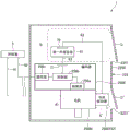
Fig. 1 is a side view showing a robot system according to a first embodiment.
Fig. 2 is a functional block diagram of the robotic system shown in fig. 1.
Fig. 3 is a partial enlarged view of the functional block diagram shown in fig. 2.
Fig. 4 is a functional block diagram showing an example of a control substrate in which the first external device shown in fig. 3 is a pressure detecting section that controls a pressure sensor.
Fig. 5 is a functional block diagram showing a robot system according to a first modification of the first embodiment.
Fig. 6 is a partial enlarged view showing a functional block diagram of a robot system according to a second modification of the first embodiment.
Fig. 7 is a partial enlarged view showing a functional block diagram of a robot system according to a third modification of the first embodiment.
Fig. 8 is a partial enlarged view showing a functional block diagram of the robot system according to the second embodiment.
Fig. 9 is an overall view showing a functional block diagram of the robot system according to the second embodiment.
Fig. 10 is a side view showing a robot according to a third embodiment.
Description of the reference numerals
A robot system 1, a robot 2, a controller 5, a hub device 8, a robot 20, a base 21, a robot arm 22, an end effector 24, a power line 41A, a first communication line 42, a second communication line 43, a branch communication line 45, a first external device 61, a second external device 62, a first device connection portion 71, a second device connection portion 72, a third device connection portion 73, an arm 221, an arm 222, an arm 223, an arm 224, an arm 225, an arm 226, an arm 251 driving device 251D motor driver 251E encoder, a 251M motor, a 252 driving device 252D motor driver 252E encoder 252M motor 253 driving device, 253D motor driver, 253E encoder, 253M motor, 254 driving device, 254D motor driver, 254E encoder, 254M motor, 255 driving device, 255D motor driver, 255E encoder, 255M motor, 256 driving device, 256D motor driver, 256E encoder, 256M motor, 256a detecting portion, 256b controlling portion, 256c communication portion, 610 wiring, 611 pressure detecting portion, 2250 housing, 2251 opening portion, 2251' opening portion, D gate, D ' gate, O1 first shaft, O2 second shaft, O3 third shaft, O4 fourth shaft, O5 fifth shaft, O6 sixth shaft, S internal space, S ' internal space.
Detailed Description
Hereinafter, preferred embodiments of the robot system and the robot according to the present invention will be described in detail with reference to the accompanying drawings.
First embodiment
First, a robot system according to a first embodiment will be described.
Fig. 1 is a side view showing a robot system according to a first embodiment. Fig. 2 is a functional block diagram of the robotic system shown in fig. 1.
The robot system 1 shown in fig. 1 includes a robot 2 and a controller 5 for controlling the operation of the robot 2. The application of the robot system 1 is not particularly limited, and examples thereof include material supply, material removal, conveyance, assembly, and the like for objects such as precision equipment and components constituting the same.
The robot 2 shown in fig. 1 includes a base 21 and a robot arm 22 rotatably coupled to the base 21.
The base 21 is fixed to a floor, a wall, a ceiling, a movable carriage, or other installed part, for example.
The robot arm 22 includes an arm 221 rotatably coupled to the base 21 about a first axis O1, an arm 222 rotatably coupled to the arm 221 about a second axis O2, an arm 223 rotatably coupled to the arm 222 about a third axis O3, an arm 224 rotatably coupled to the arm 223 about a fourth axis O4, an arm 225 rotatably coupled to the arm 224 about a fifth axis O5, and an arm 226 rotatably coupled to the arm 225 about a sixth axis O6. The end effector 24 corresponding to the work to be performed by the robot 2 is attached to the arm 226.
Note that the robot 2 is not limited to the configuration of the present embodiment, and the number of arms included in the robot arm 22 may be 1 to 5 or 7 or more, for example. For example, the robot 2 may be a SCARA robot or a double-arm robot having 2 arms 22.
The robot 2 further includes: a drive 251 for rotating arm 221 relative to base 21, a drive 252 for rotating arm 222 relative to arm 221, a drive 253 for rotating arm 223 relative to arm 222, a drive 254 for rotating arm 224 relative to arm 223, a drive 255 for rotating arm 225 relative to arm 224, and a drive 256 for rotating arm 226 relative to arm 225.
The controller 5 controls the operations of the driving devices 251 to 256 independently so that the arms 221 to 226 are positioned at the target positions. The controller 5 is configured by, for example, a computer, and has a processor (CPU) that processes information, a memory communicably connected to the processor, and an external interface. Various programs executable by the processor are stored in the memory, and the processor can read and execute the various programs stored in the memory.
The driving device 251 is provided inside the base 21, and has a motor 251M as a driving source and an encoder 251E that detects the rotation amount of the motor 251M. The driving device 252 is provided inside the arm 221, and includes a motor 252M as a driving source and an encoder 252E for detecting the rotation amount of the motor 252M. The driving device 253 is provided inside the arm 222, and has a motor 253M as a driving source and an encoder 253E that detects the rotation amount of the motor 253M. The driving device 254 is provided inside the arm 223, and has a motor 254M as a driving source and an encoder 254E that detects the rotation amount of the motor 254M. The driving device 255 is provided inside the arm 224, and has a motor 255M as a driving source and an encoder 255E that detects the rotation amount of the motor 255M. The driving device 256 is provided inside the arm 225, and includes a motor 256M as a driving source and an encoder 256E for detecting the rotation amount of the motor 256M.
The motors 251M to 256M are connected to the controller 5 via power lines 41 for supplying power to the motors 251M to 256M, respectively. The controller 5 supplies electric power to the motors 251M to 256M, and controls driving of the motors 251M to 256M.
On the other hand, the encoders 251E to 256E are connected to the controller 5 via the first communication line 42. This enables communication between the encoders 251E to 256E and the controller 5. The first communication line 42 is a so-called bus type wiring. The bus type wiring in this case is a wiring pattern laid from the main line branch to each of the connection targets in the connection between the controller 5 and the plurality of connection targets, i.e., the encoders 251E to 256E. In the bus-type wiring, the controller 5 and the encoders 251E to 256E do not need to be directly connected to each other as in the star-type wiring, that is, wiring formed by radially laying out the plurality of connection objects from the controller 5. Therefore, the number of first communication lines 42 passing through the inside of the robot arm 22 can be reduced as compared with the star wiring.
The robot system 1 according to the present embodiment further includes a first external device 61 and a second external device 62 provided inside the arm 225. The first external device 61 and the second external device 62 are devices added to the encoder 256E, respectively. That is, the first external device 61 and the second external device 62 may be attached to the robot system 1 in advance, or may be attached later. Hereinafter, the driving device 256 and the first and second external devices 61 and 62 will be described in detail.
Fig. 3 is a partial enlarged view of the functional block diagram shown in fig. 2. Note that, a structure not shown in fig. 2 is added to fig. 3.
The drive 256 shown in fig. 3 is disposed within the arm 225 between the arms 224 and 226 and has a motor 256M and an encoder 256E as previously described. The encoder 256E includes a detecting unit 256a that detects the rotation amount of the motor 256M, a control unit 256b that controls the operation of the detecting unit 256a, and a communication unit 256c that is connected to the control unit 256b and communicates with the controller 5.
The detection unit 256a includes, for example, a scale not shown connected to the rotation shaft of the motor 256M and an optical element not shown for reading the rotation of the scale, and outputs a signal corresponding to the rotation amount of the scale to the control unit 256b. The detection method in the detection unit 256a is not particularly limited.
The control unit 256b receives the signal output from the detection unit 256a, and calculates the rotation amount of the motor 256M. Then, the data of the rotation amount is transmitted to the controller 5 via the communication unit 256c.
The communication unit 256c is interposed between the control unit 256b and the controller 5. The communication unit 256c receives the data of the rotation amount output from the control unit 256b, and converts the data into a signal according to a communication scheme applied to the first communication line 42. Then, the communication unit 256c transmits the converted signal to the controller 5 via the first communication line 42. The communication unit 256c receives a signal including a command to control the control unit 256b, which is transmitted from the controller 5, and outputs the signal to the control unit 256b.
The communication method between the communication unit 256c and the controller 5 includes, for example, serial communication and parallel communication. Among them, serial communication is preferably used. In the serial communication, data can be transmitted and received in a time-division manner, and therefore the number of first communication lines 42 can be reduced. Note that the serial communication may be synchronous communication or asynchronous communication.
Note that an unique ID (identification number) is assigned in advance to the encoder 256E. In this way, at the time of communication, since the transmission destination of data can be specified, even with bus-type wiring, communication can be performed solely between the encoder 256E and the controller 5.
In addition, the encoder 256E also has a first device connection portion 71 for connecting the first external device 61. The first device connection unit 71 is connected to the control unit 256b, and is a port for connecting to the first external device 61. Further, the first device connection portion 71 is connected to the first external device 61 via the second communication line 43.
The first device connection unit 71 includes, for example, a connector, a wiring, a wireless communicator, and the like. Among them, the first device connection portion 71 is preferably a connector or a wiring. Since the connection by the connector and the connection by the wiring are relatively easy to be attached and detached, the connection and disconnection of the second communication line 43 can be easily performed. Therefore, the addition work of the first external device 61 can be efficiently performed. In addition, the wire-based connection is also useful from the viewpoint of noise immunity and reliability.
When the first device connection portion 71 is a connector, the first device connection portion 71 may be, for example, a board mounted connector disposed on a wiring board, not shown, on which the control portion 256b is mounted. Specifically, a parallel connection type connector, a vertical connection type connector, a horizontal connection type connector, a floating connector, and the like are cited. In addition to this, a USB (Universal Serial Bus ) connector, an RS-232C connector, or the like is also possible.
On the other hand, when the first device connection portion 71 is a wiring, the first device connection portion 71 may be configured by, for example, connecting one end of the wiring to a wiring board, not shown, on which the control portion 256b is mounted, and forming the other end of the wiring to be a free end. It should be noted that various connectors may be mounted on one end of the wiring as well as the other end.
The first device connection unit 71 superimposes communication performed between the first external device 61 and the controller 5 on communication on the first communication line 42 via the control unit 256b and the communication unit 256c. That is, the encoder 256E according to the present embodiment has a function of inserting communication between the first external device 61 and the controller 5 into communication between the communication unit 256c and the controller 5 via the first communication line 42. Thereby, it is not necessary to provide a communication line directly connecting between the first external device 61 and the controller 5. Therefore, even if the first external device 61 is added, the number of communication lines laid inside the robot arm 22 does not need to be increased. As a result, the robot system 1 can be prevented from being restricted in design, that is, from being degraded in design freedom.
Specifically, between the communication unit 256c and the controller 5, the data received by the control unit 256b from the detection unit 256a is transmitted to the controller 5 at any time, and a command for controlling the operation of the detection unit 256a is transmitted to the control unit 256b at any time. However, since the capacity of information such as data and commands is not so large, there is a relatively large margin in the communication band.
Then, in the encoder 256E according to the present embodiment, information related to the first external device 61 is inserted in the space for transmitting/receiving information related to the detection unit 256 a. Thus, the first communication line 42 is used not only for communication between the encoder 256E and the controller 5, but also for communication between the first external device 61 and the controller 5. As a result, the first external device 61 can communicate with the controller 5 without increasing the number of the first communication lines 42, and therefore, the degree of freedom in design of the robot system 1 due to the addition of the first external device 61 and the second external device 62 can be prevented from being reduced.
As the first external device 61 that can be added in this way, for example, a control device that controls an end effector such as a gripper, a suction pad, a dispenser, a control device that controls a sensor such as a force sensor, a pressure sensor, a magnetic encoder, and the like can be cited. Examples of the modes of the control devices include a function expansion board having a wiring board and electronic components mounted on the wiring board. Accordingly, a space for disposing such a control device such as a function expansion board, for example, a board mounting rack, a board fixing metal fitting, or the like may be prepared in advance inside the arm 225.
Here, fig. 4 is a functional block diagram showing an example of a control board for controlling the pressure detecting section 611 of the pressure sensor by the first external device 61 shown in fig. 3. Note that in fig. 4, the second external device 62 is omitted from illustration for convenience of illustration.
The robot system 1 shown in fig. 4 further has 2 pressure detection sections 611 provided between the end effector 24 and the arm 226, and wiring 610 connecting the pressure detection sections 611 and the first external device 61. The pressure detection portion 611 includes, for example, an elastic body whose resistance changes when pressure is applied. Therefore, if an external force is applied to the end effector 24, the external force is also applied to the pressure detecting portion 611, and is detected as a change in resistance in the first external device 61. Therefore, the pressure detecting unit 611, the wiring 610, and the first external device 61 function as a pressure sensor.
When such a pressure sensor is added to the robot system 1, the first external device 61 and the controller 5 are not directly connected, but in the present embodiment, the first external device 61 and the first device connection unit 71 may be connected. This shortens the extension of the second communication line 43, simplifies the extension work, and prevents the degree of freedom in design of the robot system 1 from being lowered due to the extension.
In the case where the first external device 61 is a circuit board such as a function expansion board, the second communication line 43 does not need to be a flexible long wire or the like, and may be a terminal or the like provided in the board-to-board connector, for example.
Further, in the case where the first device connection unit 71 is a wireless communicator, a wireless communicator conforming to a communication standard such as Bluetooth (registered trademark), wireless LAN (Local Area Network ) or the like may be used. Thereby, the second communication line 43 can be made wireless.
As a communication method for the second communication line 43, for example, serial communication or parallel communication is cited, but serial communication is preferably used. In the serial communication, since data can be transmitted and received in a time-division manner, even when the number of additional external devices is increased, it is not necessary to significantly increase the number of second communication lines 43. Therefore, the wiring work of the second communication line 43 is made easy, and the space required for the wiring of the second communication line 43 can be saved.
Note that the communication scheme for the second communication line 43 may be the same as or different from that for the first communication line 42 described above. The serial communication may be synchronous communication or asynchronous communication.
In addition, the first external device 61 has a second device connection portion 72 for connecting the second external device 62. The second device connection section 72 is a port for connecting the second external device 62, and is connected to the second external device 62 via the second communication line 43.
The configuration of the second device connecting portion 72 is appropriately selected from the configurations listed as the configuration of the first device connecting portion 71, and may be the same as or different from the configuration of the first device connecting portion 71.
The second external device 62 is also appropriately selected from the devices listed as the first external device 61. Further, the second external device 62 shown in fig. 3 has a third device connection section 73 for connection with other external devices not shown. The third device connection unit 73 is a port to which other external devices are connected, and can be connected to other external devices via a communication line, not shown.
As described above, the robot system 1 according to the present embodiment includes the robot 2, the controller 5 that controls the operation of the robot 2, and the first external device 61. Further, the robot 2 includes: an arm 225 as a first member; an arm 226 as a second member that rotates with respect to the arm 225; a motor 256M that generates a driving force for rotating the arm 226 relative to the arm 225; the encoder 256E includes a detecting unit 256a that detects the rotation amount of the motor 256M, a control unit 256b that controls the operation of the detecting unit 256a, a communication unit 256c that communicates with the controller 5, and a first device connection unit 71 that is connected to the first external device 61, and the control unit 256b is connected to the detecting unit 256a, the communication unit 256c, and the first device connection unit 71; and a first communication line 42 connecting the communication unit 256c and the controller 5, the data of the first external device 61 being transmitted to the controller 5 via the first device connection unit 71 and the first communication line 42.
According to the robot system 1 described above, the encoder 256E has a function of causing the communication between the first external device 61 and the controller 5 to be inserted into the communication between the communication section 256c and the controller 5 via the first communication line 42 via the control section 256b. Thereby, it is not necessary to provide a communication line directly connecting between the first external device 61 and the controller 5. As a result, even if the first external device 61 is added, the number of communication lines laid inside the robot arm 22 does not need to be increased, and therefore, the communication lines occupy a small volume, and accordingly, the degree of freedom in design of the robot system 1 can be prevented from being reduced.
The robot system 1 according to the present embodiment further includes a second external device 62 and a second device connection unit 72 connected to the second external device 62. In the present embodiment, the encoder 256E is connected to the first external device 61 and the second external device 62 via the second communication line 43 that forms a bus-type wiring.
Specifically, in fig. 3, the first device connection portion 71 and the first external device 61 are connected via the second communication line 43, and the second device connection portion 72 and the second external device 62 are connected via the second communication line 43. Therefore, the wiring is so-called daisy-chain wiring in appearance. On the other hand, the bus type wiring is electrically connected by a main line extending from the first device connection portion 71 and branch lines branching from the main line to the first external device 61 and the second external device 62, respectively.
Such bus-type wiring facilitates arbitrary addition of external devices. That is, if the bus type wiring is used, the second external device 62 can be added without adding other device connection parts other than the first device connection part 71 to a wiring board or the like, not shown, on which the control part 256b is mounted. Therefore, no structural change of the wiring board or the like is required regardless of the number of additional external devices. Therefore, the addition work can be performed more simply. Further, the wiring board on which the control unit 256b is mounted can be prevented from being enlarged. As a result, the robot system 1 can be realized in which the robot arm 22 can be prevented from being increased in size and weight due to the addition of external devices.
Note that, unique IDs (identification numbers) are assigned in advance to the first external device 61 and the second external device 62, respectively. In this way, at the time of communication, since the transmission destination of data can be specified, even with bus-type wiring, communication can be performed individually between each external device and the control unit 256b and between each external device and the controller 5.
As described above, the second device connection unit 72 shown in fig. 3 is provided in the first external device 61. As a result, in fig. 3, the daisy-chain wiring can be used in the external appearance, and the connection operation between the second device connection unit 72 and the second external device 62 can be performed electrically as the bus-type wiring. As a result, even when the number of external devices to be added increases, the robot system 1 in which the external devices are easily added can be realized.
In addition, the arm 225 shown in fig. 3 has a housing 2250. The driving device 256, the first external device 61, and the second external device 62 are housed inside the housing 2250. Further, the housing 2250 also has an opening 2251 that enables access to the interior. The opening 2251 is closed by a door D that enables a portion of the housing 2250 to be opened or closed. When the door D is opened, the internal space S shown in fig. 3 can be easily accessed from the outside. Accordingly, when the first and second external devices 61 and 62 are provided in the internal space S, the first and second external devices 61 and 62 can be added without detaching the housing 2250. Therefore, the addition work can be performed more simply.
In other words, the encoder 256E is provided in the housing 2250, and the opening 2251 is provided at a position corresponding to the first device connection portion 71. This makes it possible to easily perform a work of connecting or disconnecting the second communication line 43 to or from the first device connection portion 71 from the outside of the housing 2250. Note that the position corresponding to the first device connection portion 71 refers to a position at which wiring work can be performed on the first device connection portion 71 from outside the housing 2250 via the opening 2251.
The robot system 1 may have at least the first device connection unit 71 to which the first external device 61 can be added and the first external device 61, and thus it is not necessary to have the second external device 62. The number of external devices that can be added is not limited to 2, but may be 1, or 3 or more.
In the above description, the arm 225 is described as "the first member" and the arm 226 is described as "the second member which rotates with respect to the first member", but the first member and the second member are not limited thereto. In the case of the present embodiment, the base 21 and the arms 221 to 225 can be used as the first member. In addition, the arms 221 to 226 adjacent to the first member may each be a second member.
Further, it is not necessary to provide both the first external device 61 and the second external device 62 in the housing 2250, and at least one of them may be provided outside the housing 2250. For example, when the first external device 61 is provided outside, the first device connection portion 71 may be provided at a position exposed to the outside of the housing 2250.
First modification example
Here, a first modification of the first embodiment will be described.
Fig. 5 is a functional block diagram showing a robot system according to a first modification of the first embodiment.
In the following, a first modification will be described, but in the following, the differences from the first embodiment will be described, and for the same matters, the description thereof will be omitted. Note that in fig. 5, the same reference numerals are given to the same structures as those of the first embodiment.
The robot system 1 shown in fig. 5 further has a branch communication line 45 connecting the first external device 61 and the first communication line 42. That is, the first external device 61 is connected to the branch communication line 45 branched from the first communication line 42. Thus, the first external device 61 can communicate not only via the second communication line 43 and the first communication line 42, but also via the branch communication line 45 and the first communication line 42. Thus, redundancy can be provided for communication. That is, even when the first device connection unit 71 and the second communication line 43 fail, communication between the first external device 61 and the controller 5 can be ensured. It is noted that the branch communication line 45 may also be connected to the second external device 62.
In the robot system 1, it is also conceivable to add the first external device 61 and the second external device 62 and provide the branch communication line 45 in advance.
Second modification example
Next, a robot system according to a second modification of the first embodiment will be described.
Fig. 6 is a partial enlarged view showing a functional block diagram of a robot system according to a second modification of the first embodiment.
In the following, a second modification will be described, but in the following, the differences from the first embodiment will be described, and for the same matters, the description thereof will be omitted. Note that in fig. 6, the same reference numerals are given to the same structures as those of the first embodiment.
In the first embodiment described above, the second communication lines 43 constitute bus-type wirings, but in the present second modification, the second communication lines 43 constitute star-type wirings. That is, the robot system 1 according to the second modification example further includes the second external device 62. The encoder 256E of the robot system 1 according to the second modification also includes a second device connection unit 72 to which the second external device 62 is connected. The second device connection unit 72 is included in the encoder 256E, and is connected to the control unit 256b. The encoder 256E is connected to the first external device 61 and the second external device 62 via the second communication line 43 that forms a star-shaped wiring.
Specifically, the encoder 256E according to the second modification example further includes a second device connection unit 72 connected to the control unit 256b in parallel with the first device connection unit 71. Further, the second external device 62 is connected to the second device connection section 72 via the second communication line 43. This enables the plurality of second communication lines 43 to be juxtaposed. Therefore, even when the communication capacity of the second communication line 43 is small or when the capacity of the data transmitted and received by the first external device 61 and the second external device 62 is large, the external device can be added.
Third modification example
Next, a robot system according to a third modification of the first embodiment will be described.
Fig. 7 is a partial enlarged view showing a functional block diagram of a robot system according to a third modification of the first embodiment.
In the following, a third modification will be described, but in the following, the differences from the first embodiment will be described, and for the same matters, the description thereof will be omitted. Note that in fig. 7, the same reference numerals are given to the same structures as those in the first embodiment.
The robot system 1 according to the third modification example includes a hub device 8 provided in a housing 2250. The hub device 8 is a branching device that branches the second communication line 43 into a plurality of branches. The first external device 61 and the second external device 62 are connected to the branched second communication line 43. By using such a hub device 8, the addition work can be performed more simply.
Second embodiment
Next, a robot system according to a second embodiment will be described.
Fig. 8 is a partial enlarged view showing a functional block diagram of the robot system according to the second embodiment. Fig. 9 is an overall view showing a functional block diagram of the robot system according to the second embodiment.
In the following, the second embodiment will be described, but in the following, the differences from the first embodiment will be described, and for the same matters, the description thereof will be omitted. Note that in fig. 8 and 9, the same reference numerals are given to the same components as those in the first embodiment.
As shown in fig. 8, the robot system 1 according to the second embodiment has a motor driver 256D as the second external device 62 provided to the housing 2250. The motor driver 256D controls the current applied to the motor 256M by a driving method such as rectangular wave driving in which the current flows in a rectangular waveform, sinusoidal wave driving in which the current flows in a sinusoidal waveform, or the like. By providing such a motor driver 256D for the motor 256M, the power supply line 41 constituting the star wiring as described in the first embodiment can be changed to the power supply line 41A constituting the bus wiring as shown in fig. 9. As a result, the number of power lines 41A passing through the inside of the robot arm 22 shown in fig. 1 can be reduced, and the degree of freedom in design of the robot system 1 can be improved.
In the present embodiment, the same devices as the motor driver 256D as the external devices are provided for the motors 251M to 256M, respectively. Specifically, the robot system 1 shown in fig. 9 further includes a motor driver 251D provided to the motor 251M provided to the driving device 251, a motor driver 252D provided to the motor 252M provided to the driving device 252, a motor driver 253D provided to the motor 253M provided to the driving device 253, a motor driver 254D provided to the motor 254M provided to the driving device 254, a motor driver 255D provided to the motor 255M provided to the driving device 255, and a motor driver 256D provided to the motor 256M provided to the driving device 256. By providing such motor drivers 251D to 256D individually, even in the case where the power supply line 41A constituting the bus-type wiring is used by being able to apply a common dc voltage to the motor drivers 251D to 256D, the driving of the motors 251M to 256M can be controlled individually.
Further, in the robot system 1 shown in fig. 9, the motor drivers 251D to 255D correspond to the first external device 61 added to the encoders 251E to 255E, and the motor driver 256D corresponds to the second external device 62 added to the encoder 256E. By providing the motor drivers 251D to 256D as the first external device 61 or the second external device 62 in this way, communication between the motor drivers 251D to 256D and the controller 5 can be superimposed on communication in the first communication line 42. Thus, since it is not necessary to provide communication lines directly connecting the motor drivers 251D to 256D and the controller 5, the number of communication lines laid inside the robot arm 22 does not need to be increased.
In addition, as shown in fig. 8, the housing 2250 further has an opening 2251 'that enables access to the interior space S' in which the motor driver 256D is located. The opening 2251 'is closed by a door D' that enables a portion of the housing 2250 to be opened or closed. When the door D 'is opened, the internal space S' shown in fig. 8 can be easily accessed from the outside.
Third embodiment
Next, a robot according to a third embodiment will be described.
Fig. 10 is a side view showing a robot according to a third embodiment.
In the following, the third embodiment will be described, but in the following, the differences from the first embodiment will be described, and for the same matters, the description thereof will be omitted. Note that in fig. 10, the same reference numerals are given to the same structures as those of the first embodiment.
The robot 20 according to the third embodiment is similar to the robot system 1 according to the first embodiment, except that the controller 5 for controlling the driving of the robot is incorporated in the base 21. That is, the robot system 1 according to the first embodiment is provided with the controller 5 outside the housing of the robot 2, and the robot 20 according to the present embodiment has the controller 5 inside. Thus, the robot 20 can control its own drive.
The robot 20 according to the present embodiment also includes a base 21 and a robot arm 22, and has the same configuration as the robot system 1 according to the first embodiment.
That is, the robot 20 according to the present embodiment includes, like the robot system 1 shown in fig. 1 to 3: a controller 5; a first external device 61; an arm 225 as a first member; an arm 226 as a second member that rotates with respect to the arm 225; a motor 256M that generates a driving force for rotating the arm 226 relative to the arm 225; the encoder 256E includes a detecting unit 256a that detects the rotation amount of the motor 256M, a control unit 256b that controls the operation of the detecting unit 256a, a communication unit 256c that communicates with the controller 5, and a first device connection unit 71 that is connected to the first external device 61, and as shown in fig. 3, the control unit 256b is connected to the detecting unit 256a, the communication unit 256c, and the first device connection unit 71; and a first communication line 42 connecting the communication unit 256c and the controller 5, the data of the first external device 61 being transmitted to the controller 5 via the first device connection unit 71 and the first communication line 42.
According to the robot 20 described above, the encoder 256E has a function of causing the communication between the first external device 61 and the controller 5 to be inserted into the communication between the communication section 256c and the controller 5 via the first communication line 42 via the control section 256b shown in fig. 3. Thereby, it is not necessary to provide a communication line directly connecting between the first external device 61 and the controller 5. As a result, even if the first external device 61 is added, the number of communication lines laid inside the robot arm 22 does not need to be increased, and therefore, the degree of freedom in design of the robot 20 can be prevented from being reduced.
The robot system and the robot according to the present invention have been described above based on the illustrated embodiments, but the present invention is not limited to this, and the configuration of each part may be replaced with any configuration having the same function. In the above embodiment, any other structure may be added. Furthermore, 2 of the foregoing embodiments may be combined.
Claims (4)
1. A robot system is provided with a robot, a controller for controlling the operation of the robot, and a first external device,
the robot has:
a first component;
a second member that rotates relative to the first member;
a motor that generates a driving force for rotating the second member with respect to the first member;
an encoder including a detection unit that detects a rotation amount of the motor, a control unit that controls an operation of the detection unit, a communication unit that communicates with the controller, and a first device connection unit that is connected to the first external device, the control unit being connected to the detection unit, the communication unit, and the first device connection unit; and
a first communication line connecting the communication unit and the controller,
the data of the first external device is transmitted to the controller via the first device connection portion and the first communication line;
the robot system further includes:
a second external device; and
a second device connection part connected with the second external device,
the encoder is connected to the first external device and the second external device through bus-type wiring;
the second device connection portion is provided to the first external device.
2. The robotic system as set forth in claim 1 wherein,
the first external device is connected to a branch communication line branched from the first communication line.
3. The robotic system as set forth in claim 1 wherein,
the communication mode between the communication part and the controller is serial communication.
4. A robot is characterized by comprising:
a controller;
a first external device;
a first component;
a second member that rotates relative to the first member;
a motor that generates a driving force for rotating the second member with respect to the first member;
an encoder including a detection unit that detects a rotation amount of the motor, a control unit that controls an operation of the detection unit, a communication unit that communicates with the controller, and a first device connection unit that is connected to the first external device, the control unit being connected to the detection unit, the communication unit, and the first device connection unit; and
a first communication line connecting the communication unit and the controller,
the data of the first external device is transmitted to the controller via the first device connection portion and the first communication line;
the robot further includes:
a second external device; and
a second device connection part connected with the second external device,
the encoder is connected to the first external device and the second external device through bus-type wiring;
the second device connection portion is provided to the first external device.
Applications Claiming Priority (2)
| Application Number | Priority Date | Filing Date | Title |
|---|---|---|---|
| JP2019057446A JP7318257B2 (en) | 2019-03-25 | 2019-03-25 | Robotic systems and robots |
| JP2019-057446 | 2019-03-25 |
Publications (2)
| Publication Number | Publication Date |
|---|---|
| CN111730590A CN111730590A (en) | 2020-10-02 |
| CN111730590B true CN111730590B (en) | 2023-06-27 |
Family
ID=72606891
Family Applications (1)
| Application Number | Title | Priority Date | Filing Date |
|---|---|---|---|
| CN202010200638.5A Active CN111730590B (en) | 2019-03-25 | 2020-03-20 | Robot system and robot |
Country Status (3)
| Country | Link |
|---|---|
| US (1) | US11628579B2 (en) |
| JP (1) | JP7318257B2 (en) |
| CN (1) | CN111730590B (en) |
Families Citing this family (3)
| Publication number | Priority date | Publication date | Assignee | Title |
|---|---|---|---|---|
| JP7451889B2 (en) * | 2019-06-27 | 2024-03-19 | セイコーエプソン株式会社 | robot |
| JPWO2023275966A1 (en) * | 2021-06-29 | 2023-01-05 | ||
| US20230150120A1 (en) * | 2021-11-17 | 2023-05-18 | Kawasaki Jukogyo Kabushiki Kaisha | Substrate Conveying Robot and Substrate Conveying Robot System |
Citations (8)
| Publication number | Priority date | Publication date | Assignee | Title |
|---|---|---|---|---|
| CN103302673A (en) * | 2013-05-17 | 2013-09-18 | 东莞市伯朗特自动化科技有限公司 | Control method and system for automated manipulator arm |
| CN103963075A (en) * | 2013-01-28 | 2014-08-06 | 株式会社安川电机 | Robot system |
| JP2014188641A (en) * | 2013-03-28 | 2014-10-06 | Seiko Epson Corp | Robot |
| CN105547141A (en) * | 2014-10-27 | 2016-05-04 | 精工爱普生株式会社 | Position detecting device, electronic apparatus, recording apparatus, robot, and position detecting method |
| CN105818160A (en) * | 2015-01-08 | 2016-08-03 | 中国科学院上海微系统与信息技术研究所 | Universal robot joints and robot arm |
| JP2017030069A (en) * | 2015-07-30 | 2017-02-09 | セイコーエプソン株式会社 | Robot control system, robot, and robot system |
| CN107436159A (en) * | 2016-05-17 | 2017-12-05 | 康茂股份公司 | Sensorised covering for commercial plant |
| CN108687795A (en) * | 2017-03-30 | 2018-10-23 | 精工爱普生株式会社 | Robot |
Family Cites Families (6)
| Publication number | Priority date | Publication date | Assignee | Title |
|---|---|---|---|---|
| JPS63298403A (en) | 1987-05-28 | 1988-12-06 | Fanuc Ltd | Data transmission system for numerical controller |
| JPH05266391A (en) * | 1992-03-17 | 1993-10-15 | Matsushita Electric Ind Co Ltd | Robot device |
| JP4191437B2 (en) | 2002-06-26 | 2008-12-03 | 並木精密宝石株式会社 | Board-integrated brushless motor |
| US8204244B2 (en) | 2008-09-24 | 2012-06-19 | Bose Corporation | Spare tire cover-mounted loudspeaker |
| JP5675401B2 (en) | 2011-02-07 | 2015-02-25 | キヤノン株式会社 | manipulator |
| JP6416983B1 (en) | 2017-05-22 | 2018-10-31 | ファナック株式会社 | Rotation axis angle calibration method and angle calibration program |
-
2019
- 2019-03-25 JP JP2019057446A patent/JP7318257B2/en active Active
-
2020
- 2020-03-20 CN CN202010200638.5A patent/CN111730590B/en active Active
- 2020-03-24 US US16/827,811 patent/US11628579B2/en active Active
Patent Citations (8)
| Publication number | Priority date | Publication date | Assignee | Title |
|---|---|---|---|---|
| CN103963075A (en) * | 2013-01-28 | 2014-08-06 | 株式会社安川电机 | Robot system |
| JP2014188641A (en) * | 2013-03-28 | 2014-10-06 | Seiko Epson Corp | Robot |
| CN103302673A (en) * | 2013-05-17 | 2013-09-18 | 东莞市伯朗特自动化科技有限公司 | Control method and system for automated manipulator arm |
| CN105547141A (en) * | 2014-10-27 | 2016-05-04 | 精工爱普生株式会社 | Position detecting device, electronic apparatus, recording apparatus, robot, and position detecting method |
| CN105818160A (en) * | 2015-01-08 | 2016-08-03 | 中国科学院上海微系统与信息技术研究所 | Universal robot joints and robot arm |
| JP2017030069A (en) * | 2015-07-30 | 2017-02-09 | セイコーエプソン株式会社 | Robot control system, robot, and robot system |
| CN107436159A (en) * | 2016-05-17 | 2017-12-05 | 康茂股份公司 | Sensorised covering for commercial plant |
| CN108687795A (en) * | 2017-03-30 | 2018-10-23 | 精工爱普生株式会社 | Robot |
Also Published As
| Publication number | Publication date |
|---|---|
| JP7318257B2 (en) | 2023-08-01 |
| US11628579B2 (en) | 2023-04-18 |
| CN111730590A (en) | 2020-10-02 |
| JP2020157401A (en) | 2020-10-01 |
| US20200307000A1 (en) | 2020-10-01 |
Similar Documents
| Publication | Publication Date | Title |
|---|---|---|
| CN111730590B (en) | Robot system and robot | |
| US11175131B2 (en) | Self-configuring component identification and signal processing system for a coordinate measurement machine | |
| EP1793292A1 (en) | Robot controller system | |
| US11108305B2 (en) | Drive device | |
| US20060106492A1 (en) | Multi-axis robot provided with a control system | |
| AU768418B2 (en) | System and method for carrying out an electronic control or regulation | |
| US10795849B2 (en) | System of automation components and method for operating the same | |
| CN113246876B (en) | Communication system and proxy input and output unit | |
| JP3186490B2 (en) | Multiplex encoder | |
| US20110295428A1 (en) | Machine motion control system | |
| JP2012141736A (en) | Serial transmission system and slave unit suitable for the same | |
| US20040178761A1 (en) | Method of driving a servo motor with a built-in drive circuit | |
| US10515540B2 (en) | Robot | |
| JP7164564B2 (en) | Vacuum system and method for identifying electronic modules within the vacuum system | |
| US20230150120A1 (en) | Substrate Conveying Robot and Substrate Conveying Robot System | |
| EP4318148A1 (en) | Master unit and communication system | |
| US7047342B2 (en) | Data processing structure | |
| CN116963881A (en) | Robot system and method for assembling robot system | |
| CN113273143B (en) | Communication system and connector | |
| US20040014483A1 (en) | Maintenance system for control devices of hydrostatic drives | |
| JP4198576B2 (en) | Incorrect connection detection system | |
| JP2611124B2 (en) | Encoder system | |
| KR102609770B1 (en) | An External Connector for Home Appliances | |
| KR102317058B1 (en) | Motion sensor network system | |
| EP4318150A1 (en) | I/o unit and communication system |
Legal Events
| Date | Code | Title | Description |
|---|---|---|---|
| PB01 | Publication | ||
| PB01 | Publication | ||
| SE01 | Entry into force of request for substantive examination | ||
| SE01 | Entry into force of request for substantive examination | ||
| GR01 | Patent grant | ||
| GR01 | Patent grant |