CN1113427C - Gel-filled closure - Google Patents
Gel-filled closure Download PDFInfo
- Publication number
- CN1113427C CN1113427C CN96199247A CN96199247A CN1113427C CN 1113427 C CN1113427 C CN 1113427C CN 96199247 A CN96199247 A CN 96199247A CN 96199247 A CN96199247 A CN 96199247A CN 1113427 C CN1113427 C CN 1113427C
- Authority
- CN
- China
- Prior art keywords
- gel
- cavity
- hinge
- box
- filled
- Prior art date
- Legal status (The legal status is an assumption and is not a legal conclusion. Google has not performed a legal analysis and makes no representation as to the accuracy of the status listed.)
- Expired - Lifetime
Links
Images


Classifications
-
- H—ELECTRICITY
- H02—GENERATION; CONVERSION OR DISTRIBUTION OF ELECTRIC POWER
- H02G—INSTALLATION OF ELECTRIC CABLES OR LINES, OR OF COMBINED OPTICAL AND ELECTRIC CABLES OR LINES
- H02G15/00—Cable fittings
- H02G15/08—Cable junctions
- H02G15/10—Cable junctions protected by boxes, e.g. by distribution, connection or junction boxes
- H02G15/113—Boxes split longitudinally in main cable direction
-
- G—PHYSICS
- G02—OPTICS
- G02B—OPTICAL ELEMENTS, SYSTEMS OR APPARATUS
- G02B6/00—Light guides; Structural details of arrangements comprising light guides and other optical elements, e.g. couplings
- G02B6/44—Mechanical structures for providing tensile strength and external protection for fibres, e.g. optical transmission cables
- G02B6/4439—Auxiliary devices
- G02B6/444—Systems or boxes with surplus lengths
- G02B6/4441—Boxes
- G02B6/4446—Cable boxes, e.g. splicing boxes with two or more multi fibre cables
-
- H—ELECTRICITY
- H01—ELECTRIC ELEMENTS
- H01R—ELECTRICALLY-CONDUCTIVE CONNECTIONS; STRUCTURAL ASSOCIATIONS OF A PLURALITY OF MUTUALLY-INSULATED ELECTRICAL CONNECTING ELEMENTS; COUPLING DEVICES; CURRENT COLLECTORS
- H01R4/00—Electrically-conductive connections between two or more conductive members in direct contact, i.e. touching one another; Means for effecting or maintaining such contact; Electrically-conductive connections having two or more spaced connecting locations for conductors and using contact members penetrating insulation
- H01R4/70—Insulation of connections
-
- H—ELECTRICITY
- H02—GENERATION; CONVERSION OR DISTRIBUTION OF ELECTRIC POWER
- H02G—INSTALLATION OF ELECTRIC CABLES OR LINES, OR OF COMBINED OPTICAL AND ELECTRIC CABLES OR LINES
- H02G15/00—Cable fittings
- H02G15/003—Filling materials, e.g. solid or fluid insulation
-
- H—ELECTRICITY
- H02—GENERATION; CONVERSION OR DISTRIBUTION OF ELECTRIC POWER
- H02G—INSTALLATION OF ELECTRIC CABLES OR LINES, OR OF COMBINED OPTICAL AND ELECTRIC CABLES OR LINES
- H02G15/00—Cable fittings
- H02G15/007—Devices for relieving mechanical stress
-
- H—ELECTRICITY
- H02—GENERATION; CONVERSION OR DISTRIBUTION OF ELECTRIC POWER
- H02G—INSTALLATION OF ELECTRIC CABLES OR LINES, OR OF COMBINED OPTICAL AND ELECTRIC CABLES OR LINES
- H02G15/00—Cable fittings
- H02G15/08—Cable junctions
- H02G15/18—Cable junctions protected by sleeves, e.g. for communication cable
-
- H—ELECTRICITY
- H01—ELECTRIC ELEMENTS
- H01R—ELECTRICALLY-CONDUCTIVE CONNECTIONS; STRUCTURAL ASSOCIATIONS OF A PLURALITY OF MUTUALLY-INSULATED ELECTRICAL CONNECTING ELEMENTS; COUPLING DEVICES; CURRENT COLLECTORS
- H01R13/00—Details of coupling devices of the kinds covered by groups H01R12/70 or H01R24/00 - H01R33/00
- H01R13/46—Bases; Cases
- H01R13/52—Dustproof, splashproof, drip-proof, waterproof, or flameproof cases
- H01R13/5213—Covers
-
- H—ELECTRICITY
- H01—ELECTRIC ELEMENTS
- H01R—ELECTRICALLY-CONDUCTIVE CONNECTIONS; STRUCTURAL ASSOCIATIONS OF A PLURALITY OF MUTUALLY-INSULATED ELECTRICAL CONNECTING ELEMENTS; COUPLING DEVICES; CURRENT COLLECTORS
- H01R13/00—Details of coupling devices of the kinds covered by groups H01R12/70 or H01R24/00 - H01R33/00
- H01R13/46—Bases; Cases
- H01R13/52—Dustproof, splashproof, drip-proof, waterproof, or flameproof cases
- H01R13/5216—Dustproof, splashproof, drip-proof, waterproof, or flameproof cases characterised by the sealing material, e.g. gels or resins
Abstract
A gel-filled closure (10) for environmentally protecting a connector (40) forming a connection between a cable (41) and at least one electrical component (which may be another cable) (42, 43) is disclosed. The closure includes first and second cavitied bodies (12a, 12b), each having two lateral sides (13) and two end sides (14); a hinge (15) joining the first and second cavitied bodies along a lateral side thereof, such that the cavitied bodies are capable of pivoting around the hinge and closing around the connector and immediately adjacent portions of the cable and the at least one electrical component. A gel (24) substantially fills each of the first and second cavitied bodies. At least one of the cavitied bodies has a flap (16a, 16b) disposed along the lateral edge thereof distal from the hinge, for directing gel flow in the lateral direction as the first and second cavitied bodies are closed. A locking mechanism (19, 20) for securing the cavitied bodies in a closed position is also provided.
Description
TECHNICAL FIELD OF THE INVENTION
The present invention relates to a kind of gel-filled box from the outer protection cable joint.
Background of invention
When linking to each other, generally being its insulation sheath to be peelled off one section the conductor of the inside is exposed so that connect a cable (no matter being used for transmission communication signal or transferring electric power) and other electric component (can be another root cable or the miscellaneous equipment such as switching device or transformer).Concrete operations are with a connector two conductors to be clipped together to realize electrically contacting between it.At this moment be necessary from outer protection joint (conductor that exposes and connector), especially make it be not easy the infringement that is subjected to easily causing short circuit or reduces the moisture of transmission signals quality.
Existing method from the outer protection joint comprises the employing adhesive plaster, and elasticity pushes away and connects box, the heat recovery (or the title pyrocondensation) box, and the mold pressing resin box.Wherein each all has certain defective.Adhesive plaster is difficult to be used for reliably the complicated shape joint as Y connection etc., and twines very and take a lot of work.Use to push away to connect between box requirement cable and this box to be tight fit, the power that for this reason needs is very big and make difficulty is installed.In addition, also may occur leaking, and the shape when being used for Y connection is too complicated.Heat is restored box and is required that specific purpose tool (as blowtorch) is arranged, and this is adventurous under some environment.Simultaneously, also to there be certain skill could guarantee suitable recovery degree and/or avoids overheated.The mold pressing resin box requires at the scene resin to be mixed, injects and solidifies, and this is inconvenient.Need to solidify and to mean that joint is inactive before reaching certain critical curing degree, thereby can't carry out following operation.
People's such as Debbaut U.S. Pat 4,600,261 (1986) (calling " Debbaut ' 261 " in the following text) is thought, being used as encapsulant in the suitable box of the gel of compression injection.Benefit with gel is to encapsulate complex-shaped shapes of substrates easily, and can repeatedly pour into.The shape of box can be various, for example two half hull shapes that separate, elbow-shaped, with gemel half hull shape (also being clamshell shape) and winding escalators (wrap-arounds) etc., these are in the U.S. Pat 5 of the patent WO 95/11543 (1995) of Raychem and Roney etc., in 347,084 (1994) (the calling " Roney ' 084 " in the following text) explanation is arranged all.With gemel gel-filled box has several advantages, as installs simply, need not all can install by any instrument with a hand sometimes; In addition, it can be used for complex-shaped connector and various sizes and configuration cable, comprise Y connection.
Yet gel-filled hinge type box also has some limitation.May make cassette material produce permanent deformation during the gel expanded by heating, thereby make gel interface loosening.It is responsive especially to this problem to be used for the box that power cable connects, because the big electric current of tiding over can make the temperature of gel rise to up to 90 ℃ even 130 ℃.When being contained in joint in the box, it is outer and run off that gel may be extruded box, so that the normal compression of the remaining gel of influence and hinder box normally to lock.The internal pressure that is imposed on box by the gel that compresses forms a moment of torsion, makes the box distortion and retaining mechanism is unclamped.In the mill, usually the hinge type box is kept flat, inject uncured gel in each half shell then and make its curing.At this moment cable to the import of box must be a fluid seal, and this could inject gel in each half shell.Roney ' 084 suggestion adopts the disengaged encapsulation to solve this problem.But, this mounting box period of the day from 11 p.m. to 1 a.m that is encapsulated in is difficult to throw off, and may need to cut with knife, and this will increase extra instrument and step, does not wish certainly to do like this.In addition, in case after throwing off, the loss of gel when this sealing just is difficult to prevent to keep in repair effectively, thereby infringement sealing effect.Consider these problems, we have invented a kind of gel-filled box of modified model as described below.
Summary of the invention
The invention provides a kind of gel-filled box of the joint from outer protection stube cable and at least a electric component, it comprises:
First and second cavitys, each surrounds its inner chamber by two horizontal edges and two sides;
A horizontal edge along the one the second each cavitys is its hinge that links up, and cavity can be around this hinge through and around joint and next-door neighbour's cable section and the sealing of at least one electric component;
Substantially fill with the gel of the one the second each cavitys;
First baffle plate of the upper surface of described horizontal edge is extended and stretches out on a edge on first cavity away from the horizontal edge of this hinge, extend and stretch out the second baffle of the upper surface of described horizontal edge away from the horizontal edge of this hinge with an edge on second cavity, when this first and second cavity is closed, this first and second baffle plate overlaps the covering stream of gel each other, and guiding gel lateral flow; And
Keep cavity to be in the retaining mechanism of closed condition.
In a preferred embodiment, each cavity all is equipped with a baffle plate, that is: first cavity has first baffle plate that install away from the horizontal edge of hinge on an edge, second second baffle that cavity has an edge to install away from the horizontal edge of hinge, two baffle plates overlap joint mutually flows gel along the transverse direction when the one the second cavitys are closed.
In a further preferred embodiment, each bar side comprises a plurality of finger-like sheets that connected together by brittle diaphragm each other.This structure provides a kind of box that has the side of convection cell sealing when injecting the uncured gel that flows, thereby can hold this uncured gel and prevent that it from spilling, simultaneously when box during around cable and the tab closure that is attached thereto, owing to adopting the fragility side to make box be applicable to cables with different diameters.
The accompanying drawing summary
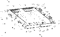
Fig. 1 a and 1b represent two different views of a box of the present invention.
Fig. 2 a and 2b represent the details of a box of the present invention.
Fig. 3 a and 3b represent that box of the present invention covers the installation method of a joint that a cable is linked to each other with the two other cable.
Fig. 4 represents a preferred embodiment of joint.
Preferred embodiment is described
Fig. 1 a and 1b are respectively the top perspective and the bottom perspective view of a gel-filled box 10 of the present invention.Box 10 comprises first and second cavity 12a and the 12b, and each cavity respectively has two horizontal edges 13 and two sides 14, centers on inner chamber 28 by them. Cavity 12a and 12b connect together along a horizontal edge 13 each other by hinge 15.In the preferred version here, hinge 15 is hinges, but also can be other form, as integral hinge or gate-type hinge.The size of cavity 12a and 12b and shape should make its can be when hinge 15 rotates and closes formed enclosure space can hold a joint and with joint near that part of cable and electric component, the latter two connect together by joint, and this will speak of below.Gel 24 is filled with each cavity 12a and 12b basically.Have at least a cavity 12a, 12b upper edge away from the horizontal edge 13 of hinge 15 baffle plate to be housed, this baffle plate reaches the top of cavity always.In the preferred version shown in the figure, a baffle plate is housed all on each cavity 12a and the 12b, on the first cavity 12a is the first baffle plate 16a, and on the second cavity 12b is second baffle 16b.When cavity 12a, 12b solderless wrapped connection head and the cable that is connected by it and electric component sealing, gel 24 beginnings are outwards extruded, and direction is shown in arrow a, b and the c.The gel of extruding along the c direction can influence retaining mechanism (below meeting speak of) and increase the required power of closing.But baffle plate 16a and 16b overlap when box is closed mutually, stop gel to flow along the c direction, and it are mobile towards the direction shown in arrow d and the e to make it change the flow direction.This closes power and improves the transverse sealing quality favourable to minimizing.In illustrated structure, baffle plate 16a rides over the outside of 16b, and a groove 26 is arranged on the cavity 12b, is used for admitting baffle plate 16a.But the mode of overlap joint and the position of groove 26 also can be conversely.Though not really strict to the length requirement of baffle plate 16a and 16b, they should long enough wish the predictive role of the lateral flow of the gel 24 that takes place to play partition.Preferably the total length with horizontal edge 13 is the same basically for the length of two baffle plate 16a, 16b.Equally, the width of baffle plate 16a and 16b or the degree of depth require also not tight, so long as can satisfy above-mentioned partition effect just.When need not a pair of baffle plate 16a and 16b and when only using a baffle plate, wish that then plate is more roomy, for example width approximately can be added and be twice.
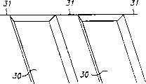
Will speak of as following, two sides 14 may be fragility, that is to say, they can break when cavity 12a and 12b solderless wrapped connection head and the cable that links to each other and electric component are closed.But before packing into, should form the wall of non-leakage liquid together,, just solidify to form gel then so that inject the uncured gel raw material that flows.Fig. 2 is the amplification sectional view of a kind of preferred structure of side 14, and this side comprises a plurality of finger-like sheets 30 that connected by brittle diaphragm 31.Fig. 2 b is its perspective view.When cavity 12a and 12b closed around the cable that stretches out the side outside or electric component, film 31 opened to hold cable or electric component finger-like sheet 30 because of stressed and cracked or tear.In a preferred embodiment, the thickness of finger-like sheet 30 is about 0.81mm (0.032 "), the thickness of film 31 is about 0.051mm (0.002 ").
Be preferably rectangle though should be understood that the shape of box 10 among the figure, that is: two horizontal edge is parallel to each other and perpendicular to side, vice versa also can be other shape.For example, can be that side is taper, perhaps Mo Duan horizontal edge is not a straight line but curved.
Get back to Fig. 1 a and 1b now and look at some other presumable features.Box 10 can be with reinforcement 21 (each cavity 12a or 12b have two pairs), they can reduce elevated temperature (temperature can up to 90 ℃) down during maintenance because the gel expansion in the box and near in box, cause the finger-like sheet 30 deformation, thereby help to keep gel to be in compressive state.We find, preferably adopt more abundant muscle (about 2.8mm, promptly 0.110 " wide), and box is a wide about 38.1mm (1.5 "), is about the rectangle of 114mm (4.5 ") at this moment.If box design is become to be used for manual closing, then the most handy a pair of tongs is clamping near the box middle body and it is being shut.For this reason, can around the 18b of hole, make a reinforcement 25, damage in case when clamping, pass the hasp 17b of hole 18b.For prevent that box from opening under twisting force, be preferably in hasp 17a-17c and go up fluting.For making stress distribution more even and increase opening force, can increase filler rod in the inboard of elasticity locking arm.In the inside of cavity 12a and 12b, aim at and to be provided with that projection 22 helps to treat closed joint with spacing block 23 and the location of cable and electric component and it is held in place of linking to each other.In the intersection of these inner surfaces, for example add a little filler rods 32 with its horizontal edge intersection in the intersection and the cavity bottom surface of projection 22 vertical wall and cavity 12a and 12b bottom surface, will help the mobile and reduction of gel to close required power.
The installation method of box is shown in Fig. 3 a and 3b among the present invention.Common H-frame shape joint 40 shown in Fig. 3 a is connected with cable 42 cable 41 and remains on appropriate location in the box 10 with 43.(components identical among the figure of same numeral and front.For avoiding making figure in disorder unclear, will all not put on numeral with all elements that preceding figure repeats.) should be understood that an ad hoc structure that advances scene 2 only is as an example among this figure, in fact can be other form, one-in-and-one-out for example, two advance scene 2 etc.In addition, cable 41 not necessarily only links to each other with other cables, also can link to each other with the electric component of switching device or transformer one class.Box 10 is to be in local off-position among the figure, can press down and box is closed fully in the position shown in arrow f and the g with hand or a pair of tongs.Baffle plate 16a and 16b make gel flow along horizontal direction when as previously mentioned, shutting box.Fig. 3 b represents the box that solderless wrapped connection 40 and the cable 41,42,43 that is connected by it are closed.We can see the gel 24 that oozes out from end face, and this represents good seal.
In a preferred embodiment, joint 40 can be a kind of joint (IDC) that removes insulating barrier, also is called the joint (IPC) of insulation-piercing layer in the art.This joint comprises dentation sheet, sword sheet or other sharp object, is used for the insulation-piercing layer to electrically contact and do not need insulating barrier is peelled off so that form with following conductor.This structure is shown in Fig. 4, and joint 40 wherein has tooth 45, can pierce through the insulating barrier 48 and 49 and electrically contact with following conductor 51 and 52 of cable 41 and 42, thereby realizes the electrical connection between two conductors.Gel 24 can infiltrate between the slit in the joint 40.
" gel " this speech comprises in prior art from the grease to the thixotropic composition so that this big series material of polymer of fluid dilution.In this manual, " gel " is meant a class solid material that was diluted by the fluid diluent.Gel is a kind of dilution system basically, and it does not have the flow behavior of stable state." viscoplasticity of polymer " (" Viscoelastic Propertiesof Polymers ") 529 pages of (J.Wiley ﹠amp of the third edition as Ferry; Sons, New York, 1980) in pointed, polymer gel is a kind of crosslinker solution that is linked up by chemical bond or crystallite or other certain crosslinking points.Not having steady-flow is the outstanding feature with solid property, and degree of depth dilution is to make the modulus of gel low necessary.The characteristic of solid realizes owing to having formed continuous net-shaped structure in the material, and this structure generally is by certain crosslinking points in the polymer or produces and replace the farmland uniting of multiple minute fork chain and form the crosslinked of polymer chain and obtain.This crosslinked can be physics or chemistry, as long as its position can continue to keep under the service condition of gel.
Wish among the present invention that the preferred gel that adopts is silicone (organopolysiloxane) gel, the U.S. Pat 4,634 of the fluid dilution system of mentioning in for example following patent: Debbaut, 207 (1987) (calling " Debbaut ' 207 " in the following text), people's such as Camin U.S. Pat 4,680,233 (1987), people's such as Dubrow U.S. Pat 4,777,063 (1988), and people's such as Dubrow U.S. Pat 5,079,300 (1992) (calling " Dubrow ' 300 " in the following text).The content of these patents is all quoted as a reference by the present invention.The silicone gel of these fluid dilutions can produce with draw the non-reacting fluid diluent described in the patent as the front, or be used as a kind of diluent with the excessive response liquid such as silicone fluid that for example are rich in ethene and produce, as road-Syland 527 products of healthy and free from worry (Dow-Corning) company or the U.S. Pat 3 of Nelson, disclosed goods in 020,260 (1962).Because these gels need to solidify in preparation, sometimes they are called the hot curing gel.A kind of particularly preferred gel is the silicone gel of being made by the mixture of following material: the dimethyl silicone polymer of divinyl end-blocking, four (dimethyl silane oxygen base) silane, platinum divinyl tetramethyl disiloxane complex (american chemical technology company is on sale), dimethyl silicone polymer, and 1,3,5,7-tetrem thiazolinyl tetramethyl-ring tetrasiloxane (as reacting polymerization inhibitor) to guarantee enough adhesive pot lives.The Valand hardness of this gel is at 10-20g, and viscosity is at 10-36g, and the stress relaxation degree is less than 55%.This gel can be bought to Reychem company together with the GDS gel tapping type connector box that is used for the coaxial cable television set joint (GDS Gel Drop SpliceClosure).This product is in the U.S. Pat 4,988 of Gronvall, explanation also arranged in 894 (1991), and this patent is also quoted as a reference by the present invention.
Also can be with the gel of other type, the U.S. Pat 5 of for example above-mentioned Debbaut ' 261 and Debbaut, 140, the polyurethane gle of mentioning in 476 (1991) (the calling " Debbaut ' 476 " in the following text), with styrene-ethylene butylene-styrene (SEBS) or with styrene-ethylene propylene-styrene (SEPS) is base and through cycloalkanes or non-aromatic or contain the gel of a kind of flux oil dilution of low aromatic series hydrocarbon ils, U.S. Pat 4 as Chen, 369,284 (1983), the U.S. Pat 4,716 of Gamarra etc., 183 (1987) and the U.S. Pat 4 of Gamara, mentioned in 942,270 (1990).SEBS and SEPS gel comprise glassy styrene microfacies, and this microfacies is linked together by the elasticity of fluid dilution.Be used as the tie point of system by the styrene zone of microphase-separated.SEBS and SEPS gel are the examples of thermoplasticity system.When adopting the thermoplastic gel, just do not require that side 14 enbrittles, because this gellike need not to solidify.
Another kind ofly can consider that the gel that adopts is an EPDM rubber-based gel, described in the U.S. Pat 5,177,143 (1993) of Chang etc.But, this gellike has the trend of continuous curing, therefore As time goes on becomes really up to the mark.
Also having the suitable gel of a class is base to contain anhydride polymer, described in the patent WO96/23007 (1996) of Raychem.This patent is also quoted for referencial use by the present invention.Thermal endurance according to this gellike of report is good especially.
Gel can comprise various additives, comprise stabilizer and antioxidant, as hindered phenol (as Irganox1074 (Ciba)), phosphite (as Weston DPDP (General Electric Co. Limited)), sulfide (as Cyanox LTDP (U.S. Cyanamid)), light stabilizer (as Cyasorb UV-531 (U.S. Cyanamid)) and for example halogenated paraffin (as the Bromoklor50 of Ferro) and/or phosphorous organic compound fire retardants such as (as Fyrol PCF and the Phosflex 390 of Akzo Nobel).Other proper additive comprises that pigment, pesticide, tackifier selects material of explanation in the book " plastic additive " that companies' (The International Plastics Seletor) (California Diego California) publish the 1st edition (" Additives ForPlastics, Edition 1 ") like D.A.T.A company and international plastics.
The hardness range of gel is very wide, and it is approximately 1~100g with the value that Voland structural analysis instrument records, preferably 1-30g.Its stress relaxation degree is wished less than about 85%.Viscosity generally greater than about 1g, is preferably greater than 5g.For different purposes, hardness, viscosity and stress relaxation degree can be regulated.Elongation is preferably greater than 50%, preferably greater than 200~300%.Elongation is pressed the ASTMD-638 program determination.
Valand hardness, stress relaxation degree and viscosity can be measured with the TA-XT2 type structural analysis instrument or the similar instrument of LFRA type Voland-Stevens structural analysis instrument, structure technology company.Instrument comprises and is used for pallet and the diameter 1/4 of five kilograms dynamometer of the power of measuring, a 5g " stainless steel ball measuring head (6.35mm), these have explanation in Dubrow ' 300, and its content is all quoted as a reference by the present invention.For example when measuring the thickness of gel, a 60ml vial that about 20 gram gels are housed, " thick gel thin slice places the structural analysis instrument of structure technology company, then measuring head is depressed into the degree of depth that reaches 4.0mm in the gel with the speed of per second 0.2mm in or folded nine 2 " * 2 " * 1/8.The Voland hardness of gel is exactly that what got off by a computer recording is the power of unit with the gram, and this power is for measuring head being pressed into gel surface with above-mentioned speed or making this gel surface distortion 4.0mm needed.The high more expression gel of numeral is hard more.Analyzed by an IBM PC or similar computer by the data that TA-XT2 structural analysis instrument is obtained, used software is the software XT.RA.Dimension2.3 version of microsoft system company (Microsystems Ltds).
Viscosity and stress relaxation degree can be read from the stress curve that the force-time curve that operation XT.RA Dimension 2.3 editions softwares are drawn is automatically derived, this power be when penetration speed be 2.0mm/ second and measuring head be pressed into the about 4.0mm of gel apart from the time dynamometer power of being born.Measuring head was kept under the penetration depth of 4.0mm 1 minute, then with the 2.00mm/ speed dial-out of second.The stress relaxation degree is a ratio of representing with percentage, and its molecule is the power (Ff) of contending with and contending with measuring head after the starting force (Fi) of measuring head deducts 1 minute at predefined penetration depth place, and denominator is Fi.That is to say that the stress relaxation degree of representing with percentage is:
Fi and Ff are unit with the gram in the formula.In other words, the stress relaxation degree is exactly that starting force deducts power after 1 minute again divided by starting force, and it is that gel is to any loose ability of bringing out compression that is added to above it.Viscosity is to be pulled outwardly when transfering to gel the power of contending with (is unit with the gram) on it from predefined penetration depth with the speed of 2.00mm/ second when measuring head.
The another kind of method that characterizes gel characteristic is the cone penetration parameter that adopts according to ASTM D-217, this is at Debbaut 361, Debbaut ' 207, people's such as Debbaut ' 746 and Debbaut U.S. Pat 5,357, explanation is all arranged in 057 (1994), and these patents are all quoted as a reference by the present invention.Cone penetration (" CP ") value is about 70 (10
-1Mm) to about 400 (10
-1Mm).The general CP value of harder gel is about 70 (10
-1Mm) to about 120 (10
-1Mm) about.Softer gel then is about 200 (10
-1Mm) to 400 (10
-1Mm), wish most about 250 (10
-1Mm) to 375 (10
-1Mm).For a kind of specific material system, can find out CP and as be relation between the Voland hardness of unit with the gram, described in people's such as Dittmer U.S. Pat 4,852,646 (1989).We have quoted this patent as a reference.
Though box of the present invention is specially adapted to the protection that rated voltage is the power cable connector of 1000V; at this moment temperature fluctuation can be up to 90 ℃ even 130 ℃; it also is applicable to the connection of other type cable; the for example connection of the cable of transmission communication signal between a cable and another electric power or electric equipment (as transformer, switching device or signal interruption equipment).Box of the present invention is effective especially to the infringement that prevents moisture.
For the sealing property of box of the present invention is described, we use the sample of H bifurcated compression joints to carry out test by ANSI C119.1-1986 (4.3 save) to 12 kinds, comprising six 1/0 main lines and #8AWG branch type joint and six 2/0 main lines and #8AGW branch type joint.In the test, we are immersed in sample in the water and change cold and hot temperature, measure its electrical property respectively when on-test during with different interstages and off-test.We and do not go to describe in detail the details in 17 stages in the test process, only point out to test the insulation resistance that generally requires sample and when the test beginning, be at least 1.0 * 10
6Ohm is at least 1.0 * 10 when EOT
9At least 90% of ohm or reservation initial value, and final ac leakage stream is not more than 1000 μ A.When in fact, the insulation resistance of sample begins 5.2 * 10
11~3.5 * 11
12Ohm, during end 1.5 * 10
11~5.0 * 10
12Ohm, leakage current is at 250~270 μ A.
Comprise in the above detailed description of the invention that some are main or just and the relevant chapters and sections of concrete part or aspect of invention.But should be understood that this is just clear and convenient for what narrate.In fact, a specific character may be far away just not relevant with the paragraph of mentioning it, and its content comprises all suitable combinations of information in each chapters and sections.Equally, though each accompanying drawing of mentioning is with relevant with specific embodiments of the present invention to its explanation, but also should be understood that, a specific feature is described with a concrete accompanying drawing, but this feature to a certain extent can be with another feature of describing with another accompanying drawing or used jointly in the present invention.
Claims (13)
1. gel-filled box from the joint of outer protection stube cable and at least one electric component, it comprises:
First and second cavitys, each cavity have two horizontal edges and two sides to surround inner chamber;
One connects the hinge of these two cavitys along a horizontal edge of first and second each cavitys, and cavity can be around this hinge through and around joint and that part of cable and at least one electric component of next-door neighbour are closed with it;
Basically fill with the gel of first and second each cavitys;
It is characterized in that also comprising:
First baffle plate of the upper surface of described horizontal edge is extended and stretches out on a edge on first cavity away from the horizontal edge of this hinge, extend and stretch out the second baffle of the upper surface of described horizontal edge away from the horizontal edge of this hinge with an edge on second cavity, when this first and second cavity is closed, this first and second baffle plate overlaps the covering stream of gel each other, and guiding gel lateral flow; And
Guarantee that cavity is in the retaining mechanism of closed condition.
2. the gel-filled box of claim 1 is characterized in that, each bar side all is a fragility.
3. the gel-filled box of claim 2 is characterized in that, described every side comprises a plurality of finger-like sheets, and these finger-like sheets are connected to each other together by brittle diaphragm.
4. claim 1 or 3 gel-filled boxes, it also is provided with a plurality of aligning hasps along the horizontal edge away from first cavity of hinge, the edge is provided with a plurality of mating holes away from the horizontal edge of second cavity of hinge, and size and the position of aiming at hasp and mating holes should make that described aligning hasp inserts in the corresponding mating holes when first and second cavitys are closed.
5. the gel-filled box of claim 4, it is characterized in that, the aligning hasp comprises: be contained in first aligning hasp near one of described side, another second of locating who is contained near described side aims at hasp, and is contained in the 3rd aligning hasp in the middle of the first and second aligning hasps basically.
6. claim 1 or 3 gel-filled boxes is characterized in that described box is made with acrylic polymers.
7. claim 1 or 3 gel-filled boxes is characterized in that gel is a silicone gel.
8. claim 1 or 3 gel-filled boxes is characterized in that retaining mechanism comprises a plurality of springlocks.
9. claim 1 or 3 gel-filled boxes is characterized in that hinge is a hinges.
10. claim 1 or 3 gel-filled boxes is characterized in that, at least one electric component is a cable.
11. claim 1 or 3 gel-filled boxes is characterized in that, add filler rod at the intersection of these cavity inner surfaces.
12. claim 1 or 3 gel-filled boxes is characterized in that, each piece baffle plate extends along the length of the horizontal edge that each corresponding baffle plate is housed.
13. claim 1 or 3 gel-filled boxes is characterized in that, described joint is a kind of joint that removes insulating barrier.
Applications Claiming Priority (2)
| Application Number | Priority Date | Filing Date | Title |
|---|---|---|---|
| US08/550,729 US5763835A (en) | 1995-11-01 | 1995-11-01 | Gel-filled closure |
| US08/550,729 | 1995-11-01 |
Publications (2)
| Publication Number | Publication Date |
|---|---|
| CN1205805A CN1205805A (en) | 1999-01-20 |
| CN1113427C true CN1113427C (en) | 2003-07-02 |
Family
ID=24198367
Family Applications (1)
| Application Number | Title | Priority Date | Filing Date |
|---|---|---|---|
| CN96199247A Expired - Lifetime CN1113427C (en) | 1995-11-01 | 1996-10-30 | Gel-filled closure |
Country Status (8)
| Country | Link |
|---|---|
| US (2) | US5763835A (en) |
| EP (1) | EP0858681A1 (en) |
| JP (1) | JP3920340B2 (en) |
| CN (1) | CN1113427C (en) |
| AU (1) | AU7481396A (en) |
| BR (1) | BR9611172A (en) |
| CA (1) | CA2236434A1 (en) |
| WO (1) | WO1997016869A1 (en) |
Families Citing this family (81)
| Publication number | Priority date | Publication date | Assignee | Title |
|---|---|---|---|---|
| US5432486A (en) * | 1993-05-20 | 1995-07-11 | Northern Telecom Limited | Capacitive and inductive coupling connector |
| GB9515502D0 (en) * | 1995-07-28 | 1995-09-27 | Raychem Ltd | Sealing enclosure device |
| DE19741603A1 (en) * | 1997-09-20 | 1999-03-25 | Volkswagen Ag | Electrical contacting arrangement |
| US5990420A (en) * | 1997-12-12 | 1999-11-23 | Ncr Corporation | Cable securing system |
| ES1042153Y (en) * | 1998-12-22 | 2000-01-16 | Mecanismos Aux Ind | METHOD FOR THE COLLECTIVE PROTECTION OF FLAT CABLE CLAMPS. |
| ES1042154Y (en) * | 1998-12-22 | 2000-01-16 | Mecanismos Aux Ind | METHOD FOR INDIVIDUAL PROTECTION OF FLAT CABLE RATCHES. |
| US6169250B1 (en) * | 1999-04-29 | 2001-01-02 | 3M Innovative Properties Company | Low voltage re-enterable splice enclosure |
| IT1309204B1 (en) * | 1999-05-06 | 2002-01-16 | Cabit S R L | TERMINALS FOR THE CONNECTION OF CABLES, ELECTRIC AND NON-ELECTRIC POWER CONDUCTORS. |
| US6475329B1 (en) | 1999-10-04 | 2002-11-05 | Tyco Electronics Corporation | Primer for silicone compositions |
| US6265665B1 (en) | 1999-11-30 | 2001-07-24 | Homac Manufacturing Company | Gel-filled casing for an electrical connection and associated method |
| DE60120119D1 (en) | 2000-03-07 | 2006-07-06 | Tyco Electronics Raychem Nv | CABLE SEAL |
| US6730847B1 (en) | 2000-03-31 | 2004-05-04 | Tyco Electronics Corporation | Electrical connection protector kit and method for using the same |
| US6706968B2 (en) | 2000-04-24 | 2004-03-16 | Tyco Electronics Corporation | Environmentally sealed wrap-around sleeves having a longitudinal sealant chamber |
| US6545219B1 (en) | 2000-04-24 | 2003-04-08 | Tyco Electronics Corporation | Wrap-around cable sleeves having an expandable body portion and methods of making same |
| US6627818B2 (en) | 2000-10-02 | 2003-09-30 | Tyco Electronics Corporation | Electrical connection protector kit and method for using the same |
| US6333463B1 (en) | 2000-11-17 | 2001-12-25 | Tyco Electronics Corporation | Wire separators having sealant material reservoirs and cable splice closures employing such separators |
| TW534487U (en) * | 2001-02-23 | 2003-05-21 | Hon Hai Prec Ind Co Ltd | Filtering device for cable connector |
| US6854996B2 (en) * | 2002-12-20 | 2005-02-15 | Tyco Electronics Corporation | Electrical connectors and methods for using the same |
| WO2004075359A1 (en) * | 2003-02-18 | 2004-09-02 | Homac Mfg. Company | Connector and insulating boot for different sized conductors and associated methods |
| US7044761B2 (en) * | 2003-04-10 | 2006-05-16 | Panduit Corp. | Transparent insulating enclosure |
| DE10326318B3 (en) * | 2003-06-11 | 2005-03-03 | Tyco Electronics Amp Gmbh | Sealing device for an electrical connection point |
| JP3875662B2 (en) * | 2003-07-11 | 2007-01-31 | 矢崎総業株式会社 | Shield processing structure of shielded wire |
| US7044776B2 (en) * | 2003-12-02 | 2006-05-16 | King Jr Lloyd Herbert | Wire connector |
| US7214735B2 (en) * | 2004-02-02 | 2007-05-08 | 3M Innovative Properties Company | Microsphere-filled sealant materials |
| US7141738B2 (en) * | 2004-02-02 | 2006-11-28 | 3M Innovative Properties Company | Re-enterable splice enclosure |
| US6948976B2 (en) * | 2004-03-01 | 2005-09-27 | Andrew Corporation | Cable and apparatus interface environmental seal |
| US6955558B1 (en) | 2004-04-26 | 2005-10-18 | Andrew Corporation | Cable and apparatus interface security device |
| US7172452B1 (en) * | 2004-06-01 | 2007-02-06 | Jason Jay Laws | Modular cable guide |
| US20060254799A1 (en) * | 2005-05-24 | 2006-11-16 | Gregorek Mark R | Instant wire splice wrap |
| US7075012B1 (en) * | 2005-06-03 | 2006-07-11 | 3M Innovative Properties Company | Terminal box |
| JP2007018894A (en) * | 2005-07-08 | 2007-01-25 | Mitsubishi Cable Ind Ltd | Connector cover |
| US7378593B2 (en) * | 2005-07-26 | 2008-05-27 | Tyco Electronics Corporation | Electrical connection protector kits, insert assemblies and methods for using the same |
| US7109423B1 (en) | 2005-07-26 | 2006-09-19 | Tyco Electronics Corporation | Electrical connection protector kits, insert assemblies and methods for using the same |
| ITFI20050185A1 (en) * | 2005-08-31 | 2007-03-01 | Belisario Pini | CASE FOR ELECTRICAL CONNECTIONS AND PROCEDURE FOR MANUFACTURING A SHEET |
| US7550672B2 (en) * | 2005-09-06 | 2009-06-23 | Fci Americas Technology, Inc. | Electrical connector and conductor assembly cover |
| US7201596B1 (en) | 2006-01-06 | 2007-04-10 | Tyco Electronics Corporation | Electrical connector systems, plug systems and methods for using the same |
| CN101170247B (en) * | 2006-10-27 | 2010-05-19 | 3M新设资产公司 | Re-accessible connector enclosing cover |
| US7431611B2 (en) * | 2006-11-07 | 2008-10-07 | The Patent Store, Llc | Wire connector |
| US7384297B2 (en) * | 2006-11-07 | 2008-06-10 | King Jr Lloyd Herbert | Wire connector |
| US7432445B2 (en) * | 2006-12-18 | 2008-10-07 | Ford Global Technologies, Llc | Wire inline T tap/splice |
| US8431647B2 (en) * | 2006-12-27 | 2013-04-30 | Bluestar Silicones France Sas | Adhesive silicone compositions and adhesive bonding/seaming therewith |
| DE102006061599A1 (en) | 2006-12-27 | 2008-07-03 | Cellpack Gmbh | Filling and sealing system for electrically insulating housings and enclosures for holding cable and wire connections |
| US7477826B2 (en) | 2007-01-16 | 2009-01-13 | Tyco Electronics Corporation | Cable enclosure assemblies and methods for using the same |
| US7736187B2 (en) * | 2007-03-20 | 2010-06-15 | Tyco Electronics Corporation | Electrical connector assemblies and joint assemblies and methods for using the same |
| US7950956B2 (en) * | 2007-04-12 | 2011-05-31 | The Patent Store Llc | Tracer wire connector kits |
| US7736165B2 (en) * | 2007-07-16 | 2010-06-15 | Tyco Electronics Corporation | Electrical connector assemblies and methods for forming and using the same |
| US7562864B2 (en) * | 2007-10-09 | 2009-07-21 | Robbins Iii Edward S | Fence splice cover assembly |
| US8038104B1 (en) * | 2008-06-01 | 2011-10-18 | Westek Electronics, Inc. | Cable constraining device for reduced cable wear |
| US7878462B1 (en) * | 2008-06-01 | 2011-02-01 | Larkin Kevin B | Cable constraining device for reduced cable wear |
| US8718434B2 (en) * | 2008-07-01 | 2014-05-06 | Adc Telecommunications, Inc. | Cable enclosure with sealed cable entry port |
| US7845990B2 (en) * | 2008-07-31 | 2010-12-07 | Tyco Electronics Corporation | Connection enclosure assemblies, connector systems and methods for forming an enclosed connection between conductors |
| US7686661B2 (en) * | 2008-07-31 | 2010-03-30 | Tyco Electronics Corporation | Connection enclosure assemblies, connector systems and methods for forming an enclosed connection between conductors |
| JP2012503307A (en) * | 2008-09-16 | 2012-02-02 | コーニンクレッカ フィリップス エレクトロニクス エヌ ヴィ | Polymer wavelength conversion element |
| CA2988835C (en) * | 2008-11-18 | 2020-01-21 | Tyco Electronics Corporation | Sealant-filled enclosures and methods for environmentally protecting a connection |
| WO2010059619A2 (en) * | 2008-11-18 | 2010-05-27 | Tyco Electronics Corporation | Sealant-filled enclosures and methods for environmentally protecting a connection |
| CN102498627B (en) | 2008-11-18 | 2015-09-30 | 泰科电子有限公司 | Sealant filled type sealing cover and the method for environmental protection is carried out for butt joint |
| US7833038B1 (en) * | 2009-04-08 | 2010-11-16 | King Jr Lloyd Herbert | Inline push-in wire connectors |
| US8415564B2 (en) * | 2009-11-04 | 2013-04-09 | Tyco Electronics Corporation | Wrap-around cable sleeve assemblies and methods for making and using the same |
| CN201829633U (en) * | 2010-08-18 | 2011-05-11 | 泰科电子(上海)有限公司 | Sealed junction box |
| US8748741B2 (en) | 2010-10-25 | 2014-06-10 | Tyco Electronics Corporation | Corrosion resistant multiple tap connectors |
| DE102011001576A1 (en) | 2011-03-25 | 2012-09-27 | Tyco Electronics Raychem Gmbh | Cable sleeve for isolating and protecting mechanically interconnected cable ends of e.g. cable connection, has reservoir receiving portion of gel during assembling sleeve and partially extended adjacent to chamber |
| DE102011001578A1 (en) * | 2011-03-25 | 2012-09-27 | Tyco Electronics Raychem Gmbh | Cable sleeve for e.g. cable coupling to insulate and protect mechanically connected copper cable ends, has sealing element comprising longitudinal stock for lengthening sealing element under action of external force on sealing element |
| EP2523287A1 (en) * | 2011-05-10 | 2012-11-14 | Tyco Electronics Raychem BVBA | Cable sealing device having a seal containment wall having movable portions for accomodating cables of different sizes |
| KR101199042B1 (en) * | 2012-06-05 | 2012-11-07 | 최청희 | Gel-coated tubes with hardened wire connection and the branch unit |
| WO2014165229A1 (en) | 2013-03-12 | 2014-10-09 | Tyco Electronics Corporation | Hybrid thermoplastic gels and their methods of making |
| CN107534245B (en) * | 2015-09-14 | 2019-12-24 | 京瓷株式会社 | Branch connector |
| US9837735B2 (en) * | 2016-02-11 | 2017-12-05 | Sumitomo Wiring Systems, Ltd. | Cover with integrated hinge and locking mechanism for vehicle electrical system component |
| CN105633701B (en) * | 2016-03-29 | 2017-12-15 | 中国工程物理研究院核物理与化学研究所 | A kind of coaxial radio frequency cable runs through seal |
| FR3053748B1 (en) * | 2016-07-06 | 2018-07-13 | A Raymond Et Cie | REINFORCED TORSION BAR HING ASSEMBLY |
| US11600874B2 (en) * | 2016-12-16 | 2023-03-07 | Sanyo Electric Co., Ltd. | Electrical equipment battery for vehicles |
| KR101754811B1 (en) * | 2017-01-16 | 2017-07-06 | 제룡산업 주식회사 | Insulation cover of a electric wire sleeve for live front operate in distribution line |
| US10283954B2 (en) * | 2017-07-28 | 2019-05-07 | Nicholas T. Tavare | Connection shield for power distribution networks |
| EP3762753A4 (en) * | 2018-03-09 | 2021-11-10 | CommScope Technologies LLC | Cable seals with reinforcements |
| US10840615B2 (en) | 2018-06-28 | 2020-11-17 | Te Connectivity Corporation | Connection enclosure assemblies, connector systems and methods for forming an enclosed connection between conductors |
| DE202019101892U1 (en) * | 2019-04-02 | 2020-07-03 | Rehau Ag + Co | Single seal |
| CN110296762A (en) * | 2019-07-29 | 2019-10-01 | 鹤壁天海环球电器有限公司 | A kind of seal protecting device of temperature sensor |
| US11271381B2 (en) * | 2019-09-20 | 2022-03-08 | Baker Hughes Oilfield Operations Llc | Systems and methods for subsea wiring splices |
| US11515696B2 (en) * | 2019-12-17 | 2022-11-29 | Te Connectivity Solutions Gmbh | Electrical component enclosure with injected seal and method |
| US11431114B2 (en) * | 2020-02-14 | 2022-08-30 | Te Connectivity Solutions Gmbh | Enclosed connection systems for forming an enclosed connection between conductors, and methods including same |
| DE102021103302B3 (en) | 2021-02-12 | 2022-02-10 | Krüger-Werke GmbH | Inline belay device |
| DE202021106060U1 (en) | 2021-11-05 | 2023-02-13 | Krüger-Werke GmbH | Splicing device with housing for electric cables |
Family Cites Families (34)
| Publication number | Priority date | Publication date | Assignee | Title |
|---|---|---|---|---|
| US3147338A (en) * | 1961-08-15 | 1964-09-01 | Harold N Ekvall | Longitudinally divided hinged insulating connector covers |
| US3183302A (en) * | 1962-01-08 | 1965-05-11 | Jasper Blackburn Corp | Cover for an electrical connector |
| NL130146B (en) * | 1964-07-24 | |||
| US3325591A (en) * | 1965-11-30 | 1967-06-13 | Amp Inc | Insulative cover for a connection assembly |
| US3484541A (en) * | 1968-09-27 | 1969-12-16 | Anderson Electric Corp | Electrical connector cover |
| US3757031A (en) * | 1972-05-02 | 1973-09-04 | Thomas & Betts Corp | The like selectively closable protective enclosure for electrical splices and |
| US3879575A (en) * | 1974-02-21 | 1975-04-22 | Bell Telephone Labor Inc | Encapsulating compound and closure |
| US3875325A (en) * | 1974-06-10 | 1975-04-01 | Western Electric Co | Telephone splice closure |
| US4643505A (en) * | 1980-11-03 | 1987-02-17 | Tri-Cities Tool & Die Clinic, Inc. | Extension cord connector housing |
| US4392014A (en) * | 1981-04-20 | 1983-07-05 | Northern Telecom Limited | Telephone cable splices |
| US4451696A (en) * | 1982-11-15 | 1984-05-29 | Amp Incorporated | Toolless splice sealant device |
| US4647713A (en) * | 1984-10-25 | 1987-03-03 | Nijs Jacob De | Pressurized telecommunication cable joint closure method and apparatus |
| US4909756A (en) * | 1985-01-04 | 1990-03-20 | Raychem Corp. | Splice case |
| US4701574A (en) * | 1985-02-06 | 1987-10-20 | Raychem Corp. | Cable sealing apparatus |
| US4736071A (en) * | 1986-03-17 | 1988-04-05 | American Telephone And Telegraph Company, At&T Bell Laboratories | Encapsulation system with pressurization means |
| US4818824A (en) * | 1987-08-19 | 1989-04-04 | American Telephone And Telegraph Company, At&T Bell Laboratories | Closure for aerial telephone cable splices |
| US4795857A (en) * | 1988-01-29 | 1989-01-03 | Gardenamerica Corporation | Waterproof housing for the spliced ends of electrical cables |
| US5023194A (en) * | 1988-02-11 | 1991-06-11 | Exar Corporation | Method of making a multicollector vertical pnp transistor |
| US4849580A (en) * | 1988-02-11 | 1989-07-18 | Minnesota Mining And Manufacturing Company | Environmental protection closure for wire splices; and method |
| US4880676A (en) * | 1988-04-05 | 1989-11-14 | Raychem Corporation | Cable sealing apparatus |
| US4859809A (en) * | 1988-04-27 | 1989-08-22 | Raychem Corporation | Splice case |
| US4998894A (en) * | 1988-10-06 | 1991-03-12 | Raychem Corporation | Coaxial cable connector seal |
| US5313019A (en) * | 1988-11-09 | 1994-05-17 | N.V. Raychem S.A. | Closure assembly |
| US4935582A (en) * | 1989-01-06 | 1990-06-19 | United Technologies Automotive, Inc. | Splice enclosure for electrical wires |
| US4963700A (en) * | 1989-04-26 | 1990-10-16 | Minnesota Mining And Manufacturing Company | Closure arrangements for electrical splices |
| JPH0353466A (en) * | 1989-07-19 | 1991-03-07 | Three Bond Co Ltd | Coating member for joint member |
| CA1330454C (en) * | 1989-09-29 | 1994-06-28 | Paul Thompson | Device for securing electrical cords |
| GB9103882D0 (en) * | 1991-02-25 | 1991-04-10 | Raychem Sa Nv | Sealed electrical connector |
| DE69219332T2 (en) * | 1991-06-07 | 1997-11-20 | Raychem Corp | HINGED AND GEL FILLED SAFETY AND ENVIRONMENTAL PROTECTION |
| US5129839A (en) * | 1991-11-20 | 1992-07-14 | Doskocil Manufacturing Company, Inc. | Extension cord connection housing |
| IL111241A (en) * | 1993-10-18 | 1998-02-22 | Raychem Corp | Closure for high voltage cable connections |
| JP2955172B2 (en) * | 1993-12-10 | 1999-10-04 | 矢崎総業株式会社 | Waterproof protective cover |
| US5397859A (en) * | 1993-12-10 | 1995-03-14 | The Whitaker Corporation | Enclosure with sealant for spliced coaxial cables |
| US5525073A (en) * | 1994-06-01 | 1996-06-11 | Raychem Corporation | Environmental protection device with manually operated latch mechanism |
-
1995
- 1995-11-01 US US08/550,729 patent/US5763835A/en not_active Expired - Lifetime
-
1996
- 1996-10-30 BR BR9611172A patent/BR9611172A/en not_active Application Discontinuation
- 1996-10-30 JP JP51747797A patent/JP3920340B2/en not_active Expired - Lifetime
- 1996-10-30 AU AU74813/96A patent/AU7481396A/en not_active Abandoned
- 1996-10-30 US US08/739,647 patent/US5828005A/en not_active Expired - Lifetime
- 1996-10-30 CA CA002236434A patent/CA2236434A1/en not_active Abandoned
- 1996-10-30 EP EP96937056A patent/EP0858681A1/en not_active Withdrawn
- 1996-10-30 CN CN96199247A patent/CN1113427C/en not_active Expired - Lifetime
- 1996-10-30 WO PCT/US1996/017309 patent/WO1997016869A1/en not_active Application Discontinuation
Also Published As
| Publication number | Publication date |
|---|---|
| AU7481396A (en) | 1997-05-22 |
| JPH11515160A (en) | 1999-12-21 |
| US5828005A (en) | 1998-10-27 |
| WO1997016869A1 (en) | 1997-05-09 |
| JP3920340B2 (en) | 2007-05-30 |
| CA2236434A1 (en) | 1997-05-09 |
| MX9803473A (en) | 1998-09-30 |
| CN1205805A (en) | 1999-01-20 |
| EP0858681A1 (en) | 1998-08-19 |
| BR9611172A (en) | 1999-03-30 |
| US5763835A (en) | 1998-06-09 |
Similar Documents
| Publication | Publication Date | Title |
|---|---|---|
| CN1113427C (en) | Gel-filled closure | |
| US7477826B2 (en) | Cable enclosure assemblies and methods for using the same | |
| CN102498627B (en) | Sealant filled type sealing cover and the method for environmental protection is carried out for butt joint | |
| CA2736059C (en) | Electrical connection protector kit and method for using the same | |
| KR100885333B1 (en) | Wrap-around cable sleeves having an expandable body portion and methods of making same | |
| US8178783B2 (en) | Sealant-filled enclosures and methods for environmentally protecting a connection | |
| AU2003213728A1 (en) | Environmentally sealed wrap-around cable sleeves having a longitudinal sealant chamber and methods of making same | |
| KR101634206B1 (en) | Sealant-filled enclosures and methods for environmentally protecting a connection | |
| US8748741B2 (en) | Corrosion resistant multiple tap connectors | |
| EP1207608B1 (en) | Wire separators having sealant material reservoirs and cable splice closures emlploying such separators | |
| CA2616735A1 (en) | Electrical connection protector kits, insert assemblies and methods for using the same | |
| MXPA98003473A (en) | Closure filled with | |
| CA2400029C (en) | Electrical connection protector kit and method for using the same | |
| WO2013021989A1 (en) | Connection structure between multicore cable and multicore connector |
Legal Events
| Date | Code | Title | Description |
|---|---|---|---|
| C06 | Publication | ||
| PB01 | Publication | ||
| C10 | Entry into substantive examination | ||
| SE01 | Entry into force of request for substantive examination | ||
| C14 | Grant of patent or utility model | ||
| GR01 | Patent grant | ||
| CX01 | Expiry of patent term |
Granted publication date: 20030702 |
|
| EXPY | Termination of patent right or utility model |