CN111299563B - Novel bottom pouring type casting machine for casting - Google Patents
Novel bottom pouring type casting machine for casting Download PDFInfo
- Publication number
- CN111299563B CN111299563B CN202010204921.5A CN202010204921A CN111299563B CN 111299563 B CN111299563 B CN 111299563B CN 202010204921 A CN202010204921 A CN 202010204921A CN 111299563 B CN111299563 B CN 111299563B
- Authority
- CN
- China
- Prior art keywords
- longitudinal
- moving
- casting
- transverse
- rack
- Prior art date
- Legal status (The legal status is an assumption and is not a legal conclusion. Google has not performed a legal analysis and makes no representation as to the accuracy of the status listed.)
- Active
Links
Images


Classifications
-
- B—PERFORMING OPERATIONS; TRANSPORTING
- B22—CASTING; POWDER METALLURGY
- B22D—CASTING OF METALS; CASTING OF OTHER SUBSTANCES BY THE SAME PROCESSES OR DEVICES
- B22D41/00—Casting melt-holding vessels, e.g. ladles, tundishes, cups or the like
- B22D41/12—Travelling ladles or similar containers; Cars for ladles
-
- B—PERFORMING OPERATIONS; TRANSPORTING
- B08—CLEANING
- B08B—CLEANING IN GENERAL; PREVENTION OF FOULING IN GENERAL
- B08B15/00—Preventing escape of dirt or fumes from the area where they are produced; Collecting or removing dirt or fumes from that area
- B08B15/02—Preventing escape of dirt or fumes from the area where they are produced; Collecting or removing dirt or fumes from that area using chambers or hoods covering the area
-
- B—PERFORMING OPERATIONS; TRANSPORTING
- B22—CASTING; POWDER METALLURGY
- B22D—CASTING OF METALS; CASTING OF OTHER SUBSTANCES BY THE SAME PROCESSES OR DEVICES
- B22D2/00—Arrangement of indicating or measuring devices, e.g. for temperature or viscosity of the fused mass
-
- B—PERFORMING OPERATIONS; TRANSPORTING
- B22—CASTING; POWDER METALLURGY
- B22D—CASTING OF METALS; CASTING OF OTHER SUBSTANCES BY THE SAME PROCESSES OR DEVICES
- B22D2/00—Arrangement of indicating or measuring devices, e.g. for temperature or viscosity of the fused mass
- B22D2/006—Arrangement of indicating or measuring devices, e.g. for temperature or viscosity of the fused mass for the temperature of the molten metal
-
- B—PERFORMING OPERATIONS; TRANSPORTING
- B22—CASTING; POWDER METALLURGY
- B22D—CASTING OF METALS; CASTING OF OTHER SUBSTANCES BY THE SAME PROCESSES OR DEVICES
- B22D46/00—Controlling, supervising, not restricted to casting covered by a single main group, e.g. for safety reasons
Abstract
The invention discloses a novel bottom pouring type pouring machine for casting, which comprises a rack, a track arranged on the rack, a moving mechanism and a ladle hanging mechanism, wherein the moving mechanism and the ladle hanging mechanism are arranged above the track; a weighing mechanism is arranged between the lifting mechanism and the longitudinal moving mechanism, and a temperature measuring mechanism is arranged on the lifting mechanism; the lower part of the rack is provided with a roller way, a dust hood is arranged above the rack, the length of the dust hood is greater than that of the roller way, and two ends of the roller way are provided with transfer vehicles for conveying sand boxes. The novel bottom pouring type casting machine for casting, which adopts the structure, realizes automatic operation of the bottom pouring ladle on a production line, has high operation speed, can use equipment covered by a dust hood, reduces the labor intensity of workers and improves the production efficiency.
Description
Technical Field
The invention relates to the technical field of casting machines, in particular to a novel bottom pouring type casting machine for casting.
Background
In the casting industry, bottom pouring is adopted in the production process for obtaining good casting quality of steel castings. The former production lines, including high-end production lines imported from abroad, adopt manually operated travelling cranes to hoist bottom pouring type casting ladles to a position above a sand box and manually open a pouring gate for casting, and complete dust removal in the casting process cannot be realized due to the influence of travelling crane steel wire ropes in the whole casting process, so that the workshop environment is deteriorated. The driving crane hangs this has very big potential safety hazard of walking back and forth in the workshop of pouring ladle in whole workshop, and this that the driving crane is controlled by the manual work also has personnel misoperation's hidden danger. The travelling crane is hung on a ladle filled with molten steel to operate, so that the running speed of the travelling crane is greatly limited, the whole pouring process is slow, and the requirement of production takt cannot be met. To date there is no suitable apparatus that fully addresses the above problems, which requires the development of an entirely new apparatus to meet these needs of the foundry industry.
Disclosure of Invention
The invention aims to provide a novel bottom pouring type casting machine for casting, which realizes automatic operation of a bottom pouring bag on a production line, has high operation speed, can use equipment covered by a dust hood, reduces the labor intensity of workers and improves the production efficiency.
In order to achieve the purpose, the invention provides a novel bottom pouring type casting machine for casting, which comprises a rack, a track arranged on the rack, a moving mechanism and a ladle hanging mechanism, wherein the moving mechanism and the ladle hanging mechanism are arranged above the track;
a weighing mechanism is arranged between the lifting mechanism and the longitudinal moving mechanism, and a temperature measuring mechanism is arranged on the lifting mechanism;
the lower part of the rack is provided with a roller way, and two ends of the roller way are provided with transfer trucks for conveying sand boxes; and a dust hood is arranged above the rack, and the length of the dust hood is greater than that of the roller way.
Preferably, the transverse moving mechanism comprises a transverse moving beam, a transverse moving longitudinal beam connected with the transverse moving beam and a transverse moving motor fixed on the transverse moving longitudinal beam, the number of the transverse moving motors is two, the transverse moving longitudinal beam is placed on the track of the rack through a traveling wheel, and the transverse moving longitudinal beam and the transverse moving beam are enclosed to form a rectangular structure.
Preferably, the longitudinal moving mechanism comprises a longitudinal moving beam arranged on the transverse moving beam and a longitudinal moving longitudinal beam connected with the longitudinal moving beam, a longitudinal moving motor is arranged outside one end of each of the two longitudinal moving beams, and the longitudinal moving longitudinal beam and the longitudinal moving beam form a rectangular structure.
Preferably, the lifting mechanism comprises a support fixed on the longitudinal moving longitudinal beam and a screw rod arranged on the support, the support comprises a cross beam and a longitudinal beam connected with the cross beam, the longitudinal beam is provided with an L-shaped steering gear and a screw rod lifter, and the cross beam is provided with a lifting motor.
Therefore, the novel bottom pouring type casting machine for casting with the structure has the following beneficial effects: (1) the high precision of the positioning of the casting ladle is ensured, the moving and lifting mechanisms are driven by a servo system, the positioning precision of the casting ladle is ensured, and particularly, the repeated quantitative requirement of a large batch of sand boxes can be ensured when the casting ladle is applied on a casting production line;
(2) the running speed of the casting ladle is increased, slow, fast and slow switching is performed during the moving and lifting operation of the equipment, the stable starting and stopping and the fast running can be ensured, and the swinging running speed of the product is much higher than that of a travelling crane because the product is rigidly connected and has no steel wire rope;
(3) the device can realize pouring and dust removal, the sand box during pouring can not be completely covered by the dust hood due to the limitation of a steel wire rope in the traditional mode of lifting the pouring ladle by a travelling crane, and the device can realize full coverage of the dust hood without the limitation;
(4) the automatic operation can be realized in the moving and lifting processes of the casting ladle without manual intervention, so that the labor intensity of workers is reduced, and the production efficiency is improved;
(5) dynamic monitoring, wherein the weight and the temperature of molten steel in a casting ladle are monitored in real time in the whole process, and when the molten steel is insufficient or the temperature is lower than the casting temperature, the molten steel can be automatically suspended and alarm, so that the process that the molten steel enters a sand box is finished in a controllable state;
(6) compatible many specifications end notes package, this device string package mechanism can be compatible many specifications end notes package, satisfies the requirement of different foundry goods pouring crafts.
The technical solution of the present invention is further described in detail by the accompanying drawings and embodiments.
Drawings
FIG. 1 is a schematic structural diagram of an embodiment of a novel bottom pouring type casting machine for casting according to the present invention;
FIG. 2 is a top view of an embodiment of the novel bottom pouring type casting machine for casting of the present invention;
FIG. 3 is a side view of an embodiment of the novel bottom pouring type pouring machine for casting of the present invention;
FIG. 4 is a schematic view of a lateral moving mechanism of an embodiment of the novel bottom pouring type casting machine for casting of the invention;
FIG. 5 is a schematic view of a longitudinal moving mechanism of an embodiment of the novel bottom pouring type casting machine for casting of the invention;
FIG. 6 is a schematic view of an elevating mechanism of an embodiment of a novel bottom pouring type casting machine for casting according to the invention;
FIG. 7 is a top view of the lifting mechanism of the embodiment of the novel bottom pouring type casting machine for casting of the present invention;
fig. 8 is a schematic structural diagram of a ladle hanging mechanism of the embodiment of the novel bottom pouring type casting machine for casting.
Detailed Description
The technical solution of the present invention is further illustrated by the accompanying drawings and examples.
Unless defined otherwise, technical or scientific terms used herein shall have the ordinary meaning as understood by one of ordinary skill in the art to which this invention belongs. The use of "first," "second," and similar terms in the present application do not denote any order, quantity, or importance, but rather the terms are used to distinguish one element from another. The word "comprising" or "comprises", and the like, means that the element or item listed before the word covers the element or item listed after the word and its equivalents, but does not exclude other elements or items. The terms "connected" or "coupled" and the like are not restricted to physical or mechanical connections, but may include typical connections, whether direct or indirect. "upper", "lower", "left", "right", and the like are used merely to indicate relative positional relationships, and when the absolute position of the object being described is changed, the relative positional relationships may also be changed accordingly.
Examples
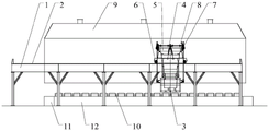
Fig. 1 is a schematic structural diagram of an embodiment of a novel bottom pouring type casting machine for casting according to the present invention, fig. 2 is a top view of an embodiment of a novel bottom pouring type casting machine for casting according to the present invention, fig. 3 is a side view of an embodiment of a novel bottom pouring type casting machine for casting according to the present invention, fig. 8 is a schematic structural diagram of a ladle hanging mechanism of an embodiment of a novel bottom pouring type casting machine for casting according to the present invention, as shown in the drawings, the present invention provides a novel bottom pouring type casting machine for casting, which comprises a frame 1, a rail 2 arranged on the frame 1, a transverse moving mechanism 6 and a longitudinal moving mechanism 5 arranged above the rail 2, wherein the longitudinal moving mechanism 5 is connected with a lifting mechanism 4, and the lower part of the lifting mechanism 4 is connected with the ladle hanging mechanism 3; a weighing mechanism 7 is arranged between the lifting mechanism 4 and the longitudinal moving mechanism 5, and a temperature measuring mechanism 8 is arranged on the lifting mechanism 4; the lower part of the frame 1 is provided with a roller way 12, a dust hood 9 is arranged above the frame 1, the length of the dust hood 9 is larger than that of the roller way 12, and two ends of the roller way 12 are provided with transfer vehicles 11 for conveying sand boxes 10. The frame is used for supporting the weight of whole equipment and the ladle of watering, and lateral shifting mechanism is used for realizing the lateral shifting of whole equipment, and longitudinal shifting mechanism is used for realizing the longitudinal shifting of whole equipment, and elevating system is used for realizing the lift of watering the package, and the ladle hanging mechanism is used for realizing that the end of different specifications is annotated the package and is placed in the casting machine, and weighing mechanism is used for realizing watering the real-time supervision of the interior molten steel weight of package, and temperature measuring mechanism is used for realizing watering the real-time supervision of the interior molten steel temperature of package. The above parts act coordinately, so that the product can have six degrees of freedom in the upper, lower, front, rear, left and right directions to completely meet the pouring requirements of sand boxes with different specifications.
Fig. 4 is a schematic diagram of a lateral moving mechanism of an embodiment of the novel bottom-pouring type casting machine for casting, and as shown in the figure, the lateral moving mechanism 6 includes a lateral moving beam 61, a lateral moving longitudinal beam 62 connected with the lateral moving beam 61, and a lateral moving motor 63 fixed on the lateral moving longitudinal beam 62, the number of the lateral moving motors 63 is two, the lateral moving longitudinal beam 62 is placed on the track 2 of the frame 1 through a traveling wheel, and the lateral moving longitudinal beam 62 and the lateral moving beam 61 enclose a rectangular structure.
Fig. 5 is a schematic diagram of a longitudinal moving mechanism of an embodiment of the novel bottom-pouring type casting machine for casting of the present invention, and as shown in the figure, the longitudinal moving mechanism 5 includes a longitudinal moving beam 51 placed on a transverse moving beam 61 and a longitudinal moving longitudinal beam 52 connected with the longitudinal moving beam 51, a longitudinal moving motor 53 is disposed outside one end of the two longitudinal moving beams 51, and the longitudinal moving longitudinal beam 52 and the longitudinal moving beam 51 enclose a rectangular structure.
Fig. 6 is a schematic diagram of an elevating mechanism of an embodiment of a novel bottom pouring type casting machine for casting of the present invention, fig. 7 is a top view of the elevating mechanism of an embodiment of the novel bottom pouring type casting machine for casting of the present invention, as shown in the figure, the elevating mechanism 4 includes a support frame 41 fixed on a longitudinal moving longitudinal beam 52 and a screw 42 arranged on the support frame 41, the support frame 41 is composed of a cross beam 410 and a longitudinal beam 411 connected with the cross beam 410, an L-shaped steering gear 43 and a screw lifter 44 are arranged on the longitudinal beam 411, and an elevating motor 45 is arranged on the cross beam 410.
The working principle is as follows: firstly, a transfer trolley transfers the sand box to a roller way to wait for pouring. The casting machine is driven by the transverse moving mechanism to move to a ladle changing area on the frame, and a casting ladle filled with molten steel is hoisted to the ladle hanging mechanism. The weighing mechanism weighs the weight of molten steel in the ladle, the temperature measuring mechanism measures the temperature of the molten steel in the ladle, if the pouring requirement is met, the pouring machine moves the pouring ladle to the position above the sand box under the driving of the transverse moving mechanism and the longitudinal moving mechanism, the pouring ladle is lowered to the height required by pouring under the driving of the lifting mechanism according to the height of the sand box, and then the water gap of the bottom pouring type pouring ladle is manually opened for pouring. After the pouring is finished, the water gap of the bottom pouring type pouring ladle is manually closed, and the pouring machine is driven by the transverse moving mechanism and the longitudinal moving mechanism to move downwards to the next sand box to repeat the pouring process. And circulating in this way, after the weighing mechanism or the temperature measuring mechanism sends out an alarm which does not meet the pouring requirement, the pouring ladle is lifted to a safe height under the driving of the lifting mechanism, and then is moved to a ladle changing area under the driving of the transverse moving mechanism and the longitudinal moving mechanism, and the empty pouring ladle is lifted away manually, so that the complete pouring process is completed. Therefore, the novel bottom pouring type casting machine for casting with the structure realizes automatic operation of the bottom pouring bag on a production line, has high operation speed, can use equipment covered by the dust hood, reduces the labor intensity of workers and improves the production efficiency.
Finally, it should be noted that: the above embodiments are only for illustrating the technical solutions of the present invention and not for limiting the same, and although the present invention is described in detail with reference to the preferred embodiments, those of ordinary skill in the art should understand that: modifications and equivalents may be made to the invention without departing from the spirit and scope of the invention.
Claims (1)
1. The utility model provides a casting is with novel end formula casting machine of annotating which characterized in that:
the bag hanging device comprises a rack, a track arranged on the rack, and a moving mechanism and a bag hanging mechanism which are arranged above the track, wherein the moving mechanism comprises a lifting mechanism connected with the bag hanging mechanism, a longitudinal moving mechanism and a transverse moving mechanism connected with the lifting mechanism, and the transverse moving mechanism and the longitudinal moving mechanism are both connected with the bag hanging mechanism;
a weighing mechanism is arranged between the lifting mechanism and the longitudinal moving mechanism, and a temperature measuring mechanism is arranged on the lifting mechanism;
the lower part of the rack is provided with a roller way, and two ends of the roller way are provided with transfer trucks for conveying sand boxes;
a dust hood is arranged above the rack, and the length of the dust hood is greater than that of the roller way;
the transverse moving mechanism comprises a transverse moving beam, a transverse moving longitudinal beam connected with the transverse moving beam and transverse moving motors fixed on the transverse moving longitudinal beam, the number of the transverse moving motors is two, the transverse moving longitudinal beam is placed on a track of the rack through a traveling wheel, and the transverse moving longitudinal beam and the transverse moving beam form a rectangular structure;
the longitudinal moving mechanism comprises a longitudinal moving beam arranged on the transverse moving beam and a longitudinal moving longitudinal beam connected with the longitudinal moving beam, the outer sides of one end parts of the two longitudinal moving beams are provided with longitudinal moving motors, and the longitudinal moving longitudinal beam and the longitudinal moving beam form a rectangular structure;
the lifting mechanism comprises a transverse support frame fixed on the longitudinal moving longitudinal beam and longitudinal support beams arranged at two ends of the transverse support frame, the transverse support frame comprises a cross beam and a longitudinal beam connected with the cross beam, an L-shaped steering gear and a lead screw lifter are arranged on the longitudinal beam, and a lifting motor is arranged on the cross beam.
Priority Applications (1)
| Application Number | Priority Date | Filing Date | Title |
|---|---|---|---|
| CN202010204921.5A CN111299563B (en) | 2020-03-22 | 2020-03-22 | Novel bottom pouring type casting machine for casting |
Applications Claiming Priority (1)
| Application Number | Priority Date | Filing Date | Title |
|---|---|---|---|
| CN202010204921.5A CN111299563B (en) | 2020-03-22 | 2020-03-22 | Novel bottom pouring type casting machine for casting |
Publications (2)
| Publication Number | Publication Date |
|---|---|
| CN111299563A CN111299563A (en) | 2020-06-19 |
| CN111299563B true CN111299563B (en) | 2021-09-24 |
Family
ID=71155448
Family Applications (1)
| Application Number | Title | Priority Date | Filing Date |
|---|---|---|---|
| CN202010204921.5A Active CN111299563B (en) | 2020-03-22 | 2020-03-22 | Novel bottom pouring type casting machine for casting |
Country Status (1)
| Country | Link |
|---|---|
| CN (1) | CN111299563B (en) |
Families Citing this family (4)
| Publication number | Priority date | Publication date | Assignee | Title |
|---|---|---|---|---|
| CN111906287B (en) * | 2020-08-23 | 2021-12-17 | 山西一禾铝业科技新材料有限公司 | Alloy casting equipment |
| CN112808988A (en) * | 2021-02-04 | 2021-05-18 | 桑超 | Pouring lift truck |
| CN113751427A (en) * | 2021-09-03 | 2021-12-07 | 中国一冶集团有限公司 | Movable ash and dust removing device in coke oven building process |
| CN114178516A (en) * | 2021-10-26 | 2022-03-15 | 青岛恒林工业集团股份有限公司 | V-normal line walking frame type bottom injection machine |
Citations (7)
| Publication number | Priority date | Publication date | Assignee | Title |
|---|---|---|---|---|
| US4953761A (en) * | 1988-09-27 | 1990-09-04 | Inductotherm Corp. | Stopper rod spatial control mechanism |
| JP2001293553A (en) * | 2000-04-13 | 2001-10-23 | Kubota Corp | Device for pouring molten metal |
| CN103042202A (en) * | 2013-01-24 | 2013-04-17 | 宁波禾顺新材料有限公司 | Automatic pouring system |
| CN104476558A (en) * | 2014-11-26 | 2015-04-01 | 常州南车汽车零部件有限公司 | Manipulator separating and classifying device |
| CN204413128U (en) * | 2014-12-26 | 2015-06-24 | 河北欧耐机械模具有限公司 | Bottom filling servo-hydraulic casting machine |
| CN207057572U (en) * | 2017-07-13 | 2018-03-02 | 东风精密铸造有限公司 | A kind of moltening mold castings molten iron casting machine |
| CN107876710A (en) * | 2017-12-11 | 2018-04-06 | 机械工业第六设计研究院有限公司 | The automatic sand cleaning machine in the face of 3D printing sand mold continous way six and sand removal method |
Family Cites Families (4)
| Publication number | Priority date | Publication date | Assignee | Title |
|---|---|---|---|---|
| JPS56141961A (en) * | 1980-04-03 | 1981-11-05 | Kurosaki Refract Co Ltd | Sliding nozzle device having decarburization and oxidation preventing mechanism using inert gas |
| CN203944830U (en) * | 2013-07-15 | 2014-11-19 | 贵研资源(易门)有限公司 | Plasmamelt process reclaims the casting ladle of noble metal from spent automotive exhaust catalysts |
| CN104860240A (en) * | 2015-04-29 | 2015-08-26 | 安庆旭东工贸有限责任公司 | Motorized model cluster placing truck for evaporative pattern casting |
| CN107790694A (en) * | 2017-10-13 | 2018-03-13 | 首钢集团有限公司 | A kind of basket pouring hole seals device |
-
2020
- 2020-03-22 CN CN202010204921.5A patent/CN111299563B/en active Active
Patent Citations (7)
| Publication number | Priority date | Publication date | Assignee | Title |
|---|---|---|---|---|
| US4953761A (en) * | 1988-09-27 | 1990-09-04 | Inductotherm Corp. | Stopper rod spatial control mechanism |
| JP2001293553A (en) * | 2000-04-13 | 2001-10-23 | Kubota Corp | Device for pouring molten metal |
| CN103042202A (en) * | 2013-01-24 | 2013-04-17 | 宁波禾顺新材料有限公司 | Automatic pouring system |
| CN104476558A (en) * | 2014-11-26 | 2015-04-01 | 常州南车汽车零部件有限公司 | Manipulator separating and classifying device |
| CN204413128U (en) * | 2014-12-26 | 2015-06-24 | 河北欧耐机械模具有限公司 | Bottom filling servo-hydraulic casting machine |
| CN207057572U (en) * | 2017-07-13 | 2018-03-02 | 东风精密铸造有限公司 | A kind of moltening mold castings molten iron casting machine |
| CN107876710A (en) * | 2017-12-11 | 2018-04-06 | 机械工业第六设计研究院有限公司 | The automatic sand cleaning machine in the face of 3D printing sand mold continous way six and sand removal method |
Also Published As
| Publication number | Publication date |
|---|---|
| CN111299563A (en) | 2020-06-19 |
Similar Documents
| Publication | Publication Date | Title |
|---|---|---|
| CN111299563B (en) | Novel bottom pouring type casting machine for casting | |
| CN203316710U (en) | Casting machine | |
| CN106865177A (en) | A kind of turning device and suspender | |
| US4360304A (en) | Extendable crane trolley and method | |
| CN206705188U (en) | A kind of turning device and suspender | |
| CN106563790B (en) | Beam type shake out manipulator and its shake out method | |
| CN109384162B (en) | Gantry type component transport vehicle and component transport method | |
| CN215615045U (en) | Molten iron lifting ladle-to-ladle vehicle | |
| JP2009285689A (en) | Ladle lid carrying apparatus | |
| EP2511222B1 (en) | Method for controlling a concrete mix casting equipment dismountably attached to a crane and a concrete mix casting equipment dismountably attached to a crane | |
| CN203875329U (en) | Lifting ladle support | |
| CN111215616B (en) | Molten metal transfer system | |
| CN210505302U (en) | Hydraulic hoisting and casting device special for steel mill metallurgy | |
| CN213923034U (en) | Intelligent mold grabbing robot for building components | |
| CN114346225B (en) | Ladle covering and uncovering method for rotary double-station RH refining furnace | |
| CN216607216U (en) | Gantry type bottom pouring ladle casting machine | |
| CN220351493U (en) | Double-hook intelligent portal crane | |
| CN219885493U (en) | Lifting trolley of casting crane | |
| CN202804157U (en) | Automatic molten steel casting machine | |
| JP7413155B2 (en) | Ladle changing device for continuous casting equipment | |
| CN219860470U (en) | Limiting mechanism for material hoisting rope in overhaul hanging basket | |
| CN215615041U (en) | Automatic casting pouring line | |
| CN220351516U (en) | Height-adjustable gantry crane | |
| CN211521409U (en) | Horizontal line weight placing mechanism | |
| CN214349585U (en) | Automatic casting system for casting sand box |
Legal Events
| Date | Code | Title | Description |
|---|---|---|---|
| PB01 | Publication | ||
| PB01 | Publication | ||
| SE01 | Entry into force of request for substantive examination | ||
| SE01 | Entry into force of request for substantive examination | ||
| GR01 | Patent grant | ||
| GR01 | Patent grant |