Automatic change afforestation irrigation system
Technical Field
The invention relates to the field of landscaping, in particular to an automatic landscaping irrigation system.
Background
The garden irrigation is to supplement soil moisture of garden greenbelts in different irrigation forms by using an artificial method or a mechanical method to meet the moisture requirement of plants, a garden irrigation system pays attention to the water requirement of the plants, water conservation and energy conservation are considered, the garden irrigation system is convenient and practical, and meanwhile, the garden landscape is brightened and colored to enhance the water landscape of the garden and increase the dynamic landscape effect. Along with the continuous promotion of the urbanization process, the urban ecological and environmental problems are increasingly prominent, and the urban landscaping is used as a main way for maintaining and improving the urban ecological environment to create huge ecological environment and social and economic benefits, but the existing irrigation system is mostly operated manually, so that the intelligent degree is low, time and labor are wasted, the cost is high, and considerable resources and expenses are consumed.
The invention with publication number CN107960307A discloses an irrigation system for landscaping trees, which comprises a garden field, a water storage tank is fixedly arranged on the ground at one side of the garden site, an automatic water adding mechanism is arranged on the water storage tank, the automatic water adding mechanism is provided with a liquid level sensor, a water adding port, a water adding pipe and an electric valve, one side of the water storage tank is provided with a nutrient adding mechanism, the nutrient adding mechanism is provided with a mixing drum, a mixing mechanism, a water inlet, a water pump, a water inlet pipe, a flow counter, a nutrient containing box and a quantitative adding mechanism, the churn is external to have irrigated the mechanism, irrigate the mechanism and be equipped with suction pump, delivery port, solenoid valve, outlet pipe, value tree hole, trees, watering pipe, supporting leg, hold platform, heat preservation mechanism, watering mouth, water-flowing pipe, electronic stop valve, water storage tank top one side is equipped with the controller. The invention has the advantages of simple structure and strong practicability.
However, the above-mentioned devices also have the following problems in use: firstly, although the device can realize irrigation, the position of the spray header cannot be adjusted, so that the spray header can only irrigate plants in a certain range, cannot irrigate remote plants and cannot irrigate crowns of trees, and the practicability is low; second, above-mentioned device utilize the water storage tank to deposit water, exist when having impurity in the water storage tank and carry out the condition of blockking up to the shower head, lead to gardens emergence to irrigate inhomogeneous condition.
Disclosure of Invention
The invention aims to provide an automatic landscaping irrigation system, which aims to solve the technical problems that only plants in a certain range can be irrigated and the irrigation is not uniform due to blockage in the prior art.
The invention provides an automatic landscaping irrigation system, which comprises a liquid storage box, a mixing and stirring mechanism, an infusion pump, a medicament adding mechanism and a greening spraying mechanism, the greening spraying mechanism is arranged at the side of the liquid storage box, the medicament adding mechanism is arranged at the top of the liquid storage box, the infusion pump 3 is arranged between the greening spraying mechanism and the liquid storage box, the mixing and stirring mechanism is arranged inside the liquid storage box, the greening spraying mechanism comprises a swinging plate, a fixed plate, a crown spraying component, a root irrigation component and two fixed seats which are arranged at intervals, the crown spray assembly is arranged at the top of the swinging plate, the fixed plate is horizontally arranged between the two fixed seats, each fixed seat is provided with an installation cylinder which is rotatably connected with the fixed plate, the swing plate is arranged between the two mounting cylinders, and each mounting cylinder is fixedly connected with the swing plate through a bolt.
Further, crown spray set is including the transmission shaft and the spray line of a plurality of and the infusion pipeline intercommunication of driving motor, infusion pipeline, level setting, every spray line's play liquid end all is equipped with atomizing nozzle, every all the cover is equipped with driven gear on the installation section of thick bamboo, the both ends of transmission shaft are respectively with two the fixing base rotates to be connected, the both ends of transmission shaft all are equipped with the driving gear, two the driving gear meshes with two driven gear respectively, driving motor fixes one of them on the lateral wall of fixing base, and driving motor's the output and the tip fixed connection of transmission shaft.
Further, the root irrigation assembly comprises a connecting pipeline and a plurality of irrigation heads, the connecting pipeline is horizontally arranged at the top of the fixing plate, the connecting pipeline is fixed on the fixing plate through a pipe hoop, each connecting pipeline is provided with a plurality of liquid outlet pipelines communicated with the inside of the connecting pipeline, each liquid outlet pipeline corresponds to one irrigation head, and each liquid outlet pipeline and the corresponding irrigation head are provided with a transfusion hose.
Further, the bottom of the liquid storage box is provided with a liquid outlet funnel communicated with the inside of the liquid storage box, the bottom of the liquid outlet funnel is provided with a liquid outlet pipeline, the input end of the infusion pump is communicated with the liquid outlet pipeline, the output end of the infusion pump is provided with a three-way pipe, the connecting pipeline, the liquid outlet pipeline and the three-way pipe are communicated through a hose, the liquid outlet pipeline is provided with a first electromagnetic valve, the connecting pipeline is provided with a second electromagnetic valve, the inside of the liquid storage box is provided with a heater and a temperature sensor, the inner wall of the liquid storage box is provided with a controller, and the heater and the temperature sensor are electrically connected with the controller.
Further, mix rabbling mechanism including stirring vibrations subassembly and the filter screen of level setting in the liquid storage tank inside bottom, stirring vibrations subassembly sets up in the top of filter screen, and the bottom of filter screen is equipped with four supporting seats that are matrix distribution, every all be equipped with vibrations spring on the supporting seat, the bottom and four vibrations spring fixed connection of filter screen.
Further, stirring vibrations subassembly is including axis of rotation and the agitator motor that the level set up, the both ends of axis of rotation rotate with the both sides of depositing the liquid case respectively and are connected, agitator motor's the output and the tip fixed connection of axis of rotation, the cover is equipped with a plurality of stirring paddle leaf in the axis of rotation, the middle section of axis of rotation is equipped with U type pole, the top of filter screen is equipped with articulated seat, be equipped with rather than articulated transfer line on the articulated seat, the cover that the tip of transfer line can move about is established on U type pole.
Further, the medicament adding mechanism is including depositing the medical kit, seal the subassembly and the level sets up the sieve medicine grid in depositing the inside bottom of medical kit, the top of depositing the medical kit is equipped with into medicine mouth, the inside of depositing the medical kit is equipped with four connecting seats that are matrix distribution, every the bottom of connecting seat all is equipped with connecting spring, the top and four connecting spring of sieve medicine grid are connected.
Further, the seal assembly including rotate the motor, with deposit medical kit sliding fit's closing plate and with deposit liquid tank lateral wall fixed connection's mount pad, it sets up the bottom at the mount pad to rotate the motor, the cover is equipped with the drive wheel on the output of rotation motor, rotate to take turns to go up the cover and be equipped with rather than articulated dwang, the tip of dwang is articulated with the tip of closing plate, the top of closing plate is equipped with the removal cam, the bottom of sieve medicine grid is equipped with the extension strip of vertical setting, the bottom of extending the strip is equipped with and removes cam matched with gyro wheel.
Compared with the prior art, the invention has the beneficial effects that:
the tree root irrigation assembly can convey irrigation liquid to a plurality of irrigation heads at regular time, and the tree crown spraying assembly can automatically realize atomization spraying operation on the tree trunk and the tree crown of the tree, so that the technical problems that in the prior art, only plants in a certain range can be irrigated and uneven irrigation is caused by blockage are solved.
Secondly, the irrigation liquid introduced into the liquid storage tank can be stirred and mixed through the mixing and stirring mechanism, the filter screen can filter impurities, and the rotating shaft can vibrate the filter screen in the rotating process so as to avoid the filter screen from being blocked by the impurities.
Thirdly, the tree root irrigation device is provided with a greening spraying mechanism, the greening spraying mechanism comprises a swinging plate, a fixing plate, a tree crown spraying assembly, a tree root irrigation assembly and two fixing seats arranged at intervals, and irrigation liquid can be conveyed to a plurality of irrigation heads at regular time through the tree root irrigation assembly, so that the tree root irrigation device can automatically realize tree root irrigation operation, and the automation degree is high.
Fourthly, the tree crown spraying assembly can automatically realize atomization spraying operation on the trunk and the tree crown of the tree, and can automatically adjust the spraying angle of the atomizing nozzle, so that the atomizing nozzle can spray distant plants, and the practicability of the device is improved.
Fifthly, the nutrient can be intermittently fed into the liquid storage tank through the medicament feeding mechanism, so that the influence on the normal growth of plants due to too much or too little nutrient feeding is avoided, the vibration operation of the medicament sieving grid can be realized, and the influence on the normal feeding amount of the nutrient due to the blockage of the medicament sieving grid is effectively avoided.
Drawings
In order to more clearly illustrate the embodiments of the present invention or the technical solutions in the prior art, the drawings used in the description of the embodiments or the prior art will be briefly described below, and it is obvious that the drawings in the following description are some embodiments of the present invention, and other drawings can be obtained by those skilled in the art without creative efforts.
FIG. 1 is a schematic perspective view of the present invention;
FIG. 2 is a schematic top view of the present invention;
FIG. 3 is a schematic cross-sectional view taken along line A-A of FIG. 2;
FIG. 4 is a schematic perspective view of a greening spraying mechanism;
FIG. 5 is a partial cross-sectional view of the first embodiment of the present invention;
FIG. 6 is an enlarged view of FIG. 5 at B;
FIG. 7 is a partial cross-sectional view of the second embodiment of the present invention;
fig. 8 is an enlarged view at C in fig. 7.
Reference numerals:
a liquid storage tank 1, a liquid outlet funnel 11, a liquid discharge pipeline 12, a three-way pipe 13, a first electromagnetic valve 14, a second electromagnetic valve 15, a mixing and stirring mechanism 2, a stirring and vibrating component 21, a filter screen 22, a support base 23, a vibrating spring 24, a rotating shaft 25, a stirring motor 26, a stirring paddle 27, a U-shaped rod 271, a hinge base 272, a transmission rod 28, a liquid delivery pump 3, a medicine adding mechanism 4, a medicine storage tank 41, a medicine inlet nozzle 42, a closing component 43, a rotating motor 431, a closing plate 432, a transmission wheel 433, a rotating rod 434, a moving cam 435, an extension bar 44, a roller 45, a mounting base 46, a medicine sieving grid 461, a connecting spring 47, a connecting base 471, a greening spraying mechanism 5, a swinging plate 51, a fixing plate 52, a root irrigation component 53, a fixing base 531, a mounting cylinder 532, a connecting pipeline 533, an irrigation head 54, a liquid discharge pipeline 55, a liquid delivery hose 56, a tree crown spraying component 6, a driving motor 61, the device comprises a liquid conveying pipeline 62, a transmission shaft 63, a spraying pipeline 64, an atomizing nozzle 65, a driven gear 66 and a driving gear 67.
Detailed Description
The technical solutions of the present invention will be described clearly and completely with reference to the accompanying drawings, and it should be understood that the described embodiments are some, but not all embodiments of the present invention.
The components of embodiments of the present invention generally described and illustrated in the figures herein may be arranged and designed in a wide variety of different configurations. Thus, the following detailed description of the embodiments of the present invention, presented in the figures, is not intended to limit the scope of the invention, as claimed, but is merely representative of selected embodiments of the invention.
All other embodiments, which can be derived by a person skilled in the art from the embodiments given herein without making any creative effort, shall fall within the protection scope of the present invention.
In the description of the present invention, it should be noted that the terms "center", "upper", "lower", "left", "right", "vertical", "horizontal", "inner", "outer", etc., indicate orientations or positional relationships based on the orientations or positional relationships shown in the drawings, and are only for convenience of description and simplicity of description, but do not indicate or imply that the device or element being referred to must have a particular orientation, be constructed and operated in a particular orientation, and thus, should not be construed as limiting the present invention. Furthermore, the terms "first," "second," and "third" are used for descriptive purposes only and are not to be construed as indicating or implying relative importance.
In the description of the present invention, it should be noted that, unless otherwise explicitly specified or limited, the terms "mounted," "connected," and "connected" are to be construed broadly, e.g., as meaning either a fixed connection, a removable connection, or an integral connection; can be mechanically or electrically connected; they may be connected directly or indirectly through intervening media, or they may be interconnected between two elements. The specific meanings of the above terms in the present invention can be understood in specific cases to those skilled in the art.
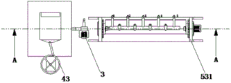
Referring to fig. 1 to 8, an embodiment of the present invention provides an automatic landscaping irrigation system, including a liquid storage tank 1, a mixing and stirring mechanism 2, an infusion pump 3, a chemical adding mechanism 4 and a greening spraying mechanism 5, wherein the greening spraying mechanism 5 is disposed beside the liquid storage tank 1, the chemical adding mechanism 4 is disposed at the top of the liquid storage tank 1, the infusion pump 3 is disposed between the greening spraying mechanism 5 and the liquid storage tank 1, the mixing and stirring mechanism 2 is disposed inside the liquid storage tank 1, the greening spraying mechanism 5 includes a swinging plate 51, a fixing plate 52, a crown spraying component 6, a root irrigation component 53 and two fixing seats 531 arranged at intervals, the crown spraying component 6 is disposed at the top of the swinging plate 51, the fixing plate 52 is horizontally disposed between the two fixing seats 531, each fixing seat 531 is provided with a mounting tube 532 rotationally connected thereto, the swinging plate 51 is arranged between two mounting cylinders 532, and each mounting cylinder 532 is fixedly connected with the swinging plate 51 through a bolt; the irrigation liquid introduced into the liquid storage tank 1 can be stirred and mixed through the mixing and stirring mechanism 2, the filter screen 22 can filter impurities, the rotating shaft 25 can vibrate the filter screen 22 in the rotating process to avoid the impurities from blocking the filter screen 22, the nutrient can be intermittently put into the liquid storage tank 1 through the medicament adding mechanism 4, the situation that the normal growth of plants is influenced due to too much or too little nutrient is avoided, the vibration operation of the medicament screening grid 461 can be realized, the situation that the normal putting amount of the nutrient is influenced due to the blocking of the medicament screening grid 461 is effectively avoided, the irrigation liquid can be regularly conveyed to a plurality of irrigation heads 54 through the tree root irrigation assembly 53, the irrigation operation on tree roots can be automatically realized through the device, the automation degree is higher, and the atomization spraying operation on the tree trunks and the tree crowns of the trees can be automatically realized through the tree crown spraying assembly 6, can automatically regulated atomizing nozzle 65 spray the angle, make atomizing nozzle 65 spray the operation to the plant in a distant place, improve this device's practicality.
Specifically, the crown spraying assembly 6 comprises a driving motor 61, a liquid conveying pipeline 62, a horizontally arranged transmission shaft 63 and a plurality of spraying pipelines 64 communicated with the liquid conveying pipeline 62, an atomizing nozzle 65 is arranged at a liquid outlet end of each spraying pipeline 64, a driven gear 66 is sleeved on each mounting cylinder 532, two ends of the transmission shaft 63 are rotatably connected with the two fixing seats 531 respectively, driving gears 67 are sleeved at two ends of the transmission shaft 63, the two driving gears 67 are respectively engaged with the two driven gears 66, the driving motor 61 is fixed on the side wall of one of the fixing seats 531, and an output end of the driving motor 61 is fixedly connected with an end of the transmission shaft 63; can realize carrying out the atomizing operation of spraying to the trunk and the crown of trees automatically through crown spray assembly 6, can automatically regulated atomizing nozzle 65's spray angle, make atomizing nozzle 65 can spray the operation to the plant in a distant place, the practicality of this device has been improved, driving motor 61 work can drive transmission shaft 63 and take place to rotate, make transmission shaft 63 can drive driving gear 67 and take place to rotate, make driving gear 67 can drive rather than the driven gear 66 of meshing take place to rotate, make two installation section of thick bamboo 532 can take place to rotate in step.
Specifically, the root irrigation assembly 53 comprises a connecting pipe 533 and a plurality of irrigation heads 54 horizontally arranged on the top of the fixing plate 52, the connecting pipe 533 is fixed on the fixing plate 52 through a pipe hoop, each connecting pipe 533 is provided with a plurality of liquid outlet pipes 55 communicated with the inside of the connecting pipe, each liquid outlet pipe 55 corresponds to one irrigation head 54, and a liquid delivery hose 56 is arranged between each liquid outlet pipe 55 and the corresponding irrigation head 54; can realize regularly carrying irrigation liquid to a plurality of irrigation head 54 through root irrigation subassembly 53, make this device can realize the irrigation operation to the root automatically, degree of automation is higher, and the worker installs irrigation head 54 in soil in advance, and transfer pump 3 can carry irrigation liquid to connecting tube 533 in through three-way pipe 13, makes every irrigation head 54 homoenergetic carry irrigation liquid to get into to soil in, accomplishes the irrigation operation to the root.
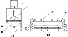
Specifically, a liquid outlet funnel 11 communicated with the inside of the liquid storage tank 1 is arranged at the bottom of the liquid storage tank 1, a liquid discharge pipeline 12 is arranged at the bottom of the liquid outlet funnel 11, the input end of the liquid infusion pump 3 is communicated with the liquid discharge pipeline 12, a three-way pipe 13 is arranged at the output end of the liquid infusion pump 3, the connecting pipeline 533, the liquid infusion pipeline 62 and the three-way pipe 13 are communicated through a hose, a first electromagnetic valve 14 is arranged on the liquid infusion pipeline 62, a second electromagnetic valve 15 is arranged on the connecting pipeline 533, a heater and a temperature sensor are arranged inside the liquid storage tank 1, a controller is arranged on the inner wall of the liquid storage tank 1, and the heater and the temperature sensor are electrically connected with the controller; the infusion pump 3 can convey the irrigation liquid to the connecting pipeline 533 through the three-way pipe 13, each irrigation head 54 can convey the irrigation liquid to enter soil, irrigation operation on tree roots is completed, the first electromagnetic valve 14 is used for adjusting the on-off of the infusion pipeline 62, and the second electromagnetic valve 15 is used for controlling the on-off of the connecting pipeline 533.
Specifically, the mixing and stirring mechanism 2 comprises a stirring and vibrating component 21 and a filter screen 22 horizontally arranged at the bottom end inside the liquid storage tank 1, wherein the stirring and vibrating component 21 is arranged above the filter screen 22, four support seats 23 distributed in a matrix form are arranged at the bottom of the filter screen 22, a vibrating spring 24 is arranged on each support seat 23, and the bottom of the filter screen 22 is fixedly connected with the four vibrating springs 24; can realize stirring the mixture to the irrigation liquid that lets in the deposit liquid case 1 through mixing rabbling mechanism 2 to filter screen 22 can realize the filtration operation to impurity, and axis of rotation 25 can realize the vibrations to filter screen 22 at the pivoted in-process, avoids impurity to cause filter screen 22's jam.
Specifically, the stirring and vibrating assembly 21 comprises a rotating shaft 25 and a stirring motor 26 which are horizontally arranged, two ends of the rotating shaft 25 are respectively rotatably connected with two sides of the liquid storage tank 1, an output end of the stirring motor 26 is fixedly connected with an end portion of the rotating shaft 25, a plurality of stirring blades 27 are sleeved on the rotating shaft 25, a U-shaped rod 271 is arranged at the middle section of the rotating shaft 25, a hinged seat 272 is arranged at the top of the filter screen 22, a transmission rod 28 hinged with the hinged seat 272 is arranged on the hinged seat 272, and an end portion of the transmission rod 28 is movably sleeved on the U-shaped rod 271; stirring motor 26 work can drive axis of rotation 25 and take place to rotate, make axis of rotation 25 can drive a plurality of stirring paddle leaf 27 and take place to rotate, make stirring paddle leaf 27 can realize stirring the mixed operation with the nutrient solution to deposit the inside irrigation liquid of liquid tank 1, axis of rotation 25 can drive U type pole 271 at the pivoted in-process and take place to rotate, make U type pole 271 can drive transfer line 28 and remove, make transfer line 28 can drive filter screen 22 and remove, realize filter screen 22's vibrations operation, effectively avoid filter screen 22 to take place to block up.
Specifically, the medicine adding mechanism 4 comprises a medicine storage box 41, a closing assembly 43 and a medicine sieving grid 461 horizontally arranged at the bottom end inside the medicine storage box 41, a medicine inlet nozzle 42 is arranged at the top of the medicine storage box 41, four connecting seats 471 distributed in a matrix manner are arranged inside the medicine storage box 41, a connecting spring 47 is arranged at the bottom of each connecting seat 471, and the top of the medicine sieving grid 461 is connected with the four connecting springs 47; can put in the nutrient to stock solution case 1 through the medicament interpolation mechanism 4 intermittent type, avoid the nutrient to put in too much or too little and influence the normal growth of plant to can realize the vibrations operation of sieve medicine grid 461, effectively avoid sieve medicine grid 461 to take place to block up and influence the normal volume of putting in of nutrient, connecting spring 47 is used for shaking and supporting sieve medicine grid 461.
Specifically, the sealing assembly 43 comprises a rotating motor 431, a sealing plate 432 in sliding fit with the medicine storage box 41, and a mounting seat 46 fixedly connected with the side wall of the liquid storage box 1, the rotating motor 431 is arranged at the bottom of the mounting seat 46, a driving wheel 433 is sleeved on the output end of the rotating motor 431, a rotating rod 434 hinged with the rotating wheel is sleeved on the rotating wheel, the end of the rotating rod 434 is hinged with the end of the sealing plate 432, a moving cam 435 is arranged at the top of the sealing plate 432, an extending strip 44 vertically arranged is arranged at the bottom of the medicine sieving grid 461, and a roller 45 matched with the moving cam 435 is arranged at the bottom of the extending strip 44; the work of rotating motor 431 can drive wheel 433 and take place to rotate, make drive wheel 433 can move rather than articulated dwang 434 drive, make dwang 434 can drive closure plate 432 horizontal migration, make closure plate 432 can intermittently realize opening or closing of depositing the medicine chest 41 bottom, closure plate 432 can drive movable cam 435 at the in-process that removes and move, make movable cam 435 can drive gyro wheel 45 and move, make extension strip 44 can drive sieve medicine grid 461 and shake, avoid the nutrient to block up sieve medicine grid 461.
The working principle of the invention is as follows: an operator puts irrigation liquid into the liquid storage box 1 and stores nutrient solution into the liquid storage box 41, when the temperature of water in the liquid storage box 1 is low due to cold weather, a temperature sensor sends an electric signal to a controller, the controller can send a signal to a heater to enable the heater to work to heat the irrigation liquid in the liquid storage box 1, the irrigation liquid can reach a proper temperature, the irrigation liquid introduced into the liquid storage box 1 can be stirred and mixed through a mixing and stirring mechanism 2, the filter screen 22 can filter impurities, the rotating shaft 25 can vibrate the filter screen 22 in the rotating process to avoid the blockage of the filter screen 22 caused by the impurities, the stirring motor 26 can work to drive the rotating shaft 25 to rotate, the rotating shaft 25 can drive a plurality of stirring blades 27 to rotate, and the stirring blades 27 can stir and mix the irrigation liquid and the nutrient solution in the liquid storage box 1, the rotating shaft 25 can drive the U-shaped rod 271 to rotate in the rotating process, so that the U-shaped rod 271 can drive the transmission rod 28 to move, the transmission rod 28 can drive the filter screen 22 to move, the vibration operation of the filter screen 22 is realized, the blockage of the filter screen 22 is effectively avoided, the nutrient can be intermittently put into the liquid storage tank 1 through the medicament adding mechanism 4, the influence of too much or too little nutrient on the normal growth of plants is avoided, the vibration operation of the medicament screening grid 461 can be realized, the influence of the blockage of the medicament screening grid 461 on the normal putting amount of the nutrient is effectively avoided, the rotating motor 431 can drive the driving wheel 433 to rotate, the driving wheel 433 can drive the rotating rod 434 hinged with the driving wheel 433 to move, the rotating rod 434 can drive the sealing plate 432 to move horizontally, and the sealing plate 432 can intermittently realize the opening or closing of the bottom of the medicament storage tank 41, the sealing plate 432 can drive the movable cam 435 to move in the moving process, the movable cam 435 can drive the roller 45 to move, the extension strip 44 can drive the medicine sieving grids 461 to vibrate, the medicine sieving grids 461 are prevented from being blocked by nutrients, the infusion pump 3 can pump out the irrigation liquid in the liquid storage tank 1 through the liquid discharge pipeline 12 and can respectively convey the irrigation liquid into the infusion pipeline 62 and the connecting pipeline (533) through the three-way pipe 13, the irrigation liquid can be conveyed to a plurality of irrigation heads (54) at regular time through the tree root irrigation component 53, the irrigation device can automatically realize the irrigation operation on tree roots, the automation degree is high, the infusion pump 3 can convey the irrigation liquid into the connecting pipeline (533) through the three-way pipe 13, and each irrigation head (54) can convey the irrigation liquid into soil to finish the irrigation operation on the tree roots, can realize atomizing the operation of spraying to the trunk and the crown of trees automatically through crown spray set 6, can automatically regulated atomizing nozzle 65's spray angle, make atomizing nozzle 65 can spray the operation to the plant in a distant place, the practicality of this device has been improved, driving motor 61 work can drive transmission shaft 63 and take place to rotate, make transmission shaft 63 can drive driving gear 67 and take place to rotate, make driving gear 67 can drive rather than the driven gear 66 of meshing take place to rotate, make two installation section of thick bamboo 532 can take place to rotate in step, realize the rotation of swinging plate 51, thereby adjust atomizing nozzle 65's spray angle.
Finally, it should be noted that: the above embodiments are only used to illustrate the technical solution of the present invention, and not to limit the same; while the invention has been described in detail and with reference to the foregoing embodiments, it will be understood by those skilled in the art that: the technical solutions described in the foregoing embodiments may still be modified, or some or all of the technical features may be equivalently replaced; and the modifications or the substitutions do not make the essence of the corresponding technical solutions depart from the scope of the technical solutions of the embodiments of the present invention.