Background
Along with the development of social economy, the building technology is rapidly developed, the height of the building is gradually increased, and along with the increase of the height of the building, more external influence factors to the building need to be considered, wherein the vibration-proof and vibration-damping technology is one of the technologies, for example, a high-rise building is shaken in high altitude due to strong wind and typhoon, and vibration transmitted from the underground during earthquake can cause great damage to the building.
Therefore, the patent with application number 201610857733.6 discloses a bottom surface integral sliding friction pendulum type vibration isolation layer, which comprises a bottom surface spherical shell and an upper spherical frame, wherein: the lower side of the bottom spherical shell is integrally cast with a concrete foundation or a lower layer structure, and the upper surface is a large-span circular arc spherical surface with large curvature radius; upper portion spherical frame is by a plurality of sliders, even roof beam, the heel post, connecting element connects and forms, connecting element lower part and slider welding, the connecting element lateral part is connected with even roof beam, connecting element upper portion passes through the heel post and links to each other with superstructure, the upper surface overlap joint of slider and bottom surface spherical shell, and the slider lower surface keeps unanimous with the convex sphere in corresponding position, avoid appearing the point contact, this whole sliding friction pendulum-type shock insulation layer in bottom surface passes through to be connected between the slider and forms slidable spherical frame, form whole sliding friction pendulum-type layer in bottom surface with the combination of bottom surface spherical shell, bottom surface spherical shell span is very big, the horizontal direction is allowed to warp and is far greater than the shock insulation support, can satisfy shock insulation layer horizontal deformation under the super large: (1) the bottom surface integral sliding friction pendulum type shock insulation layer only carries out vibration damping and vibration prevention through a simple shock insulation layer on one side, and the achieved vibration prevention effect is not good enough; (2) when the building vibrates, the restoring capability of the bottom surface integral sliding friction pendulum type shock insulation layer is not good enough, the building can not be restored to the original state in time, and the shock insulation layer is easy to be damaged by continuous vibration and loses the shock insulation effect.
Disclosure of Invention
In order to overcome the technical problems, the invention aims to provide a friction sliding bearing seat vibration damping structure between the ground and a building, which comprises the following components: (1) the vibration reduction structure of the friction sliding bearing seat is that a bearing base which can support the weight of a building body and a sliding base which has free deformation capability in the horizontal direction are arranged at the lower part of the building, the horizontal deformation generated during vibration is concentrated on the whole vibration reduction device, the upper building is prevented from being damaged, the energy generated by vibration is absorbed by a damper, laminated rubber and an elastic layer, the distortion and bending degree of the building are greatly reduced, the vibration period of the building is prolonged, the damping ratio is increased, and the energy released by the vibration to the building is consumed, the shock-proof structure reduces the attack of force generated by vibration on a building, converts the swing of the building during vibration into the transverse displacement of the building relative to the ground through the damper, the laminated rubber and the elastic layer, and absorbs seismic energy through the damper, the laminated rubber and the elastic layer, so that the distortion and the bending of the building can be greatly reduced, the swinging degree can also be obviously reduced, and the damage of the structure and equipment is reduced; (2) through at first mounting panel, the board that resets is installed at second mounting panel both ends, the board that resets passes through the pneumatic cylinder and damping spring is connected anti-vibration device and antivibration groove both sides, during the building vibration, when the power that produces makes whole antivibration device remove, through the compression of pneumatic cylinder and damping spring, produce a drive force and make the building to the opposite direction swing, make the building rock the power of production and offset by the drive force, make the amplitude of rocking reduce widely, the building is pushed back original direction, when having solved at the building emergence vibration, the recovery ability on current bottom surface whole sliding friction shock insulation pendulum type layer is not good enough, can not in time make the building resume original state, make this shock insulation layer easily destroyed by continuous vibration, lose the problem of its shock insulation effect.
The purpose of the invention can be realized by the following technical scheme:
a friction sliding bearing seat vibration damping structure between the ground and a building comprises a bearing base and a vibration damping device, wherein a sliding base is arranged at the top of the bearing base, a vibration damping groove is formed in the middle of the top of the bearing base, and the vibration damping device is arranged in the vibration damping groove;
the vibration-proof device comprises a sliding base, a vibration-proof groove, a plurality of vibration-proof grooves, a plurality of first arc-proof grooves, a plurality of second arc-proof grooves, a plurality of first rolling balls, a plurality of supporting seats and a plurality of supporting seats, wherein the plurality of second arc-proof grooves are respectively arranged on two sides of the bottom of the sliding base;
the two sides of the bottom of the first mounting plate are provided with a plurality of dampers, the bottom of each damper is provided with an upper wing plate, the bottom of each upper wing plate is provided with laminated rubber, the bottom of each laminated rubber is provided with a lower wing plate, and the lower wing plates are all connected to the top of the second mounting plate through bolts;
the two ends of the first mounting plate are both connected with reset plates, the bottoms of the reset plates are connected to one end of the second mounting plate, hydraulic cylinders are mounted at the top and the bottom of one side of the reset plates, which is far away from the first mounting plate, and one ends of the hydraulic cylinders, which are far away from the reset plates, are connected to the inner wall of the anti-vibration groove, and the anti-vibration groove is connected to the middle part of the reset plates through damping springs;
a plurality of upper bases are installed to second mounting panel bottom, go up the base bottom and seted up curved spout district, slidable mounting has the slide in the spout district, slide bottom central point puts and installs the undersetting, the elastic layer is installed to the undersetting bottom, the elastic layer both ends are installed respectively in mounting groove inner wall both sides, the sliding sleeve is installed to the mounting groove bottom.
As a further scheme of the invention: the elastic layer comprises a plurality of spring steel plates, and is a plurality of spring steel plate all is the arc, and is a plurality of spring steel plate increases length from last to down in proper order, the attenuator comprises a plurality of pillars, the pillar comprises spring steel matter.
As a further scheme of the invention: the laminated rubber is formed by alternately laminating a plurality of rubber layers and steel plate layers, and the steel plate layers are made of carbon steel.
As a further scheme of the invention: a plurality of pulleys are installed on two sides of the bottom of the sliding sleeve, a sliding rail is installed inside the sliding sleeve in a sliding mode, and the sliding rail is installed on the inner wall of the bottom of the anti-vibration groove.
As a further scheme of the invention: the top of the sliding base is provided with a building, and the bottom of the bearing base is arranged on the ground.
As a further scheme of the invention: the working process of the damping structure of the friction sliding bearing seat is as follows:
the method comprises the following steps: when a building shakes due to high-altitude strong wind and typhoon blowing, vibration is transmitted from the top end to the bottom end of the building and transmitted to the sliding base to drive the sliding base to shake left and right, the first arc-shaped groove at the bottom of the sliding base slides on the top of the second rolling ball, the second arc-shaped groove slides on the lower arc-shaped groove through the first rolling ball to drive the sliding base to do circular sliding friction motion on the bearing base, most of vibration is eliminated in a sliding friction mode, part of vibration continues to be transmitted downwards to drive the damper and the laminated rubber to deform, and because deformation needs force action, the force generating deformation in the deformation process is generated by vibration driving, so that the vibration is further consumed, the vibration isolating device is driven to do circular sliding friction motion by moving the sliding sleeve on the sliding rail, and the vibration generated at the top end of the building is eliminated;
step two: when the vibration generated by earthquake is transmitted from the ground bottom to the ground, when the vibration is transmitted to the bottom of the bearing base, the bearing base is pushed to rise, the vibration amplitude is reduced through the bending deformation of a plurality of spring steel plates on the elastic layer, the sliding plate at the top of the lower support is swung leftwards and rightwards in the sliding groove area on the upper base, the swing of the building during the vibration is converted into the transverse displacement of the building relative to the ground, the rest vibration is continuously transmitted upwards to drive the damper and the laminated rubber to deform, because the deformation needs the action of force, the deformation force is generated by the vibration in the deformation process, so the vibration is further consumed, the rest vibration is continuously transmitted upwards to drive the sliding base to swing leftwards and rightwards, the first arc-shaped groove at the bottom of the sliding base slides at the top of the second rolling ball, the second arc-shaped groove slides on the lower arc-shaped groove through the first rolling ball, so that the building on the ground does the circular sliding friction motion, vibrations generated from the ground are eliminated;
step three: when the whole anti-vibration device moves left and right, the hydraulic cylinder and the damping spring are compressed by the force generated by shaking the building, and the hydraulic cylinder and the damping spring generate the driving force after being compressed, so that the building swings in opposite directions, the force generated by shaking the building is offset by the driving force, the shaking amplitude is greatly reduced, and the building restores to the original position.
The invention has the beneficial effects that:
(1) according to the friction sliding bearing seat vibration damping structure between the ground and a building, the first arc-shaped groove at the bottom of the sliding base slides on the top of the second rolling ball, the second arc-shaped groove slides on the lower arc-shaped groove through the first rolling ball, and the sliding sleeve moves on the sliding rail through sliding, so that the sliding base is driven to do circulating sliding friction motion on the bearing base, the whole vibration damping device does circulating sliding friction motion, the friction sliding bearing seat vibration damping structure is provided with the bearing base which can support the weight of the building body and the sliding base which has free deformation capability in the horizontal direction at the lower part of the building, horizontal deformation generated during vibration is concentrated on the whole vibration damping device, damage of an upper building is avoided, and the vibration damping effect of the structure is good;
the energy generated by vibration is absorbed by the deformation of the damper, the laminated rubber and the elastic layer, so that the distortion and bending degree of a building are greatly reduced, the vibration period of the building is prolonged, the damping ratio is increased, the energy released by the vibration to the building is consumed, the attack of the force generated by the vibration to the building is reduced, the swinging of the building during the vibration is converted into the transverse displacement of the building relative to the ground by the damper, the laminated rubber and the elastic layer, the energy of the vibration is absorbed by the damper, the laminated rubber and the elastic layer, so that the distortion and the bending of the building are greatly reduced, the swinging degree is obviously reduced, the damage of structures and equipment is reduced, the vibration damping structure of the friction sliding bearing seat separates the ground of the vibration, the vibration strength is reduced, and the vibration-proof effect of the structure is further improved;
(2) the invention relates to a vibration damping structure of a friction sliding bearing seat between the ground and a building, by arranging the reset plates at the two ends of the first mounting plate and the second mounting plate and connecting the anti-vibration device with the two sides of the anti-vibration groove through the hydraulic cylinder and the damping spring, when the building vibrates, the force generated by the building drives the whole anti-vibration device to move left and right, through the compression of the hydraulic cylinder and the damping spring, a pushing force is generated to lead the building to swing towards the opposite direction, the force generated by the shaking of the building is counteracted by the pushing force, the shaking amplitude is greatly reduced, the building is pushed back to the original direction, the pushing force can be generated as long as the hydraulic cylinder and the damping spring are compressed, so that the building can be restored to the original state in time, make this friction slip bearing seat damping structure's antivibration effectual, make this structure antivibration continuation strengthen simultaneously.
Detailed Description
The technical solutions in the embodiments of the present invention will be clearly and completely described below with reference to the embodiments of the present invention, and it is obvious that the described embodiments are only a part of the embodiments of the present invention, and not all of the embodiments. All other embodiments, which can be derived by a person skilled in the art from the embodiments given herein without making any creative effort, shall fall within the protection scope of the present invention.
Example 1:
referring to fig. 1-10, the present embodiment is a friction sliding load-bearing seat vibration damping structure between the ground and a building, including a load-bearing base 102 and a vibration damping device 104, wherein a sliding base 101 is disposed on the top of the load-bearing base 102, a vibration damping slot 103 is disposed in the middle of the top of the load-bearing base 102, and the vibration damping device 104 is installed inside the vibration damping slot 103;
a plurality of second arc-shaped grooves 8 are respectively arranged on two sides of the bottom of the sliding base 101, a lower arc-shaped groove 10 is movably arranged at the bottom of the second arc-shaped groove 8, a first rolling ball 9 is arranged between the second arc-shaped groove 8 and the lower arc-shaped groove 10, the bottoms of the lower arc-shaped grooves 10 on two sides are respectively connected to two sides of the vibration-proof groove 103, a plurality of first arc-shaped grooves 4 are arranged at the middle position of the bottom of the sliding base 101, the bottom of each first arc-shaped groove 4 is connected with a second rolling ball 13 in a cambered surface mode, a sleeve 12 is sleeved outside each second rolling ball 13, a supporting seat 11 is arranged at the bottom of each sleeve 12, the bottoms of a plurality of supporting seats 11 are respectively connected to the top of the first mounting plate 3, the sliding base 101 slides on the tops of the second rolling balls 13 through the first arc-shaped grooves 4 at the bottom of the sliding base 101, the second arc, so that the whole anti-vibration device 104 performs a circular sliding friction motion;
the two sides of the bottom of the first mounting plate 3 are provided with a plurality of dampers 14, the bottom of each damper 14 is provided with an upper wing plate 15, the bottom of each upper wing plate 15 is provided with a laminated rubber 2, the bottom of each laminated rubber 2 is provided with a lower wing plate 16, the lower wing plates 16 are all connected to the top of the second mounting plate 5 through bolts, the dampers 14 and the laminated rubbers 2 deform to absorb energy generated by vibration, so that the distortion and bending degree of the building 100 are greatly reduced, the vibration period of the building 100 is prolonged, the damping ratio is increased, energy released by the vibration to the building 100 is consumed, and the attack of force generated by the vibration to the building 100 is reduced;
the two ends of the first mounting plate 3 are both connected with a reset plate 1, the bottom of the reset plate 1 is connected to one end of the second mounting plate 5, the top and the bottom of one side of the reset plates 1 far away from the first mounting plate 3 are both provided with a hydraulic cylinder 19, one end of the hydraulic cylinder 19, which is far away from the reset plate 1, is connected to the inner wall of the vibration-proof groove 103, the vibration-proof groove 103 is connected to the middle part of the reset plate 1 through the vibration-proof spring 20, when the building 100 vibrates, the generated force makes the whole vibration-proof device 104 move left and right, by the compression of the hydraulic cylinder 19 and the damper spring 20, an urging force is generated to swing the building 100 in the opposite direction, the force generated by the shaking of the building 100 is offset by the pushing force, so that the shaking amplitude is greatly reduced, the building 100 is pushed back to the original direction, and the building 100 can be timely restored to the original state by generating the pushing force as long as the hydraulic cylinder 19 and the damping spring 20 are compressed;
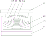
a plurality of last bases 22 are installed to 5 bottoms of second mounting panel, go up curved spout district 23 seted up to base 22 bottom, slidable mounting has slide 24 in the spout district 23, 24 bottom central points of slide put and install undersetting 25, elastic layer 6 is installed to undersetting 25 bottom, install respectively in mounting groove 21 inner wall both sides at 6 both ends of elastic layer, sliding sleeve 7 is installed to mounting groove 21 bottom, and when vibration transmission to bearing base 102 bottom, promote bearing base 102 and rise, reduce the vibration range through the crooked deformation of a plurality of spring steel sheet 61 on the elastic layer 6, rocks about slide 24 through undersetting 25 top on last base 22 in spout district 23 to and sliding sleeve 7 slides on slide rail 26, and the swing of building 100 converts building 100 to the lateral displacement of ground 105 when will vibrating.
Elastic layer 6 comprises a plurality of spring steel sheet 61, and is a plurality of spring steel sheet 61 all is the arc, and is a plurality of spring steel sheet 61 increases in proper order from last length down, attenuator 14 comprises a plurality of pillars, the pillar comprises spring steel matter.
The laminated rubber 2 is formed by alternately laminating a plurality of rubber layers 17 and steel plate layers 18, and the steel plate layers 18 are made of carbon steel.
A plurality of pulleys 27 are installed on both sides of the bottom of the sliding sleeve 7, a sliding rail 26 is installed inside the sliding sleeve 7 in a sliding mode, and the sliding rail 26 is installed on the inner wall of the bottom of the anti-vibration groove 103.
The building 100 is arranged on the top of the sliding base 101, and the bottom of the bearing base 102 is arranged on the ground 105.
Referring to fig. 1-10, the operation of the vibration damping structure of the friction sliding load-bearing seat between the ground and the building according to the present embodiment is as follows:
the method comprises the following steps: when the building 100 shakes due to high-altitude strong wind and typhoon blowing, vibration is transmitted from the top to the bottom of the building 100 and transmitted to the sliding base 101 to drive the sliding base 101 to shake left and right, the first arc-shaped groove 4 at the bottom of the sliding base 101 slides on the top of the second rolling ball 13, the second arc-shaped groove 8 slides on the lower arc-shaped groove 10 through the first rolling ball 9 to drive the sliding base 101 to do circular sliding friction motion on the bearing base 102, most of the vibration is eliminated through the sliding friction mode, part of the vibration continues to be transmitted downwards to drive the damper 14 and the laminated rubber 2 to deform, and because of the action of deformation required force, the force causing the deformation is generated by the vibration during the deformation process, so that the vibration is further consumed, the sliding sleeve 7 moves on the sliding rail 26 to drive the whole anti-vibration device 104 to do circular sliding friction motion, and the vibration transmitted from the top end to the bottom of the building 100 is eliminated;
step two: when the vibration generated by earthquake is transmitted from the ground bottom to the ground 105, when the vibration is transmitted to the bottom of the bearing base 102, the bearing base 102 is pushed to rise, the vibration amplitude is reduced through the bending deformation of the plurality of spring steel plates 61 on the elastic layer 6, the sliding plate 24 at the top of the lower support 25 swings left and right in the sliding groove area 23 on the upper base 22, the swing of the building 100 during the vibration is converted into the transverse displacement of the building 100 relative to the ground 105, the rest vibration is continuously transmitted upwards to drive the damper 14 and the laminated rubber 2 to deform, because of the action of deformation requirement, the force generating deformation is driven by the vibration in the deformation process, so the vibration is further consumed, the rest vibration is continuously transmitted upwards to drive the sliding base 101 to swing left and right, the first arc-shaped groove 4 at the bottom of the sliding base 101 slides at the top of the second rolling ball 13, the second arc-shaped groove 8 slides on the lower arc-shaped groove 10 through the first rolling ball 9, the building 100 on the ground 105 is made to make a circular sliding friction movement on the bearing base 102 through the sliding base 101, and the vibration generated by the underground is eliminated;
step three: when the whole anti-vibration device 104 moves left and right, the hydraulic cylinder 19 and the damping spring 20 are compressed by the force generated by the shaking of the building 100, and the pushing force generated by the compressed hydraulic cylinder 19 and the compressed damping spring 20 causes the building 100 to swing in the opposite direction, so that the force generated by the shaking of the building 100 is offset by the pushing force, the amplitude of the shaking is greatly reduced, and the building 100 restores to the original position.
In the description herein, references to the description of "one embodiment," "an example," "a specific example" or the like are intended to mean that a particular feature, structure, material, or characteristic described in connection with the embodiment or example is included in at least one embodiment or example of the invention. In this specification, the schematic representations of the terms used above do not necessarily refer to the same embodiment or example. Furthermore, the particular features, structures, materials, or characteristics described may be combined in any suitable manner in any one or more embodiments or examples.
The foregoing is illustrative and explanatory only and is not intended to be exhaustive or to limit the invention to the precise embodiments described, and various modifications, additions, and substitutions may be made by those skilled in the art without departing from the scope of the invention or exceeding the scope of the claims.