CN110817485B - Anti-unbalance-loading system and method for throwing type unloading of railway loading station - Google Patents
Anti-unbalance-loading system and method for throwing type unloading of railway loading station Download PDFInfo
- Publication number
- CN110817485B CN110817485B CN201911092384.3A CN201911092384A CN110817485B CN 110817485 B CN110817485 B CN 110817485B CN 201911092384 A CN201911092384 A CN 201911092384A CN 110817485 B CN110817485 B CN 110817485B
- Authority
- CN
- China
- Prior art keywords
- carriage
- loading
- chute
- speed
- detector
- Prior art date
- Legal status (The legal status is an assumption and is not a legal conclusion. Google has not performed a legal analysis and makes no representation as to the accuracy of the status listed.)
- Active
Links
Images


Classifications
-
- B—PERFORMING OPERATIONS; TRANSPORTING
- B65—CONVEYING; PACKING; STORING; HANDLING THIN OR FILAMENTARY MATERIAL
- B65G—TRANSPORT OR STORAGE DEVICES, e.g. CONVEYORS FOR LOADING OR TIPPING, SHOP CONVEYOR SYSTEMS OR PNEUMATIC TUBE CONVEYORS
- B65G67/00—Loading or unloading vehicles
- B65G67/02—Loading or unloading land vehicles
- B65G67/04—Loading land vehicles
- B65G67/06—Feeding articles or materials from bunkers or tunnels
-
- B—PERFORMING OPERATIONS; TRANSPORTING
- B65—CONVEYING; PACKING; STORING; HANDLING THIN OR FILAMENTARY MATERIAL
- B65G—TRANSPORT OR STORAGE DEVICES, e.g. CONVEYORS FOR LOADING OR TIPPING, SHOP CONVEYOR SYSTEMS OR PNEUMATIC TUBE CONVEYORS
- B65G69/00—Auxiliary measures taken, or devices used, in connection with loading or unloading
- B65G69/04—Spreading out the materials conveyed over the whole surface to be loaded; Trimming heaps of loose materials
-
- B—PERFORMING OPERATIONS; TRANSPORTING
- B65—CONVEYING; PACKING; STORING; HANDLING THIN OR FILAMENTARY MATERIAL
- B65G—TRANSPORT OR STORAGE DEVICES, e.g. CONVEYORS FOR LOADING OR TIPPING, SHOP CONVEYOR SYSTEMS OR PNEUMATIC TUBE CONVEYORS
- B65G2201/00—Indexing codes relating to handling devices, e.g. conveyors, characterised by the type of product or load being conveyed or handled
- B65G2201/04—Bulk
- B65G2201/045—Sand, soil and mineral ore
Abstract
The invention relates to an anti-unbalance loading system and method for throwing type unloading of a railway loading station, which comprises the following steps: the device comprises a loading station, a discharge gate, a carriage speed detector, a carriage position detector, a chute material storage detector, a gate position detector, an anti-unbalance-loading controller, an expert database, a train number reader, a train speed controller, a discharge chute controller, a discharge gate controller and a loading station upper computer. The ideal balanced loading state is obtained by calculating the loading carriage and the amount of the goods in advance, loading is carried out according to the ideal state during loading, the loading state of the carriage is continuously monitored, and the loading state is adjusted to be close to the ideal state as far as possible until loading is finished. The invention minimizes the possibility of unbalance loading, realizes full automation of loading, and reduces the risk of manual high-intensity operation and safety problem of the flatcar after loading.
Description
Technical Field
The invention relates to an anti-unbalance loading system and method for throwing type unloading of a loading station, in particular to an automatic additional system and method for electromechanical automatic loading equipment, and an additional system and method for an automatic loading station of bulk goods.
Background
The fast quantitative loading has three unloading modes, including flood type, flow guiding type and throwing type, aiming at the characteristics of bulk cargo. The flood flow mainly aims at loading coal materials. The material has small specific gravity, and the carriage is filled with the material under the action of the chute after the material is unloaded. The diversion type discharging device is mainly used for discharging grain materials, realizes the distribution control of the materials by utilizing the chute, and mainly aims to reduce the damage rate of the grains in the discharging process and play a role in stopping damage. The last type of throw-away is mainly directed to materials with a high specific gravity, such as iron pellets, iron ore. The materials have high relative density, and in the process of unloading the materials to a general open wagon of a train, because the volume is relatively small, the materials cannot fill the carriage, the distance from the upper edge of the carriage after the materials are unloaded is far, and meanwhile, the chute is forbidden to excessively go deep into the carriage to avoid collision, so that the materials are thrown by adopting a swing type chute with a controllable gate.
Among the three discharging modes, the throwing discharging mode has the greatest control difficulty and is most easy to form unbalance loading. Because the materials are thrown and discharged into the carriage, the vehicle is in a moving state in the throwing process, and the discharging control time has strict requirements for avoiding the materials from being thrown outwards; meanwhile, the flow rate of the materials during unloading needs to be strictly controlled, so that the materials are uniformly paved at the bottom of the carriage. The unbalance loading mentioned here means that the cargo is not uniform in the front and rear, but not in the left and right, in the vehicle compartment. In general, the positions of the railway and the loading station are relatively fixed, namely the loading chute is stably kept right above the carriage, and materials are basically positioned on the bilateral symmetry axis of the carriage when being thrown into the carriage, so that the lateral deviation is small. The unbalance loading of bulk cargo in a train carriage is mainly reflected in the unevenness of the cargo in the front and the back of the carriage. The reason for this is that the remaining goods and the empty parts of the carriages cannot be well matched in the process of unloading the goods, that is, when a certain time of loading a carriage arrives, it is found that the empty parts of the carriages are not enough to hold the remaining goods according to the current unloading amount, or on the contrary, the remaining parts of the carriages are too much and the remaining goods are not enough to fill the spaces, so that the unloading amount can be only increased or decreased, and the loading amount distribution at the front and the rear of the carriages is not uniform. This uneven loading of the cargo on the front and back of a section of the car is very detrimental. In recent years, after the speed of the railway is greatly increased, the phenomenon of irregular loading of the railway occurs due to inaccurate loading, uneven loading, shifting of goods during transportation and the like. Particularly, under the limit of objective conditions and the driving of economic benefits, the overload and unbalance loading phenomena of the railway freight car are very serious, the vehicle is seriously damaged, the service life is greatly shortened, and even the driving safety is endangered. The technical state of the train and the transportation safety of the train are directly threatened by vehicle unbalance loading, and if the train is in the running condition for a long time, the wheels and axles of the train are stressed unevenly, the train is in a fatigue state for a long time, and accidents such as axle breakage, axle cutting, rail climbing, train overturning and the like can happen. The existing method for solving the problems is to carry out operation through manual experience accumulation, but the manual operation has the defects of inaccuracy and difficult consistency of unbalance loading prevention effects caused by different experiences of each person, so the effect is not satisfactory. In order to solve the problem of unbalanced loading of the loaded car, the goods in the carriage need to be uniformly adjusted by manpower or machinery, and more manpower and material resources need to be spent in the uniform process.
Disclosure of Invention
In order to overcome the problems in the prior art, the invention provides an anti-unbalance loading system and method for the throwing type unloading of a loading station. The system and the method can automatically disperse the goods in the whole carriage uniformly by identifying various carriages and formulating a strategy in advance and continuously adjusting in the loading process, thereby avoiding the unbalanced loading of the loading.
The purpose of the invention is realized as follows: the utility model provides a loading station formula of shedding is unloaded prevents unbalance loading system, includes: the device comprises a discharging chute, a carriage speed detector, a carriage position detector, a chute material stock detector and a gate position detector, wherein the discharging chute is provided with a discharging gate, the carriage speed detector and the carriage position detector are arranged on a steel structure frame of the loading station; the device comprises a carriage speed detector, a carriage position detector, a chute material stock detector and a gate position detector, wherein the carriage speed detector, the carriage position detector, the chute material stock detector and the gate position detector are connected with an anti-unbalance loading controller, and the anti-unbalance loading controller is also connected with an expert database and a train number reader and is connected with a train speed controller, a discharging chute controller, a discharging gate controller and a loading station upper computer.
Furthermore, the car speed detector is a Doppler speed measuring radar arranged on one side of the rail.
Further, the car position detector is a measuring light curtain sensor arranged on two sides of the rail.
Further, the chute material stock detector comprises: the device comprises a force sensor arranged at the joint of a material port flange above a discharging chute and a steel structure frame and a force sensor arranged at the position of a winch lifting hook at the lower part of the discharging chute.
Furthermore, the car number reader is an electronic tag identification device.
An anti-unbalance loading method for the throw-type unloading of a loading station by using the system comprises the following steps:
step 1, compartment identification: the car number reader identifies the carriage close to the entrance of the loading station to determine the type of the carriage, and informs the anti-unbalance loading controller of the identification result;
the following steps 2, 3 and 4 are carried out simultaneously;
step 4, determining the motion parameters of the carriage: detecting the movement speed and position of the current carriage through a carriage speed detector and a carriage position detector;

Wherein:N 0 the total mass of materials loaded into the current loading compartment;Vthe current running speed of the train;L 0 representing the total length of the current loaded carriage;
and 7, starting unloading: the carriage position detector detects that the carriage reaches the loading position, the discharging chute is put down, the discharging gate is opened, meanwhile, the chute material storage detector starts to monitor the material flow in the chute, the carriage speed detector monitors the speed of the carriage, and the carriage position detector monitors the relative position of the carriage and the chute;
step 8, unloading monitoring: the position and speed of the car movement are monitored by a car position detector and a car speed detector to determine whether the loading process meets two loading conditions:


wherein:Tfor the complete discharge time of the currently loaded car,mis the added value of the mass of the materials in the carriage in unit time,vis an increased value of the car motion per unit time, i.e. the current speed of the car;
monitoring the current position of the carriage through a carriage position detector, calculating the loaded amount and the unloaded amount according to the current position, and judging whether the current carriage is uniformly loaded according to the current loaded amount and the unloaded amount;
simultaneously monitoring the speed of the carriagevWhether or not at the maximum allowable vehicle speedV MAX And minimum allowable vehicle speedV MIN In case of exceedingV MAX >v>V MIN The train speed is controlled by a train speed controllerVGo back toV MAX >v>V MIN A range of (d);
material flow in chute by chute material stock detectorQMonitoring is carried out ifQ>Q set The opening degree of the discharging gate is reduced, if soQ set >QThe opening degree of the discharging gate is increased; if it is notQ set =QMaintaining the opening degree of the discharge gate;
and 9, ending: the chute is lifted to finish unloading and enters the next carriage for loading.
Further, the vehicle speed monitoring in step 4 is as follows: the Doppler speed radar is arranged at a distance of 1m from the carriage and faces to a detection area, and the irradiation direction of the radar and the advancing direction of the train formαAngle, vehicle speed is:
v =v’cosα
wherein:v' is the velocity measured by the doppler velocimetry radar.
Further, the chute material stock detector in the step 8 monitors the material weight calculation mode of the material flow in the chute:
total weight of material in chuteG:
G = k 1 G 1 + k 2 G 2 cos θ
Wherein:G 1the weight is borne by a flange of a discharging chute material port;G 2is the tension of the steel wire rope at the hook of the discharging chute;θis the included angle between the discharge chute cylinder and the vertical direction;k 1the stress correction coefficient is applied to the flange of the discharging chute material port;k 2is the stress correction coefficient at the hook of the discharging chute.
Further, the material flow passing through the gate is controlled by the gate opening degree in the step 8QThe calculation of (2):

wherein:iis the number of sampling times (i=1,2,……,n);F(i) To sampleiThe chute gravity in time;F(i+ 1) is a sampleiChute gravity at + 1;tis the sampling period.
Further, the process for controlling the material flow further comprises: at the beginning and end of loading a section of carriage, the flow is doubled.
The invention has the following beneficial effects: the ideal balanced loading state is obtained by calculating the loading carriage and the amount of the goods in advance, loading is carried out according to the ideal state during loading, the loading state of the carriage is continuously monitored, and the loading state is adjusted to be close to the ideal state as far as possible until loading is finished. The invention minimizes the possibility of unbalance loading, realizes full automation of loading, particularly meets the requirement of unbalance loading prevention, solves the problems in the loading process, and reduces the risks of manual high-intensity operation and safety problems of the flatcar after loading.
Drawings
The invention is further illustrated by the following figures and examples.
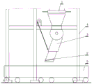
FIG. 1 is a schematic diagram of the position of the system in a loading station according to an embodiment of the invention;
FIG. 2 is a functional block diagram of the system according to one embodiment of the present invention;
FIG. 3 is a schematic diagram of an installation of a Doppler radar according to a second embodiment of the invention;
FIG. 4 is a schematic diagram of grating groups installed on two sides of a railway according to a third embodiment of the present invention;
figure 5 is a schematic view of a sensor mounting of a discharge chute according to a fourth embodiment of the present invention;
FIG. 6 is a block flow diagram of a method according to a sixth embodiment of the invention;
FIG. 7 is a timing diagram of the discharge gate and flow rate in accordance with the tenth embodiment of the present invention.
Detailed Description
The first embodiment is as follows:
the embodiment is an unbalance loading preventing system for throwing type discharging of a loading station, and is shown in figures 1 and 2. The embodiment comprises the following steps: the device comprises a discharging gate 1 of a loading station, a discharging chute 3 with a discharging gate 2, a carriage speed detector and a carriage position detector which are arranged on a steel structure frame 4 of the loading station, a chute material stock detector arranged on the discharging chute and a gate position detector arranged on the discharging gate; the device comprises a carriage speed detector, a carriage position detector, a chute material stock detector and a gate position detector, wherein the carriage speed detector, the carriage position detector, the chute material stock detector and the gate position detector are connected with an anti-unbalance loading controller, and the anti-unbalance loading controller is also connected with an expert database and a train number reader and is connected with a train speed controller, a discharging chute controller, a discharging gate controller and a loading station upper computer.
The system described in this embodiment is directed to a loading station for drop-off dumping, so that the lower outlet is some distance away from the car 5 when the chute is lowered, as shown in figure 1.
The system described in this embodiment is integrated with a loading station, the discharge gate and the discharge chute are components of the loading station, and other components of the system described in this embodiment are mainly various sensors and electronic digital processing devices. The sensors and the electronic digital processing device are integrated with the loading station.
The discharging gate is a discharging gate of a buffer bin of the loading station, and the discharging gate is mainly used for being matched with the discharging gate of the buffer bin so as to keep the material in the chute not to be too much or too little in the discharging process. The discharging gate is controlled by a control system (an upper computer of the loading station) of the loading station.
The discharging chute is provided with a loading station and comprises a buffer hopper, a winch, a hydraulic opening and closing discharging gate and the like. The discharge chute described in this embodiment is primarily referred to as a swing chute. The swing position of the swing chute is controlled by a winch. The flow of the discharged material is controlled by the opening degree of the discharging gate. The carriage is arranged below the chute, and the outlet of the discharging chute is higher than the carriage and keeps a certain distance from the upper opening of the carriage due to the throwing type discharging. The carriage travels in a horizontal direction below the chute. The discharge chute is controlled by the control system of the loading station and the system of the embodiment.
A schematic block diagram of the system according to this embodiment is shown in fig. 2. The embodiment mainly comprises an input reading part, an expert database, a control system and an output control part. The input part mainly reads the speed and position information of the carriage, the stock information of the chutes of the loading station, the position information of the discharging flashboards and the like. The car number reader reads the car number of the car, and then knows the car model, such as C70, C80, and the like. And the expert database judges the information of the height, the length and the like of the carriage according to the type of the carriage and submits the information to the anti-unbalance controller. The anti-unbalance loading controller analyzes the shape of the carriage and the amount of the goods to be loaded by the carriage loaded currently to determine the ideal unloading flow. When the carriage is loaded, the anti-unbalance-loading controller requires the train to keep moving within a speed range according to the obtained information, and simultaneously controls the swing angle of the discharging chute and the opening degree of the gate on the chute, so that the range and the flow rate of the discharging are controlled, the full automation of the throwing type discharging is realized, the throwing process of the whole loading is uniform and stable, and the unbalance-loading problem is avoided.
The carriage speed detector is used for detecting the speed of the current loading carriage. This speed is important in relation to whether the loading is uniform or not. There are various means for detecting the speed of the train, such as installing a doppler radar for measuring the speed on the side of the road where the train passes through, or other types of speed measuring sensors.
The function of the carriage position detector is to detect the loading position of the current loading vehicle, or the relative position of the chute and the carriage. This position shows the current status of the cargo load, e.g. quarter, half, etc. loaded. The detection position can be selected by various means, such as photoelectric recognition by adopting a grating arranged on the road side, or installing a pressure sensor on a track, or arranging a marker which can be subjected to photoelectric recognition or electronic recognition on a carriage.
The function of the chute material stock detector is to detect the material amount in the chute. The detector is originally created by the embodiment, and the existing loading stations do not have the detector. In the embodiment, various weighing sensors or force measuring sensors are mainly adopted to measure the weight of the materials in the chute or the pulling force generated by the chute so as to obtain the stock state of the materials in the chute.
The gate position sensor is used for measuring the opening degree of the discharging gate so as to control the discharging flow. The anti-unbalance loading controller is a very critical parameter, is related to whether the loading can be uniform or not, is feedback of the current loading condition, and judges according to the feedback to send out a command of increasing or decreasing or maintaining the opening degree of the emptying gate.
The anti-unbalance controller can be other types of electronic digital processing equipment such as a PLC (programmable logic controller) or an industrial control computer, an embedded system and the like. The anti-unbalance loading controller can be an independent electronic digital processing device, and can also be integrated with an upper computer of a loading station into a whole, so that the anti-unbalance loading controller is integrated on hardware, and a relatively independent anti-unbalance loading system is formed on software. The loading station upper computer is an original control system of the loading station.
The expert database is used for storing compartment information of various models. Due to the complexity of railway transportation, carriages of various types have different specifications. For this purpose, the present embodiment is provided with a car model expert system, that is, various known parameters of all car models are stored, including data such as length, width and the like. These data are centrally managed so as to be quickly retrieved at the time of use.
The car number reader is used for exchanging the model of the current car loading compartment. The type of the carriage is usually sprayed on the bottom and the side of the carriage, and can be read by a microwave detector or a photoelectric detector, and an electronic tag can be arranged on the carriage and read by an electronic tag reader arranged on a loading station.
The train speed controller mainly performs interference on the speed of the train. Generally, for the measurement and control of the speed of the carriage, if a railway wagon traction winch is used, an encoder device can be arranged on the winch, and the speed value can be directly calculated by using the encoder value, so that the method is simple and reliable. However, in the case of the nose pull, the speed and position of the vehicle must be detected by means of doppler radar, a group of gratings, or the like. For the train drawn by the locomotive, the locomotive needs to be communicated, and measures for controlling the train to move are taken.
The discharging chute controller and the discharging gate controller (if the original loading station is the discharging gate) are already in the loading station, but the control right is transferred from the original loading station upper computer to the anti-unbalance controller, and the anti-unbalance controller controls the vertical movement and the opening degree of the chute.
Example two:
the present embodiment is an improvement of the first embodiment, and is a refinement of the first embodiment regarding the vehicle speed detector of the vehicle compartment. The car speed detector in this embodiment is a doppler speed radar 6 installed on one side of the rail, as shown in fig. 3.
In this embodiment, the car speed detector uses a doppler radar for measurement. The Doppler radar can be fixed on a support at one side of the railway, the distance between the Doppler radar and a carriage passing on the railway is about 1m, the Doppler radar faces a detection area, and the irradiation direction of the Doppler radar and the advancing direction of a train formαThe angle of the corner is such that,αthe angle may be selected from an angle of 30-45. The speed measured by the radar is not the speed at which the train is moving, and the train speed is the component of the value measured by the radar in the direction of travel, as shown in figure 3.
The train running speed needs to be controlled within a low speed range during the loading process. If the speed is too fast, the batching and unloading speed of the loading station cannot be matched with the speed. Under the condition of too slow speed, the material accumulation of a buffer bin of the loading station is too much, and the feeding equipment is frequently started and stopped.
Example three:
the present embodiment is a modification of the above-described embodiment, and is a refinement of the above-described embodiment with respect to the car position detector. The car position detector described in this embodiment is a measuring light curtain sensor installed on both sides of the rail.
The car position detector of the present embodiment employs a measuring light curtain sensor. The measuring light curtain sensor includes: the light projector is arranged on one side of the rail, and the receiver is arranged on the other side corresponding to the rail. The light projectors and receivers are distributed on both sides of the track, respectively, to form a grating group 6, as shown in fig. 4.
Considering that the measured values are vector in nature when measuring the train, the state quantity of each optical axis must be known, so the standard Modbus-RTU is chosen as the communication protocol. The output signal of one set of measuring light curtain sensor is an independent signal, and when the RS485 communication is output, the output signal is used as a slave station with different addresses in the 485 network and is linked into the 485 network. The method comprises the following steps that communication is carried out in a request response mechanism mode, a load deflection preventing controller sends a request command data packet to a measuring light curtain, and the measuring light curtain processes data after receiving a corresponding request command; and then returning the response data packet to the anti-off-load controller.
After 16-system data transmitted into the anti-unbalance controller through the MODBUS-RTU protocol is analyzed, each bit represents the state of one optical axis. When the optical axis is blocked, the state is 1, and when the light is on, the state is 0. And rearranging the data of each group of gratings by using the anti-deflection controller to form a position sequence state. When the carriage enters the detection range of the grating group, if a certain optical axis is shielded in the moving process of the carriage, the signal changes from 0 to 1, and the generated rising edge signal enables the anti-deflection controller system to continuously read the subsequent signal until the signal is read to be 0. Thus read successivelymThe individual signals are 1 signals. The distance between the optical axes is 40mm, and the length of the carriage detected by the grating group is the length of the carriagemX 40 mm. The algorithm fully utilizes the grating signals to track the motion of the carriage, can judge the position, the length and the motion direction of the carriage, even calculate the speed, and becomes the basis of the next step of automatic control.
Example four:
this embodiment is an improvement of the above-described embodiment, and is a refinement of the above-described embodiment with respect to the chute material inventory detector. The chute material stock detector of this embodiment includes: a load cell 301 installed at the junction of the port flange above the discharge chute and the steel structure frame, and a measurement cell 302 installed at the winch hook below the discharge chute, as shown in fig. 5.
The sensor mounting in this embodiment is for a swing chute. For detecting the material in the discharge chute, this embodiment can adopt two force sensors, one of which is installed at the position where the chute is connected with the steel structure frame, and the other is installed on the hanging ring of the chute. The combined action of the two measuring sensors measures the total weight of the chute and the material carried therein, which is directly removed during the measurement, since the weight of the chute is known, enabling an accurate weight of the material to be obtained.
Example five:
the present embodiment is a modification of the above-described embodiment, and is a refinement of the above-described embodiment with respect to the car number reader. The car number reader described in this embodiment is an electronic identification device.
The automatic train number identifying system mainly comprises an electronic tag and a reading device: the electronic tag is an essential part of the existing railway system and is generally arranged at the bottom of a train vehicle. An electronic tag identification (reading) device is installed in the middle of a train track in front of a loading station, and tag information (20-bit characters) of a vehicle is contained in an electronic tag. When the loading carriage approaches and passes through the electronic tag identification device, information in the electronic tag is transmitted to the electronic tag identification device arranged beside the train track in a microwave radio frequency mode through the space. After data reading and processing, the model information of the vehicle, such as C70, C80, etc., can be obtained. The specification of each model of vehicle is fixed, so that the information of the vehicle length can be known.
Example six:
the embodiment is an anti-unbalance loading method for the loading station throwing type unloading by using the system in the embodiment. The basic principle of the embodiment is as follows: firstly, the volume of a carriage and the quantity of bulk cargo to be loaded are determined, the ideal flow rate of the cargo for uniform loading under the current condition is calculated, and the loading process is controlled according to the flow rate. In the process of on-site actual use, the discharge chute can be swung downwards to a fixed angle before loading based on the requirement of safety. In the loading process, the position of the chute is not changed any more, so that the control point in the loading process is focused on the opening control of the discharge gate.
The complete unloading time of one unloading compartment is set asTThen, the loading process must satisfy the following two conditions:


wherein the content of the first and second substances,mrepresents the added value of the mass of the materials in the carriage per unit time,N 0 representing the total mass of material charged into the compartment.vRepresenting the speed of travel of the train, which requirements vary within a range.V MAX >v>V MIN 。L 0 Representing the total length of the car. The above two formulas express the conditions of two loading processes, and the unbalanced loading of the carriage can not occur only if the two conditions are met.
According to the formula relation, the fundamental problem of the control of the full-automatic throwing and discharging is the process of servo-controlling the discharging gate on the chute according to the carriage motion information and the chute material condition.
The method comprises the following specific steps, and the flow chart is shown in FIG. 6:
step 1, compartment identification: the car number reader identifies the carriage close to the entrance of the loading station to determine the model of the carriage, and informs the anti-unbalance loading controller of the identification result. Firstly, the model of the compartment to be loaded is identified. The type of the car represents the type and various shape parameters of the car, and the volume of the car can be determined through the car type.
The following steps 2, 3 and 4 are performed simultaneously. The following three steps are all preparation work for the car to be loaded, and the preparation work can be carried out simultaneously, and parallel calculation is carried out for the electronic digital computing device.
Step 4, determining the motion parameters of the carriage: the current movement speed and position of the car are detected by a car speed detector and a car position detector. The function of determining the motion parameters of the carriage is mainly to calculate the goods receiving amount of the carriage in the loading process, so that the uniform loading is kept, and the unbalance loading is avoided.

Wherein:N 0 the total mass of materials loaded into the current loading compartment;vthe current running speed of the train;L 0 representing the total length of the car currently loaded.
According to two loading conditions:


from two loading conditions, one can obtain:


after transformation:

then:

the ideal material flow rate is that the material is discharged into the carriage from the head part to the tail part of the carriage under the condition of maintaining the current vehicle speed, so that the material can be uniformly loaded in the carriage without unbalance loading. The loading condition is an ideal loading condition, but in practice, the loading is not uniform enough due to the fact that the vehicle speed changes, the material flowing speed changes under the influence of certain factors and the like, and the loading needs to be adjusted continuously in the loading process.
And 7, starting unloading: the carriage position detector detects that the carriage reaches the loading position, the discharging chute is put down, the discharging gate is opened, meanwhile, the chute material storage detector starts to monitor the material flow in the chute, the carriage speed detector monitors the speed of the carriage, and the carriage position detector monitors the relative position of the carriage and the chute. And starting to unload and load the vehicle. When loading is started, various monitoring sensors start to work.
Step 8, unloading monitoring: the position and speed of the car movement are monitored by a car position detector and a car speed detector to determine whether the loading process meets two loading conditions:


wherein:Tfor the complete discharge time of the currently loaded car,mis the added value of the mass of the materials in the carriage in unit time,vis an increased value of the car motion per unit time, i.e. the current speed of the car. In the loading process, the key of whether the materials uniformly enter the carriage is whether the vehicle speed is in a required range or whether the vehicle speed is preferred or lower even in the required range. If the material flow is higher, the higher offset or the lower offset is larger, and whether the material flow needs to be increased or decreased or not is considered.
And monitoring the current position of the carriage through a carriage position detector, calculating the loaded amount and the unloaded amount according to the current position, and judging whether the current carriage is uniformly loaded according to the current loaded amount and the unloaded amount. This position monitoring is to monitor whether the material that has entered the car corresponds to the material that has entered the car in a rational state, that is, whether the material that has entered the car has entered, and whether there is a heavy load or a light load, so as to quickly adjust the load, which is an adjustment of the overall state.
Simultaneously monitoring the speed of the carriagevWhether or not at the maximum allowable vehicle speedV MAX And minimum allowable vehicle speedV MIN In case of exceedingV MAX >v>V MIN The train speed controller controls the train speed to return to the range of (1)V MAX >v>V MIN The range of (1). The monitoring of the vehicle speed is critical in terms of the two loading conditions. Under the condition of the same flow, the vehicle speed influences the loading amount, and the continuously changing vehicle speed easily causes unbalance loading.
Material flow in chute by chute material stock detectorQMonitoring is carried out ifQ>Q set The opening degree of the discharging gate is reduced, if soQ set >QThe opening degree of the discharging gate is increased; if it is notQ set =QThe opening degree of the discharging gate is maintained. The change of the opening degree of the discharging gate is a main factor influencing the material flow, namely whether unbalance loading occurs or not, so that the material flow discharged into a carriage must be monitored while the vehicle speed is continuously monitored, and once the change is generated, the deviation from the ideal material flow is adjusted. This adjustment is of course coordinated with the adjustment of the change in vehicle speed.
And 9, ending: the chute is lifted to finish unloading and enters the next carriage for loading.
After the loading of one car is completed, the next car is loaded, which is the end of one cycle and the beginning of another cycle.
Example seven:
the present embodiment is a modification of the above-described embodiment, and is a refinement of the above-described embodiment regarding the vehicle speed detection manner. In this embodiment, the vehicle speed monitoring in step 4 is as follows: the Doppler speed radar is arranged at a distance of 1m from the carriage and faces to a detection area, and the irradiation direction of the radar and the advancing direction of the train formαAngle (see fig. 3), vehicle speed:
v=v ’cosα
wherein:v' is the velocity measured by the doppler velocimetry radar.
Example eight:
this embodiment is a modification of the above-described embodiment and is a refinement of the above-described embodiment with respect to monitoring the material flow pattern in the chute. In this embodiment, the material weight calculation mode of the chute material stock detector in step 8 for monitoring material flow in the chute is as follows:
total weight of material in chuteG:
G = k 1 G 1 + k 2 G 2 cos θ
Wherein:G 1the weight is borne by a flange of a discharging chute material port;G 2is the tension of the steel wire rope at the hook of the discharging chute;θis the included angle between the discharge chute cylinder and the vertical direction;k 1taking 1 when the chute is filled with materials as a stress correction coefficient at a material port flange of the discharging chute;k 2the correction coefficient of the stress at the hook of the discharging chute is 1 when the chute is full of materials.
The material port flange is connected with a steel structure through bolts, and an annular force measuring sensor can be used. The flange can replace bolt gaskets and is arranged on all connecting bolts on the four walls of the flange. When the bolt is installed, early warning force needs to be exerted in advance, and the part is subtracted from the reading of the sensor, so that the stress at the flange of the material opening can be obtained.
The lower part of the discharging chute is connected with a hydraulic winch through a steel wire rope, and a side pressure type tension sensor is used for measuring. The steel wire rope penetrates through the groove of the sensor, the pressing block is fixed on the main body through the two pressing bolts, the steel wire rope supporting seat is connected to the two ends of the main body, the pressing block bears the reaction force brought by the tension on the steel wire rope, and the tension borne by the steel wire rope can be obtained through conversion of the sensor.
Because the material in the chute can not be filled in the cylinder body according to different filling degrees of the material and different distribution of stress, the chute needs to be provided with the materialk 1、k 2The two parameters are corrected, and the values of the two parameters under different conditions can be determined through experiments.
Example nine:
the present embodiment is a modification of the above-described embodiment, and is a refinement of the above-described embodiment regarding the gate opening degree control. In this embodiment, the material flow passing through the gate is controlled by the gate opening degree in the step 8QThe calculation of (2):

wherein:iis the number of sampling times (i=1,2,……,n);F(i) To sampleiThe chute gravity in time;F(i+ 1) is a sampleiChute gravity at + 1;tis the sampling period.
The control of the discharge gate is mainly based on the speed of the vehicle, so that the flow of the material during the material throwing process is matched with the speed of the vehicle. The material is uniformly discharged before the car leaves the discharge area.
After the gate is opened, the pulling force generated by the gravity of the material is changed, conversion calculation is carried out in the anti-unbalance controller, and the flow value is calculated after the force is measured by the bolt sensor.
The flow value obtained on the basis of the weight measurement is the absolute flowQ 0Such as the mass passing per unit time on the cross section. The weight of the material within the chute is not known at all, but the force it generates is related to gravity and is directly proportional. The flow generated based on such force is therefore the relative flowQ'. Relative flow rateQAnd absolute flowQ 0Proportional to the speed at which the carriage is travellingVIn a proportional relationship.
Q’=K 0 Q 0= K T V
Wherein: 。
。
the chute gate of the loading station is driven by hydraulic pressure, and the opening degree of the gate is controlled by a PID controller. The size of the opening of the chute gate directly influences the change of the material tension in the chute. Let the ideal flow rate beQ set And the calculated value of the relative flow is used for realizing the closed-loop control of the hydraulic gate.
Example ten:
this embodiment is a modification of the above-described embodiment, and is a refinement of the above-described embodiment regarding the flow control process. The control process of the material flow described in this embodiment further includes: at the beginning and end of loading a section of carriage, the flow is doubled.
In the actual loading process, the flow rate of the materials is not constant, and the opening degree of the gate plate is not fixed. If open the flashboard immediately after the chute gets into the carriage scope, under the effect of impact force, the material can the splash outside the carriage, causes to spill the material. Therefore, it is the actual situation that the gate is opened when the chute lip enters about 1m of the carriage range. In order to compensate for the empty part in the front compartment and at the same time there is a time delay for the material to start falling to the bottom of the compartment, the opening of the gate is about 1 times greater than the ideal value and the flow rate is about 1 time greater than the ideal state. After the empty part in the front of the carriage is filled, the opening degree and the flow rate of the gate return to the ideal state. When the rear part of the carriage is reached, the material is completely emptied, so that the opening degree of the gate is increased again, and the situation that the material is scattered in the process of passing through the neutral position is ensured to be avoided. Under normal conditions, the materials can be completely discharged at the tail of the carriage. Fig. 7 shows the relationship between the opening of the sluice and the material flow when the C80 truck is used as the unloading target. The length of the C80 carriage is 12 m. After the material enters the loading range, the automatic control of the gate is realized according to the detection condition of the material, and the flow of the material is further controlled.
Finally, it should be noted that the above is only for illustrating the technical solution of the present invention and not for limiting, although the present invention is described in detail with reference to the preferred arrangement, it should be understood by those skilled in the art that the technical solution of the present invention (such as different forms of loading stations, application of various formulas, sequence of steps, etc.) can be modified or replaced equivalently without departing from the spirit and scope of the technical solution of the present invention.
Claims (5)
1. An anti-unbalance loading method for sprinkling type unloading of a railway loading station is disclosed, and an anti-unbalance loading system for sprinkling type unloading of the railway loading station used in the method comprises the following steps: the device comprises a discharging chute, a carriage speed detector, a carriage position detector, a chute material stock detector and a gate position detector, wherein the discharging chute is provided with a discharging gate, the carriage speed detector and the carriage position detector are arranged on a steel structure frame of the loading station; the carriage speed detector, the carriage position detector, the chute material stock detector and the gate position detector are connected with an anti-unbalance loading controller, and the anti-unbalance loading controller is also connected with an expert database and a train number reader, and is connected with a train speed controller, a discharging chute controller, a discharging gate controller and a loading station upper computer; the carriage speed detector is a Doppler speed measuring radar arranged on one side of the rail; the carriage position detector is a measuring light curtain sensor arranged on two sides of the rail; the chute material stock detector includes: the force sensor is arranged at the joint of the material port flange above the discharging chute and the steel structure frame, and the force sensor is arranged at the position of a winch lifting hook at the lower part of the discharging chute; the car number reader is an electronic tag identification device;
the method is characterized by comprising the following steps:
step 1, compartment identification: the car number reader identifies the carriage close to the entrance of the loading station to determine the type of the carriage, and informs the anti-unbalance loading controller of the identification result;
the following steps 2, 3 and 4 are carried out simultaneously;
step 2, determining the carriage data: the anti-unbalance loading controller searches corresponding carriage information in an expert database according to the carriage model, and the method comprises the following steps: the length, width and height of the carriage;
step 3, receiving the cargo quantity: the anti-unbalance loading controller receives information of the upper mechanism of the loading station on the loading capacity of the carriage;
step 4, determining the motion parameters of the carriage: detecting the movement speed and position of the current carriage through a carriage speed detector and a carriage position detector;
step 5, determining the ideal material flow for loading: calculating ideal material flow according to a formulaQ set :

Wherein:N 0 the total mass of materials loaded into the current loading compartment;Vthe current running speed of the train;L 0 representing the total length of the current loaded carriage;
step 6, calculating the opening degree of the emptying gate: calculating the opening degree of the gate according to the ideal material flow and the parameters of the discharge gate;
and 7, starting unloading: the carriage position detector detects that the carriage reaches the loading position, the discharging chute is put down, the discharging gate is opened, meanwhile, the chute material storage detector starts to monitor the material flow in the chute, the carriage speed detector monitors the speed of the carriage, and the carriage position detector monitors the relative position of the carriage and the chute;
step 8, unloading monitoring: the position and speed of the car movement are monitored by a car position detector and a car speed detector to determine whether the loading process meets two loading conditions:


wherein:Tfor the complete discharge time of the currently loaded car,mis the added value of the mass of the materials in the carriage in unit time,vis an increased value of the car motion per unit time, i.e. the current speed of the car;
monitoring the current position of the carriage through a carriage position detector, calculating the loaded amount and the unloaded amount according to the current position, and judging whether the current carriage is uniformly loaded according to the current loaded amount and the unloaded amount;
simultaneously monitoring the speed of the carriagevWhether or not at the maximum allowable vehicle speedV MAX And minimum allowable vehicle speedV MIN In case of exceedingV MAX >v>V MIN The train speed is controlled by a train speed controllerVGo back toV MAX >v>V MIN A range of (d);
material flow in chute by chute material stock detectorQMonitoring is carried out ifQ>Q set The opening degree of the discharging gate is reduced,if it is notQ set >QThe opening degree of the discharging gate is increased; if it is notQ set =QMaintaining the opening degree of the discharge gate;
and 9, ending: the chute is lifted to finish unloading and enters the next carriage for loading.
2. The method of claim 1, wherein the vehicle speed in step 4 is monitored by: the Doppler speed radar is arranged at a distance of 1m from the carriage and faces to a detection area, and the irradiation direction of the radar and the advancing direction of the train formαAngle, vehicle speed is:
v =v’cosα
wherein:v' is the velocity measured by the doppler velocimetry radar.
3. A method according to claim 2 wherein the chute material inventory detector in step 8 monitors the material flow in the chute by means of a material weight calculation:
total weight of material in chuteG:
G = k 1 G 1 + k 2 G 2 cos θ
Wherein:G 1the weight is borne by a flange of a discharging chute material port;G 2is the tension of the steel wire rope at the hook of the discharging chute;θis the included angle between the discharge chute cylinder and the vertical direction;k 1the stress correction coefficient is applied to the flange of the discharging chute material port;k 2is the stress correction coefficient at the hook of the discharging chute.
4. A method according to claim 3, characterized in that the gate opening in step 8 controls the material flow through the gateQThe calculation of (2):

wherein:iis the number of sampling times (i=1,2,……,n);F(i) To sampleiThe chute gravity in time;F(i+ 1) is a sampleiChute gravity at + 1;tis the sampling period.
5. The method of claim 4, wherein the controlling of the material flow further comprises: at the beginning and end of loading a section of carriage, the flow is doubled.
Priority Applications (1)
| Application Number | Priority Date | Filing Date | Title |
|---|---|---|---|
| CN201911092384.3A CN110817485B (en) | 2019-11-11 | 2019-11-11 | Anti-unbalance-loading system and method for throwing type unloading of railway loading station |
Applications Claiming Priority (1)
| Application Number | Priority Date | Filing Date | Title |
|---|---|---|---|
| CN201911092384.3A CN110817485B (en) | 2019-11-11 | 2019-11-11 | Anti-unbalance-loading system and method for throwing type unloading of railway loading station |
Publications (2)
| Publication Number | Publication Date |
|---|---|
| CN110817485A CN110817485A (en) | 2020-02-21 |
| CN110817485B true CN110817485B (en) | 2021-05-04 |
Family
ID=69553669
Family Applications (1)
| Application Number | Title | Priority Date | Filing Date |
|---|---|---|---|
| CN201911092384.3A Active CN110817485B (en) | 2019-11-11 | 2019-11-11 | Anti-unbalance-loading system and method for throwing type unloading of railway loading station |
Country Status (1)
| Country | Link |
|---|---|
| CN (1) | CN110817485B (en) |
Families Citing this family (12)
| Publication number | Priority date | Publication date | Assignee | Title |
|---|---|---|---|---|
| CN111532313B (en) * | 2020-04-21 | 2022-01-28 | 天地科技股份有限公司 | Remote automatic train dispatching and commanding system and method for loading station |
| CN112093506A (en) * | 2020-09-15 | 2020-12-18 | 盛世沛金科技(江苏)有限公司 | Automatic loading device for multiple sliding barrels of train |
| CN113581868A (en) * | 2021-06-18 | 2021-11-02 | 三一汽车制造有限公司 | Unloading control method and device and electronic equipment |
| CN113450055B (en) * | 2021-07-16 | 2022-07-08 | 瑞幸咖啡信息技术(厦门)有限公司 | Cargo reduction method, device, equipment and storage medium based on transportation overload |
| CN113945397B (en) * | 2021-10-13 | 2024-03-15 | 中煤科工智能储装技术有限公司 | Simulated loading process test bed based on cascade grating and construction method |
| CN113955523B (en) * | 2021-10-13 | 2023-02-28 | 中煤科工智能储装技术有限公司 | Automatic unloading method based on full-time-domain dynamic tracking of carriage in loading process |
| CN114261798A (en) * | 2021-12-01 | 2022-04-01 | 曹妃甸港矿石码头股份有限公司 | Open-top container train loading building system and loading operation method |
| CN114261786B (en) * | 2021-12-13 | 2023-11-24 | 中煤科工智能储装技术有限公司 | Gate batching system and method of expert fuzzy control algorithm |
| CN115447997B (en) * | 2022-09-19 | 2023-12-22 | 中煤科工智能储装技术有限公司 | Self-adaptive loading method for chute of loading station |
| CN116142826B (en) * | 2023-03-13 | 2023-12-22 | 中煤科工智能储装技术有限公司 | Intelligent coal scattering prevention detection device for station and loading method |
| CN116161450B (en) * | 2023-03-17 | 2023-12-22 | 中煤科工智能储装技术有限公司 | Quantitative loading coal quality change interference resistance unbalanced load prevention control method |
| CN117262784A (en) * | 2023-03-21 | 2023-12-22 | 太原易思软件技术有限公司 | Device, method and system for controlling opening and closing degree of material opening |
Family Cites Families (5)
| Publication number | Priority date | Publication date | Assignee | Title |
|---|---|---|---|---|
| FR2653104B1 (en) * | 1989-10-16 | 1991-12-06 | Eure Loir Ste Coop Agricole | SAFETY EQUIPMENT FOR BULK LOADING STATION IN RAIL VEHICLES. |
| AT6219U3 (en) * | 2002-07-23 | 2004-07-26 | Plasser Bahnbaumasch Franz | METHOD FOR LOADING A LOADING TRAIN |
| CN105775791B (en) * | 2016-03-17 | 2017-02-22 | 天地科技股份有限公司 | Discontinuous accumulated loading system and method for coal train loading |
| CN106698011B (en) * | 2016-12-20 | 2019-01-18 | 中国神华能源股份有限公司 | A kind of automatic loading method and device |
| CN206656789U (en) * | 2017-04-25 | 2017-11-21 | 红心科技有限公司 | A kind of train dynamic weigher |
-
2019
- 2019-11-11 CN CN201911092384.3A patent/CN110817485B/en active Active
Also Published As
| Publication number | Publication date |
|---|---|
| CN110817485A (en) | 2020-02-21 |
Similar Documents
| Publication | Publication Date | Title |
|---|---|---|
| CN110817485B (en) | Anti-unbalance-loading system and method for throwing type unloading of railway loading station | |
| WO2022007447A1 (en) | Automatic precise loading system and loading method | |
| CN108792662A (en) | A kind of full-automatic continuous and quantitative loading system of railway freight train and method | |
| CN101578227B (en) | Multiple-batch system and method for loading railcars of a wide range of capacities and designs | |
| CN102358524A (en) | Quick quantitative entrucking system | |
| CN113291867A (en) | Railway open wagon rapid constant-volume loading system and method | |
| CN105264345B (en) | Load System and method for loading bulk cargo to boxcar | |
| CN105565002A (en) | Train bulk cargo loading system of rail break type rail meter | |
| US5957331A (en) | System for filling containers with bulk material | |
| CN107381354A (en) | One kind driving intelligent weighing method | |
| CN111532313A (en) | Remote automatic train dispatching and commanding system and method for loading station | |
| CN202245384U (en) | Quantitative quick truck loading system | |
| CN201530623U (en) | Novel automatic fast and quantitative loading system for vehicle | |
| CN114772312A (en) | Device for filling container with mineral bulk material | |
| CN108045990A (en) | A kind of bulk goods charging planarization system | |
| CN104444443B (en) | Automatic quantitative delivery control device for train and automatic quantitative delivery control method | |
| CA3099175C (en) | System for manipulating the load in bulk rail trains and method for operating such a system | |
| CA2212855C (en) | Method to maximally utilize the loading capacity of an individual wagon and the train when loading with bulk material | |
| CN207618671U (en) | A kind of bulk goods charging planarization system | |
| CN110155757A (en) | A kind of full-automatic blanking system and method suitable for mine rock material entrucking | |
| CN108507652B (en) | Full-automatic electronic metering batching and supplementing equipment | |
| CN212639241U (en) | Intelligent loading hopper | |
| CN215325777U (en) | Quick constant volume loading device of railway gondola car | |
| CN209758532U (en) | Automatic batching system of combined storage crane | |
| CN110044182B (en) | High-precision smelting system and working method thereof |
Legal Events
| Date | Code | Title | Description |
|---|---|---|---|
| PB01 | Publication | ||
| PB01 | Publication | ||
| SE01 | Entry into force of request for substantive examination | ||
| SE01 | Entry into force of request for substantive examination | ||
| GR01 | Patent grant | ||
| GR01 | Patent grant | ||
| TR01 | Transfer of patent right | ||
| TR01 | Transfer of patent right |
Effective date of registration: 20210825 Address after: 100013, 5 Youth Road, Heping Street, Beijing, Chaoyang District Patentee after: Zhongmei Kegong Intelligent Storage Technology Co.,Ltd. Patentee after: TIANDI SCIENCE & TECHNOLOGY Co.,Ltd. Address before: Room 128, Tiandi building, general Coal Research Institute, No. 5 qingniangou East Road, Hepingli, Chaoyang District, Beijing 100013 Patentee before: TIANDI SCIENCE & TECHNOLOGY Co.,Ltd. |