CN110754999A - Indoor cleaning robot and working principle - Google Patents
Indoor cleaning robot and working principle Download PDFInfo
- Publication number
- CN110754999A CN110754999A CN201910800925.7A CN201910800925A CN110754999A CN 110754999 A CN110754999 A CN 110754999A CN 201910800925 A CN201910800925 A CN 201910800925A CN 110754999 A CN110754999 A CN 110754999A
- Authority
- CN
- China
- Prior art keywords
- pipe
- fixedly connected
- inner cavity
- box body
- drives
- Prior art date
- Legal status (The legal status is an assumption and is not a legal conclusion. Google has not performed a legal analysis and makes no representation as to the accuracy of the status listed.)
- Granted
Links
Images


Classifications
-
- A—HUMAN NECESSITIES
- A47—FURNITURE; DOMESTIC ARTICLES OR APPLIANCES; COFFEE MILLS; SPICE MILLS; SUCTION CLEANERS IN GENERAL
- A47L—DOMESTIC WASHING OR CLEANING; SUCTION CLEANERS IN GENERAL
- A47L11/00—Machines for cleaning floors, carpets, furniture, walls, or wall coverings
- A47L11/24—Floor-sweeping machines, motor-driven
-
- A—HUMAN NECESSITIES
- A47—FURNITURE; DOMESTIC ARTICLES OR APPLIANCES; COFFEE MILLS; SPICE MILLS; SUCTION CLEANERS IN GENERAL
- A47L—DOMESTIC WASHING OR CLEANING; SUCTION CLEANERS IN GENERAL
- A47L11/00—Machines for cleaning floors, carpets, furniture, walls, or wall coverings
- A47L11/40—Parts or details of machines not provided for in groups A47L11/02 - A47L11/38, or not restricted to one of these groups, e.g. handles, arrangements of switches, skirts, buffers, levers
- A47L11/4011—Regulation of the cleaning machine by electric means; Control systems and remote control systems therefor
-
- A—HUMAN NECESSITIES
- A47—FURNITURE; DOMESTIC ARTICLES OR APPLIANCES; COFFEE MILLS; SPICE MILLS; SUCTION CLEANERS IN GENERAL
- A47L—DOMESTIC WASHING OR CLEANING; SUCTION CLEANERS IN GENERAL
- A47L11/00—Machines for cleaning floors, carpets, furniture, walls, or wall coverings
- A47L11/40—Parts or details of machines not provided for in groups A47L11/02 - A47L11/38, or not restricted to one of these groups, e.g. handles, arrangements of switches, skirts, buffers, levers
- A47L11/4036—Parts or details of the surface treating tools
- A47L11/4038—Disk shaped surface treating tools
-
- A—HUMAN NECESSITIES
- A47—FURNITURE; DOMESTIC ARTICLES OR APPLIANCES; COFFEE MILLS; SPICE MILLS; SUCTION CLEANERS IN GENERAL
- A47L—DOMESTIC WASHING OR CLEANING; SUCTION CLEANERS IN GENERAL
- A47L11/00—Machines for cleaning floors, carpets, furniture, walls, or wall coverings
- A47L11/40—Parts or details of machines not provided for in groups A47L11/02 - A47L11/38, or not restricted to one of these groups, e.g. handles, arrangements of switches, skirts, buffers, levers
- A47L11/4036—Parts or details of the surface treating tools
- A47L11/4041—Roll shaped surface treating tools
-
- A—HUMAN NECESSITIES
- A47—FURNITURE; DOMESTIC ARTICLES OR APPLIANCES; COFFEE MILLS; SPICE MILLS; SUCTION CLEANERS IN GENERAL
- A47L—DOMESTIC WASHING OR CLEANING; SUCTION CLEANERS IN GENERAL
- A47L11/00—Machines for cleaning floors, carpets, furniture, walls, or wall coverings
- A47L11/40—Parts or details of machines not provided for in groups A47L11/02 - A47L11/38, or not restricted to one of these groups, e.g. handles, arrangements of switches, skirts, buffers, levers
- A47L11/4061—Steering means; Means for avoiding obstacles; Details related to the place where the driver is accommodated
-
- A—HUMAN NECESSITIES
- A47—FURNITURE; DOMESTIC ARTICLES OR APPLIANCES; COFFEE MILLS; SPICE MILLS; SUCTION CLEANERS IN GENERAL
- A47L—DOMESTIC WASHING OR CLEANING; SUCTION CLEANERS IN GENERAL
- A47L11/00—Machines for cleaning floors, carpets, furniture, walls, or wall coverings
- A47L11/40—Parts or details of machines not provided for in groups A47L11/02 - A47L11/38, or not restricted to one of these groups, e.g. handles, arrangements of switches, skirts, buffers, levers
- A47L11/408—Means for supplying cleaning or surface treating agents
- A47L11/4088—Supply pumps; Spraying devices; Supply conduits
-
- A—HUMAN NECESSITIES
- A47—FURNITURE; DOMESTIC ARTICLES OR APPLIANCES; COFFEE MILLS; SPICE MILLS; SUCTION CLEANERS IN GENERAL
- A47L—DOMESTIC WASHING OR CLEANING; SUCTION CLEANERS IN GENERAL
- A47L11/00—Machines for cleaning floors, carpets, furniture, walls, or wall coverings
- A47L11/40—Parts or details of machines not provided for in groups A47L11/02 - A47L11/38, or not restricted to one of these groups, e.g. handles, arrangements of switches, skirts, buffers, levers
- A47L11/4094—Accessories to be used in combination with conventional vacuum-cleaning devices
Abstract
The invention discloses an indoor cleaning robot and a working principle thereof, and the indoor cleaning robot comprises a box body, wherein a water tank is fixedly connected with an inner cavity of the box body, a sealing cover is fixedly connected with the bottom of the inner cavity of the water tank, a water pump is fixedly connected with the top of the sealing cover, a water inlet pipe of the water pump is communicated with the top of the sealing cover, the bottom of the water tank is communicated with a vertical pipe, a moving pipe is arranged inside the vertical pipe, the bottom of the moving pipe penetrates through the bottom of the inner cavity of the box body and extends to the outside of the box body, and the bottom of the moving pipe is communicated. The invention has the advantages of good cleaning effect and high movement flexibility, and solves the problems that the existing indoor cleaning robot has single function, mostly only has single dust absorption function, cannot clean and scrub the ground, cannot clean the ground, has poor movement flexibility and reduces the applicability of the cleaning robot.
Description
Technical Field
The invention relates to the technical field of robots, in particular to an indoor cleaning robot and a working principle.
Background
The robot is a machine device which can automatically execute work, not only can receive human commands, but also can run a pre-arranged program, and can also perform movements according to principles formulated by artificial intelligence technology, the task of the robot is to assist or replace the work of human work, such as production industry, construction industry or dangerous work, the traditional cleaning robot is popularized in recent years in China at an annual multiplication speed, but the traditional cleaning robot only belongs to the category of household appliances, and the real intellectualization can be silent, and the cleaning robot is a special robot for human service and mainly used for cleaning and washing of family sanitation.
The existing indoor cleaning robot has single function, mostly only has single dust collection function, cannot clean and wash the ground, is not clean in ground, is poor in moving flexibility, reduces the applicability of the cleaning robot, and provides an indoor cleaning robot and a working principle for the indoor cleaning robot.
Disclosure of Invention
The invention aims to provide an indoor cleaning robot and a working principle thereof, which have the advantages of good cleaning effect and high movement flexibility by cleaning, washing and dust collection on the ground, and solve the problems that the existing indoor cleaning robot has single function, mostly only has single dust collection function, cannot clean and wash the ground, so that the ground is not clean, and meanwhile, the movement flexibility is poor, and the applicability of the cleaning robot is reduced.
In order to achieve the purpose, the invention provides the following technical scheme: an indoor cleaning robot comprises a box body, wherein a water tank is fixedly connected with the inner cavity of the box body, a sealing cover is fixedly connected with the bottom of the inner cavity of the water tank, a water pump is fixedly connected with the top of the sealing cover, a water inlet pipe of the water pump is communicated with the top of the sealing cover, a vertical pipe is communicated with the bottom of the water tank, a moving pipe is arranged inside the vertical pipe, the bottom of the moving pipe penetrates through the bottom of the inner cavity of the box body and extends to the outside of the box body, a rotary disc is communicated with the bottom of the moving pipe, a water leakage hole is formed in the bottom of the rotary disc, brush bristles are fixedly connected with the bottom of the rotary disc, a bearing sleeve is sleeved on the surface of the moving pipe and is movably connected with the moving pipe through a bearing, an electric telescopic rod is fixedly connected with one side opposite to the bearing sleeve, an electric telescopic rod is fixedly connected, the improved water tank is characterized in that a worm wheel is fixedly sleeved on the surface of the vertical pipe, a first motor is fixedly connected to the right side of the bottom of the tank body, a worm is fixedly connected to the left end of a rotating shaft of the first motor, the left end of the worm is movably connected with the left side of an inner cavity of the tank body, the worm is meshed with the back of the worm wheel, a double-shaft motor is fixedly connected to the bottom of the water tank through a support, a cross rod is fixedly connected to the rotating shaft of the double-shaft motor, one end, away from the rotating shaft of the double-shaft motor, of the cross rod penetrates through the outer part of the tank body, a first gear is fixedly connected to one end, located on the outer part of the tank body, of the cross rod, rotating rods are movably connected to the bottoms on two sides of the tank body, a roller is fixedly connected to one end, away from the tank body, a, the bottom of the rotating shaft of the second motor penetrates through the fixing plate and is fixedly connected with the roller seat, the bottom of the roller seat is movably connected with a steering wheel through the rotating shaft, the top of the inner cavity of the box body is fixedly connected with a funnel cover, the inner cavity of the funnel cover is fixedly connected with a fan through a support, the bottom of the funnel cover is communicated with a short pipe, the bottom of the short pipe is sleeved with a filter cover, the top of the box body is communicated with an air outlet pipe, the front of the box body is communicated with a dust suction pipe, one end, away from the box body, of the dust suction pipe is communicated with a dust suction cover, the top of the right side of the box body is movably connected with a box door through a hinge, the front of the dust suction pipe is fixedly connected with an obstacle avoidance sensor, the top of the front of the box body is fixedly connected with a controller, the left side of the top of the, the controller is respectively and electrically connected with the first motor, the second motor, the double-shaft motor, the electric telescopic rod and the fan.
Preferably, a sealing bearing is arranged between the bearing sleeve and the moving pipe, the sealing bearing is sleeved on the surface of the moving pipe, an inner ring of the sealing bearing is fixedly connected with the moving pipe, and an outer ring of the sealing bearing is fixedly connected with the bearing sleeve.
Preferably, the chutes are formed in two sides of the inner cavity of the vertical pipe, the sliding blocks are fixedly connected to the tops of two sides of the moving pipe, one side, far away from the moving pipe, of each sliding block extends to the inner cavity of each chute, and each sliding block is connected with each chute in a sliding mode.
Preferably, a sealing sleeve is arranged at the joint of the vertical pipe and the movable pipe, the sealing sleeve is sleeved on the surface of the movable pipe, and the sealing sleeve is fixedly connected with the vertical pipe.
Preferably, the surface of the first gear is fixedly connected with first teeth, the surface of the second gear is fixedly connected with second teeth matched with the first teeth, and the second gear is fixedly connected with the rotating rod.
Preferably, the top intercommunication on water tank right side has the filler pipe, the filler pipe is kept away from the one end of water tank and is run through the box and extend to the outside of box, the top cover of filler pipe is equipped with the tube cap, filler pipe and tube cap threaded connection.
Preferably, the bottom on box right side has seted up the observation hole, the right side fixedly connected with liquid level window of water tank, the surface spraying of liquid level window has the scale mark.
Preferably, an indoor cleaning robot and theory of operation includes the following steps:
a: the pipe cover is opened, a water source is added into the inner cavity of the water tank through the water adding pipe, the controller controls the fan to operate, so that the airflow in the inner cavity of the funnel cover flows upwards, the dust on the ground is sucked into the inner cavity of the dust suction pipe through the dust suction cover, and the dust enters the inner cavity of the box body through the dust suction pipe;
b: the controller controls the electric telescopic rod to extend to drive the movable plate to move downwards, the movable plate drives the bearing sleeve to move downwards, the bearing sleeve drives the movable pipe to move downwards, the movable pipe drives the rotary table and the bristles to move downwards by a certain amount, so that the bristles are contacted with the ground, the controller controls a rotating shaft of the first motor to drive the worm to rotate, the worm drives the worm wheel to rotate, the worm wheel drives the vertical pipe to rotate, the vertical pipe drives the sliding block to rotate through the sliding groove, the sliding block drives the movable pipe to rotate, and the movable pipe drives the rotary table and the bristles to rotate to;
c: the controller controls the water pump to operate, water in the inner cavity of the water tank is conveyed into the inner cavity of the sealing cover, so that the pressure of the inner cavity of the sealing cover is increased, the water in the inner cavity of the sealing cover sequentially enters the inner cavity of the rotary table through the vertical pipe and the moving pipe, the water in the inner cavity of the rotary table flows to the ground through the water leakage holes, the ground is wetted, and the ground can be better washed;
d: the controller controls a rotating shaft of the double-shaft motor to drive the cross rod to rotate, the cross rod drives the first gear to rotate, the first gear drives the second gear to rotate, the second gear drives the rotating rod to rotate, and the rotating rod drives the roller to rotate, so that the cleaning robot moves to clean the positions, which are not used on the ground, of the ground;
e: when the cleaning robot encounters an obstacle in the moving process, the obstacle avoidance sensor detects that the obstacle is in front of the dust collection pipe, information is fed back to the controller, the controller controls the rotating shaft of the second motor to drive the roller seat to rotate, and the roller seat drives the steering wheel to rotate, so that the moving robot turns to avoid the obstacle.
Compared with the prior art, the invention has the following beneficial effects:
1. the invention has the advantages of good cleaning effect and high movement flexibility by matching the box body, the water tank, the sealing cover, the water pump, the vertical pipe, the moving pipe, the turntable, the water leakage hole, the brush hair, the bearing sleeve, the moving plate, the electric telescopic rod, the worm wheel, the first motor, the worm, the double-shaft motor, the cross rod, the first gear, the rotating rod, the roller wheel, the second gear, the fixed plate, the second motor, the roller wheel seat, the steering wheel, the funnel cover, the fan, the short pipe, the filter cover, the air outlet pipe, the dust suction pipe and the dust suction cover, and solves the problems that the existing indoor cleaning robot has single function, mostly only has single dust suction function, cannot clean and wash the ground, so that the ground is not clean, meanwhile, the movement flexibility is poor, and the applicability of the cleaning robot is reduced.
2. The invention can support the moving pipe by arranging the bearing sleeve, is convenient for the rotation of the moving pipe, can support the box body by arranging the fixed plate, the second motor, the roller seat and the steering wheel, is convenient for the steering of the robot when moving, can prevent dust in the inner cavity of the box body from entering the inner cavity of the funnel cover to corrode the fan by arranging the filter cover, can protect the fan, is convenient for exhausting at the top of the inner cavity of the box body by arranging the air outlet pipe to facilitate the circulation of air flow, is convenient for cleaning the dust in the inner cavity of the box body by arranging the box door, is convenient for receiving an instruction sent from the outside by arranging the signal transceiver to realize the wireless remote control of the robot, can carry out balanced support on the moving pipe by arranging the chute and the slide block to facilitate the vertical movement of the moving pipe, and enhances the sealing performance between the moving pipe and the vertical pipe by arranging the sealing sleeve, avoid removing the pipe and be used for leaking between the standpipe, through setting up the filler pipe, be convenient for add the water source to the water tank inner chamber, through setting up observation hole and liquid level window, be convenient for observe the height of water tank water liquid level.
Drawings
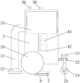
FIG. 1 is a schematic structural view of the present invention;
FIG. 2 is a schematic cross-sectional view of a standpipe and transfer line connection of the present invention;
FIG. 3 is a schematic right-view of the structure of the present invention;
FIG. 4 is a schematic front view of the structure of the present invention;
FIG. 5 is a right side view of the attachment of the stationary plate to a second motor in accordance with the present invention;
fig. 6 is a schematic diagram of the system of the present invention.
In the figure: 1 box body, 2 water tank, 3 sealing cover, 4 water pump, 5 vertical pipe, 6 moving pipe, 7 rotary table, 8 water leakage hole, 9 brush hair, 10 bearing sleeve, 11 moving plate, 12 electric telescopic rod, 13 worm wheel, 14 first motor, 15 worm, 16 double-shaft motor, 17 cross bar, 18 first gear, 19 rotating rod, 20 roller, 21 second gear, 22 fixing plate, 23 second motor, 24 roller seat, 25 steering wheel, 26 funnel cover, 27 fan, 28 short pipe, 29 filter cover, 30 air outlet pipe, 31 dust suction pipe, 32 dust suction cover, 33 box door, 34 obstacle avoidance sensor, 35 controller, 36 signal transceiver, 37 chute, 38 slide block, 39 sealing cover, 40 water feeding pipe, 41 pipe cover, 42 observation hole, 43 liquid level window.
Detailed Description
The technical solutions in the embodiments of the present invention will be clearly and completely described below with reference to the drawings in the embodiments of the present invention, and it is obvious that the described embodiments are only a part of the embodiments of the present invention, and not all of the embodiments. All other embodiments, which can be derived by a person skilled in the art from the embodiments given herein without making any creative effort, shall fall within the protection scope of the present invention.
In the description of the present invention, it should be noted that the terms "upper", "lower", "inner", "outer", "front", "rear", "both ends", "one end", "the other end", and the like indicate orientations or positional relationships based on the orientations or positional relationships shown in the drawings, and are only for convenience of describing the present invention and simplifying the description, but do not indicate or imply that the referred device or element must have a specific orientation, be configured in a specific orientation, and operate, and thus, should not be construed as limiting the present invention. Furthermore, the terms "first" and "second" are used for descriptive purposes only and are not to be construed as indicating or implying relative importance.
In the description of the present invention, it is to be noted that, unless otherwise explicitly specified or limited, the terms "mounted," "disposed," "connected," and the like are to be construed broadly, such as "connected," which may be fixedly connected, detachably connected, or integrally connected; can be mechanically or electrically connected; they may be connected directly or indirectly through intervening media, or they may be interconnected between two elements. The specific meanings of the above terms in the present invention can be understood in specific cases to those skilled in the art.
The box body 1, the water tank 2, the sealing cover 3, the water pump 4, the vertical pipe 5, the moving pipe 6, the rotating disc 7, the water leakage hole 8, the brush hair 9, the bearing sleeve 10, the moving plate 11, the electric telescopic rod 12, the worm wheel 13, the first motor 14, the worm 15, the double-shaft motor 16, the cross rod 17, the first gear 18, the rotating rod 19, the roller 20, the second gear 21, the fixed plate 22, the second motor 23, the roller seat 24, the steering wheel 25, the funnel cover 26, the fan 27, the short pipe 28, the filter cover 29, the air outlet pipe 30, the dust suction pipe 31, the dust suction cover 32, the box door 33, the obstacle avoidance sensor 34, the controller 35, the signal transceiver 36, the chute 37, the sliding block 38, the sealing sleeve 39, the water feeding pipe 40, the pipe cover 41, the observation hole 42 and the liquid level window 43 of the invention are all parts known, the structure and principle are known to the skilled person through technical manuals or through routine experimentation.
Referring to fig. 1-6, an indoor cleaning robot comprises a box body 1, a water tank 2 is fixedly connected to an inner cavity of the box body 1, a sealing cover 3 is fixedly connected to the bottom of the inner cavity of the water tank 2, a water pump 4 is fixedly connected to the top of the sealing cover 3, a water inlet pipe of the water pump 4 is communicated with the top of the sealing cover 3, a vertical pipe 5 is communicated with the bottom of the water tank 2, a moving pipe 6 is arranged inside the vertical pipe 5, the bottom of the moving pipe 6 penetrates through the bottom of the inner cavity of the box body 1 and extends to the outside of the box body 1, a rotating disc 7 is communicated with the bottom of the moving pipe 6, a water leakage hole 8 is formed in the bottom of the rotating disc 7, brush hairs 9 are fixedly connected to the bottom of the rotating disc 7, a bearing sleeve 10 is sleeved on the surface of the moving pipe 6, the bearing sleeve 10 is movably connected with the, the inner ring of the sealing bearing is fixedly connected with the moving pipe 6, the outer ring of the sealing bearing is fixedly connected with the bearing sleeve 10, the bearing sleeve 10 is arranged and can support the moving pipe 6, the moving pipe 6 is convenient to rotate, sliding grooves 37 are formed in two sides of an inner cavity of the vertical pipe 5, sliding blocks 38 are fixedly connected to the tops of two sides of the moving pipe 6, one side, far away from the moving pipe 6, of each sliding block 38 extends to the inner cavity of each sliding groove 37, each sliding block 38 is in sliding connection with each sliding groove 37, a sealing sleeve 39 is arranged at the joint of the vertical pipe 5 and the moving pipe 6, each sealing sleeve 39 is sleeved on the surface of the moving pipe 6, each sealing sleeve 39 is fixedly connected with the vertical pipe 5, the moving pipe 6 can be supported in a balanced mode through the sliding grooves 37 and the sliding blocks 38, the vertical moving pipe 6 is convenient to move, the sealing sleeve 39 is arranged, the sealing performance between, a moving plate 11 is fixedly connected to one side opposite to the bearing sleeve 10, an electric telescopic rod 12 is fixedly connected to the top of the moving plate 11, the bottom of the electric telescopic rod 12 penetrates through an inner cavity of the box body 1 and is fixedly connected with the box body 1, a worm wheel 13 is fixedly sleeved on the surface of the vertical pipe 5, a first motor 14 is fixedly connected to the right side of the bottom of the box body 1, a worm 15 is fixedly connected to the left end of a rotating shaft of the first motor 14, the left end of the worm 15 is movably connected with the left side of the inner cavity of the box body 1, the worm 15 is meshed with the back surface of the worm wheel 13, a double-shaft motor 16 is fixedly connected to the bottom of the water tank 2 through a bracket, a cross rod 17 is fixedly connected to the rotating shaft of the double-shaft motor 16, one end of the cross rod 17, far away from the rotating shaft, a roller 20 is fixedly connected to one end of the rotating rod 19 far away from the box body 1, a second gear 21 is sleeved on the surface of the rotating rod 19, the first gear 18 is meshed with the second gear 21, a first tooth is fixedly connected to the surface of the first gear 18, a second tooth matched with the first tooth is fixedly connected to the surface of the second gear 21, the second gear 21 is fixedly connected with the rotating rod 19, a fixing plate 22 is fixedly connected to the bottom of the inner cavity of the box body 1, a second motor 23 is fixedly connected to the top of the fixing plate 22, the bottom of the rotating shaft of the second motor 23 penetrates through the fixing plate 22 and is fixedly connected with a roller seat 24, a steering wheel 25 is movably connected to the bottom of the roller seat 24 through the rotating shaft, the fixing plate 22, the second motor 23, the roller seat 24 and the steering wheel 25 are arranged to support the box body 1 and facilitate steering when the robot moves, a funnel cover 26 is fixedly connected to the top, the inner cavity of the funnel cover 26 is fixedly connected with a fan 27 through a bracket, the fan 27 can be protected by arranging a filter cover 29, dust in the inner cavity of the box body 1 can be prevented from entering the inner cavity of the funnel cover 26 to corrode the fan 27, the bottom of the funnel cover 26 is communicated with a short pipe 28, the bottom of the short pipe 28 is sleeved with the filter cover 29, the top of the box body 1 is communicated with an air outlet pipe 30, the air outlet pipe 30 is arranged to facilitate air exhaust at the top of the inner cavity of the box body 1 and facilitate air flow circulation, the front of the box body 1 is communicated with a dust suction pipe 31, one end of the dust suction pipe 31, which is far away from the box body 1, is communicated with a dust suction cover 32, the top at the right side of the box body 1 is movably connected with a box door 33 through a hinge, the box door 33 is arranged to facilitate cleaning of the dust in the inner, the left side of the top of the box body 1 is fixedly connected with a signal transceiver 36, the signal transceiver 36 is electrically connected with a controller 35 in a bidirectional mode, the output end of an obstacle avoidance sensor 34 is electrically connected with the input end of the controller 35, the controller 35 is respectively electrically connected with the first motor 14, the second motor 23, the double-shaft motor 16, the electric telescopic rod 12 and the fan 27, through the arrangement of the signal transceiver 36, the wireless remote control of the robot is realized by receiving an instruction sent from the outside, the top of the right side of the water tank 2 is communicated with a water adding pipe 40, one end, far away from the water tank 2, of the water adding pipe 40 penetrates through the box body 1 and extends to the outside of the box body 1, the top of the water adding pipe 40 is sleeved with a pipe cover 41, the water adding pipe 40 is in threaded connection with the pipe cover 41, the bottom of the right side of the box body 1 is provided with an observation, the water level of the water in the water tank 2 can be conveniently observed by arranging the observation hole 42 and the liquid level window 43, the water level of the water in the water tank 2 can be conveniently observed by matching the box body 1, the water tank 2, the sealing cover 3, the water pump 4, the vertical pipe 5, the moving pipe 6, the rotary table 7, the water leakage hole 8, the brush hair 9, the bearing sleeve 10, the moving plate 11, the electric telescopic rod 12, the worm wheel 13, the first motor 14, the worm 15, the double-shaft motor 16, the cross rod 17, the first gear 18, the rotary rod 19, the roller 20, the second gear 21, the fixed plate 22, the second motor 23, the roller seat 24, the steering wheel 25, the funnel cover 26, the fan 27, the short pipe 28, the filter cover 29, the air outlet pipe 30, the dust suction pipe 31 and the dust suction cover 32, the floor cleaning, washing and dust suction are achieved, the cleaning effect is good, the movement flexibility is high, the problems that the existing indoor cleaning robot, the floor can not be cleaned and washed, so that the floor is not clean, the flexibility of movement is poor, and the applicability of the cleaning robot is reduced.
An indoor cleaning robot and a working principle thereof comprise the following steps:
a: the pipe cover 41 is opened, water is added into the inner cavity of the water tank 2 through the water adding pipe 40, the controller 35 controls the fan 27 to operate, the airflow in the inner cavity of the funnel cover 26 flows upwards, the dust on the ground is sucked into the inner cavity of the dust suction pipe 31 through the dust suction cover 32, and the dust enters the inner cavity of the box body 1 through the dust suction pipe 31;
b: the controller 35 controls the electric telescopic rod 12 to extend to drive the movable plate 11 to move downwards, the movable plate 11 drives the bearing sleeve 10 to move downwards, the bearing sleeve 10 drives the movable pipe 6 to move downwards, the movable pipe 6 drives the rotary table 7 and the bristles 9 to move downwards by a certain amount, so that the bristles 9 are contacted with the ground, the controller 35 controls the rotating shaft of the first motor 14 to drive the worm 15 to rotate, the worm 15 drives the worm wheel 13 to rotate, the worm wheel 13 drives the vertical pipe 5 to rotate, the vertical pipe 5 drives the sliding block 38 to rotate through the sliding groove 37, the sliding block 38 drives the movable pipe 6 to rotate, and the movable pipe 6 drives the rotary table 7 and the bristles 9 to rotate so as to;
c: the controller 35 controls the water pump 4 to operate, water in the inner cavity of the water tank 2 is conveyed into the inner cavity of the sealing cover 3, so that the pressure in the inner cavity of the sealing cover 3 is increased, the water in the inner cavity of the sealing cover 3 sequentially enters the inner cavity of the rotary table 7 through the vertical pipe 5 and the moving pipe 6, the water in the inner cavity of the rotary table 7 flows to the ground through the water leakage hole 8, the ground is wet, and the ground can be better washed;
d: the controller 35 controls the rotating shaft of the double-shaft motor 16 to drive the cross rod 17 to rotate, the cross rod 17 drives the first gear 18 to rotate, the first gear 18 drives the second gear 21 to rotate, the second gear 21 drives the rotating rod 19 to rotate, and the rotating rod 19 drives the roller 20 to rotate, so that the cleaning robot moves, and positions where the ground is not used are cleaned;
e: when the cleaning robot encounters an obstacle in the moving process, the obstacle avoidance sensor 34 detects that the obstacle is in front of the dust collection pipe 31, information is fed back to the controller 35, the controller 35 controls the rotating shaft of the second motor 23 to drive the roller seat 24 to rotate, and the roller seat 24 drives the steering wheel 25 to rotate, so that the mobile robot turns to avoid the obstacle.
In summary, the following steps: the indoor cleaning robot and the working principle solve the problems that the existing indoor cleaning robot has single function, mostly only has single dust collection function and can not clean and wash the ground by matching a box body 1, a water tank 2, a sealing cover 3, a water pump 4, a vertical pipe 5, a moving pipe 6, a rotating disc 7, a water leakage hole 8, bristles 9, a bearing sleeve 10, a moving plate 11, an electric telescopic rod 12, a worm wheel 13, a first motor 14, a worm 15, a double-shaft motor 16, a cross bar 17, a first gear 18, a rotating rod 19, a roller 20, a second gear 21, a fixed plate 22, a second motor 23, a roller seat 24, a steering wheel 25, a funnel cover 26, a fan 27, a short pipe 28, a filter cover 29, an air outlet pipe 30, a dust collection pipe 31 and a dust collection cover 32, the floor is not clean, the moving flexibility is poor, and the applicability of the cleaning robot is reduced.
Although embodiments of the present invention have been shown and described, it will be appreciated by those skilled in the art that changes, modifications, substitutions and alterations can be made in these embodiments without departing from the principles and spirit of the invention, the scope of which is defined in the appended claims and their equivalents.
Claims (8)
1. The utility model provides an indoor cleaning machines people, includes box (1), its characterized in that: the water pump type water tank is characterized in that a water tank (2) is fixedly connected to the inner cavity of the tank body (1), a sealing cover (3) is fixedly connected to the bottom of the inner cavity of the water tank (2), a water pump (4) is fixedly connected to the top of the sealing cover (3), a water inlet pipe of the water pump (4) is communicated with the top of the sealing cover (3), a vertical pipe (5) is communicated with the bottom of the water tank (2), a moving pipe (6) is arranged inside the vertical pipe (5), the bottom of the moving pipe (6) penetrates through the bottom of the inner cavity of the tank body (1) and extends to the outside of the tank body (1), a turntable (7) is communicated with the bottom of the turntable (7), a water leakage hole (8) is formed in the bottom of the turntable (7), brush bristles (9) are fixedly connected to the bottom of the turntable (7), a bearing sleeve (10) is sleeved on the surface of the moving pipe (6), the utility model discloses a bearing bush is characterized by comprising a bearing bush (10), a movable plate (11) fixedly connected with one side opposite to the bearing bush (10), an electric telescopic rod (12) fixedly connected with the top of the movable plate (11), the bottom of the electric telescopic rod (12) runs through to the inner chamber of the box (1) and fixedly connected with the box (1), a worm wheel (13) is sleeved on the surface of the vertical pipe (5), a first motor (14) is fixedly connected with the right side of the bottom of the box (1), a worm (15) is fixedly connected with the left end of the rotating shaft of the first motor (14), the left end of the worm (15) is movably connected with the left side of the inner chamber of the box (1), the worm (15) is meshed with the back of the worm wheel (13), a double-shaft motor (16) is fixedly connected with the bottom of the water tank (2) through a bracket, a transverse rod (17) is fixedly connected with the rotating shaft of the double-shaft motor, the automatic hopper-opening device is characterized in that the cross rod (17) is located at one end outside the box body (1) and is fixedly connected with a first gear (18), rotating rods (19) are movably connected to the bottoms of two sides of the box body (1), one end of each rotating rod (19) far away from the box body (1) is fixedly connected with a roller (20), a second gear (21) is sleeved on the surface of each rotating rod (19), the first gear (18) is meshed with the second gear (21), a fixing plate (22) is fixedly connected to the bottom of an inner cavity of the box body (1), a second motor (23) is fixedly connected to the top of the fixing plate (22), the bottom of a rotating shaft of the second motor (23) penetrates through the fixing plate (22) and is fixedly connected with a roller seat (24), the bottom of the roller seat (24) is movably connected with a steering wheel (25) through the rotating shaft, and a hopper cover (, the inner cavity of the funnel cover (26) is fixedly connected with a fan (27) through a support, the bottom of the funnel cover (26) is communicated with a short pipe (28), the bottom of the short pipe (28) is sleeved with a filter cover (29), the top of the box body (1) is communicated with an air outlet pipe (30), the front of the box body (1) is communicated with a dust suction pipe (31), one end, far away from the box body (1), of the dust suction pipe (31) is communicated with a dust suction cover (32), the top of the right side of the box body (1) is movably connected with a box door (33) through a hinge, the front of the dust suction pipe (31) is fixedly connected with an obstacle avoidance sensor (34), the front top of the box body (1) is fixedly connected with a controller (35), the left side of the top of the box body (1) is fixedly connected with a signal transceiver (36), and the signal transceiver (, the output end of the obstacle avoidance sensor (34) is electrically connected with the input end of a controller (35), and the controller (35) is electrically connected with the first motor (14), the second motor (23), the double-shaft motor (16), the electric telescopic rod (12) and the fan (27) respectively.
2. An indoor cleaning robot as claimed in claim 1, wherein: a sealing bearing is arranged between the bearing sleeve (10) and the moving pipe (6), the sealing bearing is sleeved on the surface of the moving pipe (6), an inner ring of the sealing bearing is fixedly connected with the moving pipe (6), and an outer ring of the sealing bearing is fixedly connected with the bearing sleeve (10).
3. An indoor cleaning robot as claimed in claim 1, wherein: spout (37) have all been seted up to the both sides of standpipe (5) inner chamber, the equal fixedly connected with slider (38) in top of removal pipe (6) both sides, one side that removal pipe (6) were kept away from in slider (38) extends to the inner chamber of spout (37), slider (38) and spout (37) sliding connection.
4. An indoor cleaning robot as claimed in claim 1, wherein: a sealing sleeve (39) is arranged at the joint of the vertical pipe (5) and the movable pipe (6), the sealing sleeve (39) is sleeved on the surface of the movable pipe (6), and the sealing sleeve (39) is fixedly connected with the vertical pipe (5).
5. An indoor cleaning robot as claimed in claim 1, wherein: the surface of the first gear (18) is fixedly connected with first teeth, the surface of the second gear (21) is fixedly connected with second teeth matched with the first teeth, and the second gear (21) is fixedly connected with the rotating rod (19).
6. An indoor cleaning robot as claimed in claim 1, wherein: the top intercommunication on water tank (2) right side has filler pipe (40), the one end that water tank (2) were kept away from in filler pipe (40) runs through box (1) and extends to the outside of box (1), the top cover of filler pipe (40) is equipped with tube cap (41), filler pipe (40) and tube cap (41) threaded connection.
7. An indoor cleaning robot as claimed in claim 1, wherein: observation hole (42) have been seted up to the bottom on box (1) right side, the right side fixedly connected with liquid level window (43) of water tank (2), the surface spraying of liquid level window (43) has the scale mark.
8. An indoor cleaning robot and working principle according to claims 1-8, characterized by comprising the following steps:
a: the pipe cover (41) is opened, water source is added into the inner cavity of the water tank (2) through the water adding pipe (40), the controller (35) controls the fan (27) to operate, air flow in the inner cavity of the funnel cover (26) flows upwards, dust on the ground is sucked into the inner cavity of the dust suction pipe (31) through the dust suction cover (32), and enters the inner cavity of the box body (1) through the dust suction pipe (31);
b: the controller (35) controls the electric telescopic rod (12) to extend to drive the movable plate (11) to move downwards, the movable plate (11) drives the bearing sleeve (10) to move downwards, the bearing sleeve (10) drives the movable pipe (6) to move downwards, the movable pipe (6) drives the rotary table (7) and the bristles (9) to move downwards by a certain amount, so that the bristles (9) are in contact with the ground, the controller (35) controls a rotating shaft of the first motor (14) to drive the worm (15) to rotate, the worm (15) drives the worm wheel (13) to rotate, the worm wheel (13) drives the vertical pipe (5) to rotate, the vertical pipe (5) drives the sliding block (38) to rotate through the sliding groove (37), the sliding block (38) drives the movable pipe (6) to rotate, and the movable pipe (6) drives the rotary table (7) and the bristles (9) to;
c: the controller (35) controls the water pump (4) to operate, water in the inner cavity of the water tank (2) is conveyed into the inner cavity of the sealing cover (3), so that the pressure of the inner cavity of the sealing cover (3) is increased, the water in the inner cavity of the sealing cover (3) sequentially enters the inner cavity of the turntable (7) through the vertical pipe (5) and the moving pipe (6), and the water in the inner cavity of the turntable (7) flows to the ground through the water leakage holes (8), so that the ground is wet, and the ground can be better washed;
d: the controller (35) controls a rotating shaft of the double-shaft motor (16) to drive the cross rod (17) to rotate, the cross rod (17) drives the first gear (18) to rotate, the first gear (18) drives the second gear (21) to rotate, the second gear (21) drives the rotating rod (19) to rotate, and the rotating rod (19) drives the roller (20) to rotate, so that the cleaning robot moves to clean the positions, which are not used on the ground;
e: when the cleaning robot encounters an obstacle in the moving process, the obstacle avoidance sensor (34) detects that the obstacle is in front of the dust collection pipe (31), information is fed back to the controller (35), the controller (35) controls a rotating shaft of the second motor (23) to drive the roller seat (24) to rotate, the roller seat (24) drives the steering wheel (25) to rotate, and the moving robot is made to turn to avoid the obstacle.
Priority Applications (1)
| Application Number | Priority Date | Filing Date | Title |
|---|---|---|---|
| CN201910800925.7A CN110754999B (en) | 2019-08-28 | 2019-08-28 | Indoor cleaning robot and working principle |
Applications Claiming Priority (1)
| Application Number | Priority Date | Filing Date | Title |
|---|---|---|---|
| CN201910800925.7A CN110754999B (en) | 2019-08-28 | 2019-08-28 | Indoor cleaning robot and working principle |
Publications (2)
| Publication Number | Publication Date |
|---|---|
| CN110754999A true CN110754999A (en) | 2020-02-07 |
| CN110754999B CN110754999B (en) | 2021-03-02 |
Family
ID=69329490
Family Applications (1)
| Application Number | Title | Priority Date | Filing Date |
|---|---|---|---|
| CN201910800925.7A Active CN110754999B (en) | 2019-08-28 | 2019-08-28 | Indoor cleaning robot and working principle |
Country Status (1)
| Country | Link |
|---|---|
| CN (1) | CN110754999B (en) |
Cited By (6)
| Publication number | Priority date | Publication date | Assignee | Title |
|---|---|---|---|---|
| CN111297270A (en) * | 2020-03-31 | 2020-06-19 | 西安工程大学 | Sweeping device of sweeping robot |
| CN111498328A (en) * | 2020-04-15 | 2020-08-07 | 陈吉梅 | Environment-friendly classified recycling garbage can and using method |
| CN112171681A (en) * | 2020-08-27 | 2021-01-05 | 南京驭逡通信科技有限公司 | Multidirectional moving mechanism for welcome robot |
| CN112212121A (en) * | 2020-09-16 | 2021-01-12 | 南京驭逡通信科技有限公司 | Municipal administration underground piping inspection robot |
| CN112741563A (en) * | 2021-01-04 | 2021-05-04 | 成都职业技术学院 | Indoor ground wall cleaning device |
| CN112806907A (en) * | 2021-01-07 | 2021-05-18 | 浙江广厦建设职业技术大学 | Intelligence house clearance is with robot of sweeping floor |
Citations (15)
| Publication number | Priority date | Publication date | Assignee | Title |
|---|---|---|---|---|
| CN1144642A (en) * | 1995-09-07 | 1997-03-12 | 黄平 | Multipurpose cleaning machine |
| JP2003325406A (en) * | 2002-05-17 | 2003-11-18 | Toshiba Tec Corp | Self-propelled cleaner |
| KR20040086643A (en) * | 2003-04-03 | 2004-10-12 | 주식회사 한울로보틱스 | suction equipment of vacuum cleaning robot worked by motor |
| US20060010640A1 (en) * | 2004-07-16 | 2006-01-19 | Yasuhiro Oka | Vacuum cleaner |
| CN1767781A (en) * | 2003-02-21 | 2006-05-03 | 坦南特公司 | Dual mode carpet cleaning apparatus utilizing an extraction device and a soil transfer cleaning medium |
| CN201388979Y (en) * | 2009-03-28 | 2010-01-27 | 李新民 | High-rise building cleaning device |
| CN204636228U (en) * | 2015-05-27 | 2015-09-16 | 遂宁市长丰机械科技有限公司 | A kind of Multipurpose broom |
| CN205963938U (en) * | 2016-07-01 | 2017-02-22 | 荆门市吉光环保科技有限责任公司 | Take deposition cleaning device's dust catcher |
| CN206063082U (en) * | 2016-07-23 | 2017-04-05 | 皮武 | Dust collecting and floor mopping dehydrator |
| CN108143355A (en) * | 2017-12-25 | 2018-06-12 | 郑州游爱网络技术有限公司 | A kind of household floor tile high-efficiency cleaning device |
| CN108774979A (en) * | 2018-07-09 | 2018-11-09 | 南京海晨霞工程科技有限公司 | A kind of bridge construction guard bar washing device easy to remove |
| CN108992002A (en) * | 2018-06-28 | 2018-12-14 | 芜湖泰领信息科技有限公司 | Intelligent sweeping machine |
| CN208301598U (en) * | 2018-01-04 | 2019-01-01 | 江苏英凯电机有限公司 | A kind of electric sweeper |
| CN109199261A (en) * | 2017-06-30 | 2019-01-15 | 沈阳新松机器人自动化股份有限公司 | Scrubbing brush dish structure is washed in pressure automatic adjustment |
| CN109199247A (en) * | 2018-10-17 | 2019-01-15 | 王亮 | A kind of economizing clean robot |
-
2019
- 2019-08-28 CN CN201910800925.7A patent/CN110754999B/en active Active
Patent Citations (15)
| Publication number | Priority date | Publication date | Assignee | Title |
|---|---|---|---|---|
| CN1144642A (en) * | 1995-09-07 | 1997-03-12 | 黄平 | Multipurpose cleaning machine |
| JP2003325406A (en) * | 2002-05-17 | 2003-11-18 | Toshiba Tec Corp | Self-propelled cleaner |
| CN1767781A (en) * | 2003-02-21 | 2006-05-03 | 坦南特公司 | Dual mode carpet cleaning apparatus utilizing an extraction device and a soil transfer cleaning medium |
| KR20040086643A (en) * | 2003-04-03 | 2004-10-12 | 주식회사 한울로보틱스 | suction equipment of vacuum cleaning robot worked by motor |
| US20060010640A1 (en) * | 2004-07-16 | 2006-01-19 | Yasuhiro Oka | Vacuum cleaner |
| CN201388979Y (en) * | 2009-03-28 | 2010-01-27 | 李新民 | High-rise building cleaning device |
| CN204636228U (en) * | 2015-05-27 | 2015-09-16 | 遂宁市长丰机械科技有限公司 | A kind of Multipurpose broom |
| CN205963938U (en) * | 2016-07-01 | 2017-02-22 | 荆门市吉光环保科技有限责任公司 | Take deposition cleaning device's dust catcher |
| CN206063082U (en) * | 2016-07-23 | 2017-04-05 | 皮武 | Dust collecting and floor mopping dehydrator |
| CN109199261A (en) * | 2017-06-30 | 2019-01-15 | 沈阳新松机器人自动化股份有限公司 | Scrubbing brush dish structure is washed in pressure automatic adjustment |
| CN108143355A (en) * | 2017-12-25 | 2018-06-12 | 郑州游爱网络技术有限公司 | A kind of household floor tile high-efficiency cleaning device |
| CN208301598U (en) * | 2018-01-04 | 2019-01-01 | 江苏英凯电机有限公司 | A kind of electric sweeper |
| CN108992002A (en) * | 2018-06-28 | 2018-12-14 | 芜湖泰领信息科技有限公司 | Intelligent sweeping machine |
| CN108774979A (en) * | 2018-07-09 | 2018-11-09 | 南京海晨霞工程科技有限公司 | A kind of bridge construction guard bar washing device easy to remove |
| CN109199247A (en) * | 2018-10-17 | 2019-01-15 | 王亮 | A kind of economizing clean robot |
Cited By (8)
| Publication number | Priority date | Publication date | Assignee | Title |
|---|---|---|---|---|
| CN111297270A (en) * | 2020-03-31 | 2020-06-19 | 西安工程大学 | Sweeping device of sweeping robot |
| CN111297270B (en) * | 2020-03-31 | 2021-07-13 | 西安工程大学 | Sweeping device of sweeping robot |
| CN111498328A (en) * | 2020-04-15 | 2020-08-07 | 陈吉梅 | Environment-friendly classified recycling garbage can and using method |
| CN112171681A (en) * | 2020-08-27 | 2021-01-05 | 南京驭逡通信科技有限公司 | Multidirectional moving mechanism for welcome robot |
| CN112212121A (en) * | 2020-09-16 | 2021-01-12 | 南京驭逡通信科技有限公司 | Municipal administration underground piping inspection robot |
| CN112741563A (en) * | 2021-01-04 | 2021-05-04 | 成都职业技术学院 | Indoor ground wall cleaning device |
| CN112806907A (en) * | 2021-01-07 | 2021-05-18 | 浙江广厦建设职业技术大学 | Intelligence house clearance is with robot of sweeping floor |
| CN112806907B (en) * | 2021-01-07 | 2022-03-04 | 浙江广厦建设职业技术大学 | Intelligence house clearance is with robot of sweeping floor |
Also Published As
| Publication number | Publication date |
|---|---|
| CN110754999B (en) | 2021-03-02 |
Similar Documents
| Publication | Publication Date | Title |
|---|---|---|
| CN110754999B (en) | Indoor cleaning robot and working principle | |
| CN108670129B (en) | Intelligent floor sweeping robot based on Internet of things and implementation method thereof | |
| CN108372508A (en) | A kind of intelligence Sao Xituo robots | |
| CN111329389B (en) | Dust absorption detachable type robot of sweeping floor | |
| CN107080500B (en) | Intelligent cleaning robot system | |
| CN108497984B (en) | Toilet lid with cleaning and disinfecting functions | |
| CN209018628U (en) | A kind of use for laboratory floor-mopping robot | |
| CN108606736A (en) | A kind of use for laboratory floor-mopping robot | |
| CN204097741U (en) | Collar, coat-sleeve wash mill and washing machine | |
| CN211299811U (en) | Cleaning and floor sweeping robot device | |
| CN108685530A (en) | A kind of interior automatic adjustment Intelligent cleaning robot | |
| CN104889095A (en) | Multifunctional cleaning mechanism, cleaning technology and modular combined type cleaning working station | |
| CN203000795U (en) | Vacuum sweeper capable of spanning inside corner to work and cleaning vertical plane surfaces and ceiling surfaces | |
| CN204974546U (en) | Multi -functional wiper mechanism and modularization combination formula cleaning station | |
| CN207959405U (en) | A kind of Full-automatic toilet bowl cleaning equipment | |
| CN109077677A (en) | A kind of energy-saving duster of rollable | |
| CN111297270A (en) | Sweeping device of sweeping robot | |
| CN105708390A (en) | Cleaner with self-cleaning type structure | |
| CN110419986A (en) | A kind of automatic sweeping machine device people | |
| CN213033117U (en) | Material spraying and cleaning equipment for industrial processing | |
| CN213887279U (en) | Hand-push type die table sweeper | |
| CN205393088U (en) | Impeller rotation type ultrasonic cleaner | |
| CN205758450U (en) | Cleaner with self-cleaning type structure | |
| CN211639398U (en) | Angle grinder for electric power construction | |
| CN203914789U (en) | A kind of Novel clean machine |
Legal Events
| Date | Code | Title | Description |
|---|---|---|---|
| PB01 | Publication | ||
| PB01 | Publication | ||
| SE01 | Entry into force of request for substantive examination | ||
| SE01 | Entry into force of request for substantive examination | ||
| GR01 | Patent grant | ||
| GR01 | Patent grant |