CN110683363A - Lifting system is piled up to box - Google Patents
Lifting system is piled up to box Download PDFInfo
- Publication number
- CN110683363A CN110683363A CN201910836254.XA CN201910836254A CN110683363A CN 110683363 A CN110683363 A CN 110683363A CN 201910836254 A CN201910836254 A CN 201910836254A CN 110683363 A CN110683363 A CN 110683363A
- Authority
- CN
- China
- Prior art keywords
- lifting
- box
- box body
- rack
- motor
- Prior art date
- Legal status (The legal status is an assumption and is not a legal conclusion. Google has not performed a legal analysis and makes no representation as to the accuracy of the status listed.)
- Pending
Links
Images


Classifications
-
- B—PERFORMING OPERATIONS; TRANSPORTING
- B65—CONVEYING; PACKING; STORING; HANDLING THIN OR FILAMENTARY MATERIAL
- B65G—TRANSPORT OR STORAGE DEVICES, e.g. CONVEYORS FOR LOADING OR TIPPING, SHOP CONVEYOR SYSTEMS OR PNEUMATIC TUBE CONVEYORS
- B65G57/00—Stacking of articles
- B65G57/30—Stacking of articles by adding to the bottom of the stack
- B65G57/301—Stacking of articles by adding to the bottom of the stack by means of reciprocatory or oscillatory lifting and holding or gripping devices
- B65G57/303—Stacking of articles by adding to the bottom of the stack by means of reciprocatory or oscillatory lifting and holding or gripping devices the stack being lowered by mobile grippers or holders onto added articles
-
- B—PERFORMING OPERATIONS; TRANSPORTING
- B65—CONVEYING; PACKING; STORING; HANDLING THIN OR FILAMENTARY MATERIAL
- B65G—TRANSPORT OR STORAGE DEVICES, e.g. CONVEYORS FOR LOADING OR TIPPING, SHOP CONVEYOR SYSTEMS OR PNEUMATIC TUBE CONVEYORS
- B65G2201/00—Indexing codes relating to handling devices, e.g. conveyors, characterised by the type of product or load being conveyed or handled
- B65G2201/02—Articles
- B65G2201/0235—Containers
- B65G2201/0258—Trays, totes or bins
Abstract
The invention relates to the technical field of transported articles, in particular to a box stacking and lifting system which comprises a rack, wherein a lifting reciprocating device, a transporting device and a guiding device are arranged on the rack, the guiding device comprises a plurality of guiding rods which are arranged on the rack and used for limiting the box to vertically slide, the lifting reciprocating device comprises a plurality of lifting plates, and the lifting plates are vertically and slidably connected to the rack; after the lifting reciprocating device lifts first box, the conveyer transports second box under to first box, and the lifting reciprocating device descends and makes two box laminating, and reciprocating device rises again with two box lifting simultaneously, and after a plurality of box lifting pile, the box group that a plurality of boxes formed. According to the invention, the mechanism for fixing the box body, which is arranged at a certain height, is removed, the structure is simplified, the existing stacking and lifting mode is changed, and the existing mode of sequentially lifting and stacking the box body is optimized to be a mode of stacking from bottom to top, so that the production cost is reduced, and the box body stacking device is more worthy of popularization.
Description
Technical Field
The invention relates to the technical field of transported goods, in particular to a box body stacking and lifting system.
Background
At present, generally, the goods are installed in the box body and transported through the transport box body.
When the current transport of freight or storage, because the demand of space or efficiency, often need with box pile together back storage or transportation, the mode of piling up of current small-size packing box all adopts the manual work to stack, and efficiency is extremely low, especially to the transportation trade, can't in time pile up the goods fast and greatly influence its work efficiency, and simultaneously, artifical intensity of labour is very big, wastes time and energy.
To the above-mentioned problem, application number is CN 201620066058.0's utility model discloses a box lifting system for box stacks, which comprises a motor, drive chain, the gear, lifter plate and the guide bar along vertical setting, two lifter plates are just to setting up, the inboard of two lifter plates all is provided with the box supporting part that is located same level department, every lifter plate all corresponds and is provided with the guide bar, the lifter plate slides and sets up on the guide bar that corresponds, every lifter plate all corresponds and is provided with along vertical driven drive chain, and the lifter plate is rather than the drive chain fixed connection that corresponds, drive chain's upper and lower both ends are equallyd divide and are do not correspond and be provided with the gear, one of them gear that every drive chain corresponds is by motor drive. The box lifting system can automatically and rapidly lift and descend the box, a mechanism for fixing the box is arranged above the box lifting system correspondingly, the box can be lifted and stacked in sequence, and the stacked box is conveyed away after being lowered in a unified mode. Need carry out the stack when transporting or saving with solving present box, otherwise very occupation space, and present mode efficiency of piling up is low excessively, still needs the manual work to pile up small-size packing box, intensity of labour too big scheduling problem.
The lifting mode needs to arrange the fixed box mechanism at a certain height of the system, and the mechanism for arranging the fixed box at a certain height is troublesome, so that the structure is complex, and finally the cost of the device is high.
Disclosure of Invention
The invention mainly aims to provide a box body stacking and lifting system, which solves the technical problem that in the prior art, the structure is complex, and the cost of the device is overhigh finally, and achieves the purpose.
The technical scheme adopted by the invention is as follows: the box stacking and lifting system comprises a rack, wherein a lifting reciprocating device, a conveying device and a guiding device are arranged on the rack, the guiding device comprises a plurality of guide rods which are arranged on the rack and used for limiting the vertical sliding of a box body, the lifting reciprocating device comprises a plurality of groups of lifting plates which are connected to the rack in a sliding manner, clamping devices are arranged on the inner sides of the lifting plates, the clamping devices are connected with clamping plates used for clamping articles, a connecting plate is fixedly connected between each group of lifting plates, and a transmission mechanism which drives the lifting plates vertically is correspondingly arranged on the connecting plate; work as after the lifting reciprocating device lifts first box, the conveyer transports second box under to first box, the lifting reciprocating device descends and makes two box laminating, and reciprocating device rises once more and lifts two boxes simultaneously, and is a plurality of after the box lifting is piled up, it is a plurality of the box group that the box formed to transport through the conveyer.
Further optimize, drive mechanism is including installing the first motor in the frame and installing the lifting block on the connecting plate, the first motor be equipped with three output shaft, one of them output shaft coaxial coupling has first gear, lifting block side still is equipped with the belt, partly of belt centers on first gear setting.
Further optimize, drive mechanism is including installing the first motor in the frame and installing the lifting block on the connecting plate, the output shaft of first motor is connected with the sprocket, the sprocket set up in the lifting block.
Further optimize, the conveyer is including installing two slide rails in the frame and installing the second motor in the frame, install the belt on the slide rail, the output shaft coaxial coupling of second motor has two drive wheels, the drive wheel is located the one end of slide rail, the second belt pulley is installed to the other end of slide rail, be connected through the belt on the slide rail between drive wheel and the second belt pulley. The second motor is used for driving the driving wheel to rotate, and the driving wheel is connected with the second belt pulley, so that the belt on the sliding rail is driven to move, and the box body on the sliding rail is driven to move.
Preferably, a support lifting device is connected between the two slide rails and comprises a rotating shaft and a first hydraulic cylinder, the tail end of the first hydraulic cylinder is abutted to the support lifting plate, and two rotating rods are connected between the rotating shaft and the support lifting plate. The lifting plate is convenient for supporting the stacked box body group, so that the box body group can move on the slide rail in a balanced manner, and the stability of the box body group is ensured.
Further optimize, the conveyer still includes two entry limiting plates, two entry limiting plate inboard all is equipped with the second pneumatic cylinder that is used for driving entry limiting plate lateral sliding.
Further optimization, a telescopic rod is connected between the guide rod and the rack; the guide rods are 2 pairs, the telescopic rods between one pair of guide rods and the rack stretch along the advancing direction of the box body and adapt to the length of the box body, and the telescopic rods between the other pair of guide rods and the rack stretch perpendicular to the advancing direction of the box body and adapt to the width of the box body.
Further preferably, the tail end of the conveying device is also provided with a conveying platform for conveying away the stacked box body group.
Preferably, the clamping device comprises a third hydraulic cylinder for adjusting the clamping force of each group of clamping plates, and the third hydraulic cylinder is installed on one side, close to the lifting plate, of each clamping plate.
Since the clamping force of the clamping plates to the cases increases as the number of cases increases.
For convenience of description, the transport direction of the transport device is set as the length direction of the box body, and the transport direction perpendicular to the transport device is set as the width direction of the box body.
The principle of the invention is as follows: the lifter plate explains for a set of as preferred, at first adjust two entry limiting plates, start the second pneumatic cylinder and make two entry limiting plates slide along perpendicular to conveyer direction of transportation, thereby make the width that the distance between two entry limiting plates can adapt to the box, then start the third pneumatic cylinder and make two lifter plates slide along perpendicular to conveyer direction of transportation, thereby make the pinch-off blades can press from both sides tight box, adjust the telescopic link between guide bar and the frame at last, make the box rise the back, four lateral walls of box just laminate with four guide bar inner walls mutually.
Then the box body to be stacked is placed between the two inlet limiting plates and on the two slide rails, a second motor is started, the second motor drives a driving wheel to rotate, the driving wheel drives a second belt wheel to rotate through the action of a belt, so that the belt is driven to move, the box body moves on the slide rails, the box body is clamped by the two clamping plates when the box body slides between the two clamping plates, at the moment, the first motor is started, the first motor drives a lifting block body to lift through the matching transmission of the belt and a first gear or the transmission of a chain wheel, the lifting block body lifts to drive a connecting plate, lifting plates and the clamping plates to lift upwards together, the box body between the two lifting plates also lifts along with the lifting block body, after the lifting block body is lifted to a certain height, the first motor rotates reversely to drive the lifting block body to descend, so that the box body between the two clamping plates also descends, and at the same time, the second box, and when the second box body is just below the first box body, the upper surface of the second box body is attached to the lower surface of the first box body, the two clamping plates are slightly loosened or still keep a clamping state, so that the first box body and the second box body are in a stacking state, the steps are repeated to lift the first box body and the second box body, and in the descending process of the first box body and the second box body, the third box body is just below the second box body, and so on, the stacking and lifting of the plurality of box bodies are completed.
After the stacking and lifting of the boxes are completed, the distance between the two clamping plates is adjusted, so that the clamping plates do not clamp the boxes any more, and the boxes are transported away through the conveying platform.
The invention removes the mechanism for fixing the box body arranged at a certain height, simplifies the structure, adopts two guide rods to replace the existing mechanism for fixing the box body, changes the existing stacking and lifting mode, optimizes the box body lifting and stacking in turn into the mode of stacking from bottom to top, reduces the production cost, and is more worthy of popularization.
Drawings
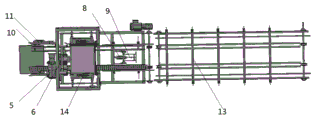
Fig. 1 is a schematic structural diagram of a box stacking and lifting system according to the present invention.
FIG. 2 is a schematic illustration of a front view of the case stack lift system of the present invention.
FIG. 3 is a schematic diagram of a top view of the case stack lift system of the present invention.
FIG. 4 is a schematic diagram of a side view of the case stack lift system of the present invention.
Reference numerals: the device comprises a rack 1, a box body 2, a guide rod 3, a lifting plate 4, a first motor 5, a lifting block 6, an output shaft 7, a first hydraulic cylinder 8, a rotating shaft 9, an inlet limiting plate 10, a second hydraulic cylinder 11, an expansion rod 12, a conveying platform 13, a third hydraulic cylinder 14, a clamping plate 15 and a connecting plate 16.
Detailed Description
The following description is presented to disclose the invention so as to enable any person skilled in the art to practice the invention. The preferred embodiments in the following description are given by way of example only, and other obvious variations will occur to those skilled in the art.
Example 1 of the invention is shown in FIGS. 1-4: the box stacking and lifting system comprises a rack 1, wherein a lifting reciprocating device, a conveying device and a guiding device are arranged on the rack 1, the guiding device comprises a plurality of guide rods 3 which are arranged on the rack 1 and used for limiting a box body 2 to vertically slide, the lifting reciprocating device comprises a group of lifting plates 4 which are vertically and slidably connected onto the rack 1, clamping devices are arranged on the inner sides of the lifting plates 4, the clamping devices are connected with clamping plates 15 used for clamping the box body, the clamping plates 15 in the group of lifting plates 4 are at the same horizontal height, a connecting plate 16 is fixedly connected between the two lifting plates 4, and a transmission mechanism which vertically transmits is correspondingly arranged on the connecting plate 16; work as the reciprocal device of lifting is behind first box 2 lifting, the conveyer transports second box 2 under to first box 2, the reciprocal device of lifting descends and laminates two boxes 2, and the reciprocal device rises once more and lifts two boxes 2 simultaneously, and is a plurality of behind the box 2 lifting pile, it is a plurality of the box group that box 2 formed to transport through the conveyer.
The transmission mechanism comprises a first motor 5 installed on the rack 1 and a lifting block 6 installed on a connecting plate, wherein the first motor 5 is provided with three output shafts 7, one of the output shafts 7 is coaxially connected with a first gear, a belt is further arranged on the side edge of the lifting block 6, and one part of the belt surrounds the first gear.
Drive mechanism is including installing first motor 5 in frame 1 and installing lifting block 6 on the connecting plate, output shaft 7 of first motor 5 is connected with the sprocket, the sprocket set up in the lifting block 6.
The conveyer is including installing two slide rails in frame 1 and installing the second motor in frame 1, install the belt on the slide rail, 7 coaxial coupling of output shaft of second motor have two drive wheels, the drive wheel is located the one end of slide rail, the second belt pulley is installed to the other end of slide rail, be connected through the belt on the slide rail between drive wheel and the second belt pulley.
The lifting device is connected between the two slide rails and comprises a rotating shaft 9 and a first hydraulic cylinder 8, the tail end of the first hydraulic cylinder 8 is abutted to the lifting plate, and two rotating rods are connected between the rotating shaft 9 and the lifting plate.
The conveying device further comprises two inlet limiting plates 10, and second hydraulic cylinders 11 used for driving the inlet limiting plates 10 to transversely slide are arranged on the inner sides of the two inlet limiting plates 10.
A telescopic rod 12 is connected between the guide rod 3 and the frame 1; the guide rods 3 are 2 pairs, the telescopic rods 12 between one pair of guide rods 3 and the rack 1 stretch along the advancing direction of the box body 2 and adapt to the length of the box body 2, and the telescopic rods 12 between the other pair of guide rods 3 and the rack 1 stretch perpendicular to the advancing direction of the box body 2 and adapt to the width of the box body 2. The inner wall of the guide rod 3 is a right-angle side which is matched with the side wall of the box body 2.
The end of the transport device is also provided with a conveying platform 13 for transporting away the stacked box bodies 2.
The clamping device comprises a third hydraulic cylinder 14 for adjusting the clamping force of each group of clamping plates 15, and the third hydraulic cylinder 14 is installed on one side, close to the lifting plate, of each clamping plate 15.
The method comprises the following specific operation steps: at first adjust two entry limiting plates 10, start second pneumatic cylinder 11 and make two entry limiting plates 10 slide along perpendicular to conveyer direction of transportation, thereby make the distance between two entry limiting plates 10 can adapt to the width of box 2, then start third pneumatic cylinder 14 and make two lifter plates 4 slide along perpendicular to conveyer direction of transportation, thereby make two pinch-off blades 15 can press from both sides tight box 2, adjust telescopic link 12 between guide bar 3 and the frame 1 at last, make box 2 rise the back, four lateral walls of box 2 just laminate with 3 inner walls of four guide bars mutually.
Then the box body 2 to be stacked is placed between the two inlet limiting plates 10 and on the two slide rails, the second motor is started, the second motor drives the driving wheel to rotate, the driving wheel drives the second belt pulley to rotate through the action of the belt, so as to drive the belt to move, the box body 2 moves on the slide rails, when the box body 2 slides to a position between the two clamping plates 15, the box body 2 is clamped by the two clamping plates 15, at the moment, the first motor 5 is started, the first motor 5 drives the first belt pulley to rotate, so as to drive the lifting block body 6 to lift, the lifting block body 6 lifts to drive the connecting plate 16, the lifting plate 4 and the clamping plates 15 to lift upwards, the box body 2 between the two clamping plates 15 also lifts, when the lifting block body is lifted to a certain height, the first motor 5 rotates reversely, the lifting block body 6 is driven to descend, so that the box body 2 between the two clamping plates, meanwhile, the second box body 2 is also transported by a belt on a sliding rail, and when the second box body 2 is just below the first box body 2, the upper surface of the second box body 2 is attached to the lower surface of the first box body 2, the two clamping plates 15 are slightly loosened or still keep the original clamping state, so that the first box body 2 and the second box body 2 are in the stacking state, then the steps are repeated to lift the first box body 2 and the second box body 2, the first box body 2 and the second box body 2 are lifted in the descending process, and the third box body 2 is just below the second box body 2, so on, and the stacking and lifting of the plurality of box bodies 2 are completed.
After the stacking and lifting of the plurality of cases 2 are completed, the distance between the two clamping plates 15 is adjusted so that the clamping plates 15 no longer clamp the cases 2, thereby transporting the plurality of cases 2 away through the transport platform 13.
The foregoing shows and describes the general principles, essential features, and advantages of the invention. It will be understood by those skilled in the art that the present invention is not limited to the embodiments described above, which are merely illustrative of the principles of the invention, but that various changes and modifications may be made without departing from the spirit and scope of the invention, which fall within the scope of the invention as claimed. The scope of the invention is defined by the appended claims and equivalents thereof.
Claims (9)
1. Lifting system is piled up to box, including the frame, be equipped with lifting reciprocating device, conveyer and guider in the frame, its characterized in that: the lifting reciprocating device comprises a plurality of groups of lifting plates which are connected to the rack in a sliding manner, clamping devices are arranged on the inner sides of the lifting plates and connected with clamping plates for clamping articles, a connecting plate is fixedly connected between each group of lifting plates, and a transmission mechanism which is vertically driven is correspondingly arranged on the connecting plate; work as after the lifting reciprocating device lifts first box, the conveyer transports second box under to first box, the lifting reciprocating device descends and makes two box laminating, and reciprocating device rises once more and lifts two boxes simultaneously, and is a plurality of after the box lifting is piled up, it is a plurality of the box group that the box formed to transport through the conveyer.
2. The carton stacking and lifting system of claim 1, wherein: the transmission mechanism comprises a first motor and a lifting block, the first motor is installed on the rack, the lifting block is installed on the connecting plate, three output shafts are arranged on the first motor, one of the three output shafts is coaxially connected with a first gear, a belt is further arranged on the side edge of the lifting block, and one part of the belt surrounds the first gear.
3. The carton stacking and lifting system of claim 1, wherein: the transmission mechanism comprises a first motor and a lifting block, the first motor is installed on the rack, the lifting block is installed on the connecting plate, an output shaft of the first motor is connected with a chain wheel, and the chain wheel is arranged in the lifting block.
4. The carton stacking and lifting system of claim 1, wherein: the conveyer is including installing two slide rails in the frame and installing the second motor in the frame, install the belt on the slide rail, the output shaft coaxial coupling of second motor has two drive wheels, the drive wheel is located the one end of slide rail, the second belt pulley is installed to the other end of slide rail, be connected through the belt on the slide rail between drive wheel and the second belt pulley.
5. The carton stacking and lifting system of claim 3, wherein: the lifting device is connected between the two slide rails and comprises a rotating shaft and a first hydraulic cylinder, the tail end of the first hydraulic cylinder is abutted to the lifting plate, and two rotating rods are connected between the rotating shaft and the lifting plate.
6. The carton stacking and lifting system of claim 1, wherein: the conveying device further comprises two inlet limiting plates, and second hydraulic cylinders used for driving the inlet limiting plates to transversely slide are arranged on the inner sides of the two inlet limiting plates.
7. The carton stacking and lifting system of claim 1, wherein: a telescopic rod is connected between the guide rod and the rack; the guide rods are 2 pairs, the telescopic rods between one pair of guide rods and the rack stretch along the advancing direction of the box body and adapt to the length of the box body, and the telescopic rods between the other pair of guide rods and the rack stretch perpendicular to the advancing direction of the box body and adapt to the width of the box body.
8. The carton stacking and lifting system of claim 1, wherein: and the tail end of the conveying device is also provided with a conveying platform for conveying away the stacked box body group.
9. The carton stacking and lifting system of claim 1, wherein: the clamping device comprises a third hydraulic cylinder for adjusting the clamping force of each group of clamping plates, and the third hydraulic cylinder is installed on one side, close to the lifting plate, of each clamping plate.
Priority Applications (1)
| Application Number | Priority Date | Filing Date | Title |
|---|---|---|---|
| CN201910836254.XA CN110683363A (en) | 2019-09-05 | 2019-09-05 | Lifting system is piled up to box |
Applications Claiming Priority (1)
| Application Number | Priority Date | Filing Date | Title |
|---|---|---|---|
| CN201910836254.XA CN110683363A (en) | 2019-09-05 | 2019-09-05 | Lifting system is piled up to box |
Publications (1)
| Publication Number | Publication Date |
|---|---|
| CN110683363A true CN110683363A (en) | 2020-01-14 |
Family
ID=69107804
Family Applications (1)
| Application Number | Title | Priority Date | Filing Date |
|---|---|---|---|
| CN201910836254.XA Pending CN110683363A (en) | 2019-09-05 | 2019-09-05 | Lifting system is piled up to box |
Country Status (1)
| Country | Link |
|---|---|
| CN (1) | CN110683363A (en) |
Cited By (2)
| Publication number | Priority date | Publication date | Assignee | Title |
|---|---|---|---|---|
| CN112124979A (en) * | 2020-08-13 | 2020-12-25 | 福建泉工股份有限公司 | Full-automatic general pallet warehouse |
| CN114714497A (en) * | 2022-03-30 | 2022-07-08 | 内蒙古中铁轨枕制造有限公司 | Sleeper demoulding and transferring device in concrete sleeper production line |
Citations (11)
| Publication number | Priority date | Publication date | Assignee | Title |
|---|---|---|---|---|
| CN2745895Y (en) * | 2004-10-10 | 2005-12-14 | 佐达机械企业有限公司 | Continuous stacking mechanism of box |
| CN202337588U (en) * | 2011-10-31 | 2012-07-18 | 河南省电力公司计量中心 | Stack unpiling and piling device for electric energy meter turnover box |
| CN105668249A (en) * | 2016-01-25 | 2016-06-15 | 苏州琨丰机械设备有限公司 | Case body clamping mechanism for stacking case body and use method thereof |
| CN205346341U (en) * | 2016-01-25 | 2016-06-29 | 苏州琨丰机械设备有限公司 | A box lifting system for box stacks |
| CN105731084A (en) * | 2016-01-28 | 2016-07-06 | 江苏大学 | Automatic plug tray recovering and stacking device and method thereof |
| CN106629080A (en) * | 2017-01-05 | 2017-05-10 | 昆山同日工业自动化有限公司 | Container folding and unpacking device and method |
| CN207511458U (en) * | 2017-11-03 | 2018-06-19 | 深圳市君奕豪科技有限公司 | A kind of high temperature resistant lamination lifts transport device |
| CN208345316U (en) * | 2018-06-15 | 2019-01-08 | 苏州迈卡格自动化设备有限公司 | Chest stacking device |
| CN208531699U (en) * | 2018-07-05 | 2019-02-22 | 太仓伟斯特自动化科技有限公司 | A kind of automatic stocker |
| CN208882983U (en) * | 2018-09-07 | 2019-05-21 | 航天晨光股份有限公司 | A kind of intelligence box body stacking machine |
| CN209113116U (en) * | 2018-09-07 | 2019-07-16 | 航天晨光股份有限公司 | Efficient box body stacking machine |
-
2019
- 2019-09-05 CN CN201910836254.XA patent/CN110683363A/en active Pending
Patent Citations (11)
| Publication number | Priority date | Publication date | Assignee | Title |
|---|---|---|---|---|
| CN2745895Y (en) * | 2004-10-10 | 2005-12-14 | 佐达机械企业有限公司 | Continuous stacking mechanism of box |
| CN202337588U (en) * | 2011-10-31 | 2012-07-18 | 河南省电力公司计量中心 | Stack unpiling and piling device for electric energy meter turnover box |
| CN105668249A (en) * | 2016-01-25 | 2016-06-15 | 苏州琨丰机械设备有限公司 | Case body clamping mechanism for stacking case body and use method thereof |
| CN205346341U (en) * | 2016-01-25 | 2016-06-29 | 苏州琨丰机械设备有限公司 | A box lifting system for box stacks |
| CN105731084A (en) * | 2016-01-28 | 2016-07-06 | 江苏大学 | Automatic plug tray recovering and stacking device and method thereof |
| CN106629080A (en) * | 2017-01-05 | 2017-05-10 | 昆山同日工业自动化有限公司 | Container folding and unpacking device and method |
| CN207511458U (en) * | 2017-11-03 | 2018-06-19 | 深圳市君奕豪科技有限公司 | A kind of high temperature resistant lamination lifts transport device |
| CN208345316U (en) * | 2018-06-15 | 2019-01-08 | 苏州迈卡格自动化设备有限公司 | Chest stacking device |
| CN208531699U (en) * | 2018-07-05 | 2019-02-22 | 太仓伟斯特自动化科技有限公司 | A kind of automatic stocker |
| CN208882983U (en) * | 2018-09-07 | 2019-05-21 | 航天晨光股份有限公司 | A kind of intelligence box body stacking machine |
| CN209113116U (en) * | 2018-09-07 | 2019-07-16 | 航天晨光股份有限公司 | Efficient box body stacking machine |
Cited By (2)
| Publication number | Priority date | Publication date | Assignee | Title |
|---|---|---|---|---|
| CN112124979A (en) * | 2020-08-13 | 2020-12-25 | 福建泉工股份有限公司 | Full-automatic general pallet warehouse |
| CN114714497A (en) * | 2022-03-30 | 2022-07-08 | 内蒙古中铁轨枕制造有限公司 | Sleeper demoulding and transferring device in concrete sleeper production line |
Similar Documents
| Publication | Publication Date | Title |
|---|---|---|
| CN109319203B (en) | Steel pipe pile up neatly winding packing production line | |
| CN201264722Y (en) | Array machine | |
| CN105000394A (en) | Intelligent automatic stacking equipment and operating method thereof | |
| CN204872987U (en) | Roll over box machine cardboard conveyor | |
| CN211517832U (en) | Single-layer floor feeding equipment of floor production line | |
| CN112607435A (en) | Packing box conveying and stacking device | |
| CN211733153U (en) | Lifting system is piled up to box | |
| CN112607436A (en) | Working method of packing box stacking mechanism | |
| TW201803794A (en) | Automatic stacker and automatic stacking method capable of stacking material without interrupting the conveying operation of the material | |
| CN110683363A (en) | Lifting system is piled up to box | |
| CN113291830A (en) | Stacking assembly line | |
| CN203187187U (en) | Automatic paper collecting piler | |
| CN217436197U (en) | Double-station box filling machine | |
| CN216736522U (en) | Gantry type full-automatic stacker crane | |
| CN113955503A (en) | Automatic tray conveying and stacking machine | |
| CN110371684B (en) | Turnover box stacking device | |
| CN112873511A (en) | Cutting method and cutting unit for autoclaved aerated concrete blank | |
| CN111634693A (en) | Multifunctional mould unstacking device | |
| CN218174018U (en) | Cardboard conveyer belt upset loading attachment | |
| CN220283052U (en) | Fork arm type paperboard feeding mechanism | |
| CN219216725U (en) | Automatic box feeding device of production line | |
| CN216037388U (en) | Automatic unload buttress board equipment | |
| CN218859801U (en) | Mold stacking device and automatic stacking system | |
| CN219155870U (en) | Device for mould stacking and automatic stacking system | |
| CN216234910U (en) | Automatic tray conveying and stacking machine |
Legal Events
| Date | Code | Title | Description |
|---|---|---|---|
| PB01 | Publication | ||
| PB01 | Publication | ||
| SE01 | Entry into force of request for substantive examination | ||
| SE01 | Entry into force of request for substantive examination | ||
| RJ01 | Rejection of invention patent application after publication |
Application publication date: 20200114 |
|
| RJ01 | Rejection of invention patent application after publication |