CN1106338C - Elevator apparatus - Google Patents
Elevator apparatus Download PDFInfo
- Publication number
- CN1106338C CN1106338C CN99110155A CN99110155A CN1106338C CN 1106338 C CN1106338 C CN 1106338C CN 99110155 A CN99110155 A CN 99110155A CN 99110155 A CN99110155 A CN 99110155A CN 1106338 C CN1106338 C CN 1106338C
- Authority
- CN
- China
- Prior art keywords
- swivel mount
- sheave
- anchor shaft
- fixed frame
- cable wire
- Prior art date
- Legal status (The legal status is an assumption and is not a legal conclusion. Google has not performed a legal analysis and makes no representation as to the accuracy of the status listed.)
- Expired - Fee Related
Links
Images

Classifications
-
- B—PERFORMING OPERATIONS; TRANSPORTING
- B66—HOISTING; LIFTING; HAULING
- B66B—ELEVATORS; ESCALATORS OR MOVING WALKWAYS
- B66B11/00—Main component parts of lifts in, or associated with, buildings or other structures
- B66B11/04—Driving gear ; Details thereof, e.g. seals
- B66B11/043—Driving gear ; Details thereof, e.g. seals actuated by rotating motor; Details, e.g. ventilation
- B66B11/0438—Driving gear ; Details thereof, e.g. seals actuated by rotating motor; Details, e.g. ventilation with a gearless driving, e.g. integrated sheave, drum or winch in the stator or rotor of the cage motor
-
- B—PERFORMING OPERATIONS; TRANSPORTING
- B66—HOISTING; LIFTING; HAULING
- B66B—ELEVATORS; ESCALATORS OR MOVING WALKWAYS
- B66B11/00—Main component parts of lifts in, or associated with, buildings or other structures
- B66B11/0065—Roping
- B66B11/008—Roping with hoisting rope or cable operated by frictional engagement with a winding drum or sheave
Abstract
An elevator device has a hoisting machine 11 set up in a hoistway 1 and a car 3 lifted in the hoistway 1 through a rope 5 wound to a rope wheel 26 of this hoisting machine 11, which is characterized by, the rope wheel 26 is removably mounted in a rotary frame 16 except a shaft of a motor driving the rope wheel 26.
Description
Technical field
The present invention relates to a kind of jacking system, a kind of jacking system that requires the little hoisting crane of size that provides is provided specifically.
Background technology
So far, a kind of jacking system that requires undersized hoisting crane that provides manufactures as disclosing among Japanese patent application A 63-277190, B2 7-45315, the A 9-506237 (disclosed PCT application).
Any above-mentioned prior art all reckons without the dismounting of hoisting crane, thereby they all have such problem, i.e. dismounting need spend a large amount of work and time.
Summary of the invention
But an object of the present invention is to provide a kind of jacking system with detachable mounted hoisting crane.
To achieve these goals, jacking system of the present invention, have one and be installed in the hoisting crane of lift well inboard and the boxes and baskets by the cable wire lifting on the sheave of described hoisting crane, be characterized in, described hoisting crane have one drive described sheave and comprise the electrical motor of an anchor shaft and one by described anchor shaft supporting with can be around the rotating part of described anchor shaft rotation; Described sheave has receipts around cable wire part and in described anchor shaft separately and be removably mounted on the described electrical motor rotating part, so that described receipts become coaxial line around the cable wire part with described anchor shaft.
Adopt said structure, electrical motor and sheave can be used as two separation component and install and remove, and therefore simple to operate and each several part assembly can be realized the exchange of sheave or like parts.
Description of drawings
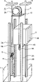
Fig. 1 is the cutaway drawing of hoisting crane of the jacking system of one embodiment of the invention;
Fig. 2 is the front elevation of hoisting crane shown in Figure 1;
Fig. 3 is the three-dimensional view that jacking system of the present invention is shown;
Fig. 4 is the cutaway drawing of hoisting crane of the jacking system of another embodiment of the present invention;
Fig. 5 is the front elevation that the arrangement structure of actual equipment and jacking system of the present invention is shown;
Fig. 6 is the amplification plan view of Fig. 5; And
Fig. 7 is the cutaway drawing of hoisting crane of the jacking system of further embodiment of this invention.
The specific embodiment
Below with reference to Fig. 1 to 3 explanation one embodiment of the present of invention.
Pair of guide rails 2A, 2B guiding boxes and baskets 3 can lifting on above-below direction, so that boxes and baskets stand upright on the certain distance position in the lift well 1.Boxes and baskets 3 have the boxes and baskets door 3D of passenger's use and a pair of leading sheave 4A on the two width sides, the bolster of 4B bottom boxes and baskets.Main cable 5 is last and pass the bottom of boxes and baskets 3 around leading sheave 4A, 4B.One end of main cable 5 for example is bearing on the beam of lift well 1 top side.
In addition, on lift well 1, weight guide 7A, 7B have a parallel distance between vertical direction and boxes and baskets guide rail 2A, 2B, and bootable thus counterweight 8 moves at vertical direction.The axle of guide wheel 9 is bearing in the top of counterweight 8, and the other end of above-mentioned main cable 5 is on guide wheel 9 and be bearing on the beam of top side.
On the other hand, on the top of lift well 1, a supporting base 10 is installed and a hoisting crane 11 is bearing on the supporting base 10.Hoisting crane 11 has a sheave 26, and leading sheave 4A, the 4B of main cable 5 by boxes and baskets 3 bottoms guides the guide wheel 9 of counterweight 8 on the sheave 26 into.
The concrete composition of hoisting crane 11 then is described.Hoisting crane 11 basic building are on the base 12 that is fixed in supporting base 10.The fixed frame 13 that promptly has upright plane 14 is arranged on the base 12, and perpendicular to uprightly plane 14 and horizontally extending anchor shaft 15 are to be stretched out by fixed frame 13 cantilevers to form.Anchor shaft 15 has a major diameter part 15a in upright plane 14 sides, and in free end side one small diameter portion 15b is arranged.One swivel mount 16 can be rotated to support on the small diameter portion 15b of anchor shaft 15 by bearing 18A, 18B.
Swivel mount 16 constitutes a cylindrical shape bottom having or cup-shaped by plate-like bottom 17 with at the perisporium 19 that its circumference forms, and 17 central authorities form a bearing retaining part 18 in the bottom.Swivel mount 16 can be rotated to support on by bearing 18A, 18B on the small diameter portion 15b of anchor shaft 15, the perforate side periphery of perisporium 19 thus, and promptly 19 of perisporium perforate side periphery is arranged to equidistantly the upright plane 14 near fixed frame 13.For the stable rotation of swivel mount 16 will be arranged to bearing 18A, 18B to have axially spaced-apart between them.Each all becomes coaxial line with the shaft centre line of anchor shaft 15 outer peripheral face 20 of the bearing retaining part 18 of swivel mount 16 and the inner and outer circumferential surfaces of perisporium 19.
In this manner with anchor shaft 15 coaxial lines the swivel mount 16 that is supported a rotor 21 was bearing on the interior week of perisporium 19.Rotor 21 can be gone up in the interior week by a plurality of permanent magnets being bonded in periphery wall 19 or the rotor core that will have a plurality of embedding permanent magnets is embedded in going up in interior week of perisporium 19 and constitutes.
The stator 22 that has diameter clearance with respect to rotor 21 is fixed on the fixed frame 13.Stator 22 comprises that having stator core 23 and the winding of having decided on stator core that the lamination silicon steel plate in the hole of being passed through by the said fixing axle makes by central authorities is formed.Stator 22 is fixed on the fixed frame 13 by support 25.
The one outer electrical motor that makes the transition is made up of the fixed frame of rotor 21, stator 22, supporting stator 22, the swivel mount 16 of supporting rotor 21 and the anchor shaft 15 of supporting swivel mount 16.Here, the outer radius portion of electrical motor is the outer peripheral face of perisporium 19 of the swivel mount 16 of supporting rotor 21.
In addition, swivel mount have be fixed on contain promptly be fixed on swivel mount on 17 outsides, round-ended cylinder shape bottom with fixed frame 13 opposite sides on sheave 26.Be sheave 26 be utilize the bearing retaining part that on swivel mount 16 bottoms 17, forms 18 outer peripheral faces 20 fixing with anchor shaft 15 coaxial lines.In such structure, because swivel mount 16 constitutes the rotating part of electrical motor, sheave 26 is mounted and fixed on the rotating part of electrical motor.For reducing the size of electrical motor, sheave 26 forms like this: make the external diameter of the diameter of cable trough 26G less than electrical motor, i.e. the outer peripheral face of swivel mount 16 perisporiums 19.Sheave 26 usefulness screws 27 screw in the bottom of swivel mount 16 and are fixed on the swivel mount 17.In addition, on the middle body of sheave 26, form a mounting hole 28 so that mounting hole 28 centers are identical with the center of cable trough 26G, and the diameter of mounting hole 28 to have such size be that bearing retaining part 18 can insert in the hole and has very little gap with the outer peripheral face of bearing retaining part 18.Therefore, because the outer peripheral face of bearing retaining part 18 is made the shaft centre line coaxial line with anchor shaft 15, as long as it is promptly consistent with the axle center of anchor shaft 15 sheave 26G to be installed to the center of cable trough 26G on the outer peripheral face of bearing retaining part 18 of swivel mount 16.
In addition, sheave 26 has V-rope groove 26G be driven the essential friction force that obtains when making boxes and baskets 3 and counterweight 8 liftings 5 of main cables with convenient main cable 5 on sheave 26.A kind of material with fabulous resistance to abrasion that is different from swivel mount 16 of sheave 26 usefulness is made, although so that it produces friction with main cable 5 and can use for prolonged period of time.
In addition, about sheave, as long as it has coiling main cable 5 and drives its function, then its shape is not limited to a kind of given shape, and for example, it can cut out on the outer peripheral face of cable trough 26G and make cylindrical shape.
Except above-mentioned, on the circumference of the perisporium 19 of swivel mount 16, be provided with drg 29.Drg 29 comprise a pair of its each end be supported on pivotally brake control lever 30A, 30B on the base 12, by axle be bearing on brake control lever 30A, the 30B centre portion with in the face of brake block 31A, the 31B of perisporium 19 outer peripheral faces, a pair of other end and opposed facing brake axle 32A, the 32B that passes brake control lever 30A, 30B, make brake axle 32A, 32B overcome retarding spring 33A, 33B when being arranged to attract retarding spring 33A, the 33B of brake axle 32A, 32B and work to divide the electromagnet of opening 34.Because the perisporium of swivel mount 16 that will be relative with brake block 31A, 31B just constitutes a rotating cylinder type drg as rotating cylinder.
The perisporium 19 of swivel mount 16 is owing to also have wearing and tearing to a certain degree with brake block 31A, 31B moving contact, yet, owing to just make boxes and baskets 3 enough reductions of speed and stop preceding generation, be very little with this abrasion loss of comparing owing to the abrasion loss that contacts of pulley 26 and main cable 5 with the cliding friction of the perisporium 19 of brake block 31A, 31B.Therefore, the cable wire tube of changing than per 5 to 10 years once as the stage of replacement of the perisporium 19 of the swivel mount 16 of the rotating cylinder of drg 29 26 is long.
In addition, the bottom 17 from swivel mount 16 is arranged on the space that is surrounded by fixed frame 13 and swivel mount 16 with the extended cylindrical part 35 in anchor shaft 15 coaxial line ground.Cylindrical part extends into the upright plane 14 of traverses fixed framework 13 squarely, and is furnished with a plurality of slits (not shown) in its circumferencial direction compartment of terrain.Thereby sensor 36 is bearing on the fixed frame 13 from both sides the slit of cylinder 35 is clipped in the middle and detects the rotating speed of electrical motor.
In addition, because cylindrical part and sensor 36 are answered free from dust, invade to prevent dust at the upright plane 14 and the middle hermetic unit that is formed with of perisporium 19 1 ends of fixed frame 13.As the concrete structure of sealing part, thus can consider to adopt by be arranged on structure that sealing member 37 that upright plane 14 and perisporium 19 slide relative to one another on any one prevents that dust from invading or by make a partition wall 14R from stretching out adjacent to upright plane 14 sides of perisporium 19 ends so that the whole circumference of the inner peripheral surface of relative perisporium 19 and between them, leave the structure that little gap prevents the dust intrusion.Yet place of installing according to jacking system and environment can be with sealing member 37 and partition wall 14R in conjunction with using or only using one among sealing member 37 and the partition wall 14R to prevent that dust from entering.
In above-mentioned structure,, disassemble for checking with regard to need not because the maintenance inspection of drg 29 can be arrived by eye-observation from the outside.Yet,, so just can under situation about not disassembling, carry out the maintenance inspection of electrical motor, sensor 36 etc. owing to do the size of hoisting crane 11 little.Yet according to present embodiment of the present invention, the motor rotor 21, cylindrical part 35 and the sheave that are fixed on separately on the swivel mount 16 can be by extracting swivel mount 16 and disengaging simultaneously out from anchor shaft 15 towards the opposite side of fixed frame 13.After swivel mount 16 is extracted out from anchor shaft 15, when the maintenance inspection that will just can carry out when carrying out maintenance inspection them by fixed frame 13 fixed supported motor stators 22 and sensor 36, and as the replaceable part of needs.On the other hand, because the cup-shaped inboard of the swivel mount 16 that is drawn out of can be observed by eyes, just can carry out the maintenance inspection of rotor 21 and cylindrical part 35 and the replacing of part.
After maintenance inspection, by the order opposite swivel mount 16 is installed on the anchor shaft 15, thus complete operation with dismounting.
In addition, owing to cable trough 26G uses sheave main cable 5 slips relatively in some cases of wearing and tearing over a long time at it, should change sheave 26 this moment.Yet, according to present embodiment of the present invention, just cable trough 26G and anchor shaft 15 coaxial lines are fixed and made to new sheave 26 from the outer peripheral face 20 of swivel mount 16 extraction sheaves 26, employing bearing retaining part 18 as guiding to insert new sheave 26 and screw 27 is screwed in swivel mount 16 by throwing off screw 27.
According to present embodiment of the present invention, just can carry out the dismounting of hoisting crane 11 and the axis alignment after the assembling by this way easily, so just can shorten the work-hours of mounting or dismounting.
Fig. 4 illustrates another embodiment of the present invention.Different with previous embodiment is the circumferential shapes of swivel mount 16, and the label identical with Fig. 1 to 3 represented same part, thereby omits the repeat specification to them.
According to present embodiment, vertical horizontal right disk 38 with anchor shaft 15 is to form on the extension of the bottom 17 of swivel mount 16 peripheries 19, and arrange that a well-known electromagnetism disk brake (not shown) to clamp disk 38, can provide the hoisting crane 11 that has the electromagnetism disk brake thus.
In addition, on the perforate side of the perisporium 19 of swivel mount 16, form a disk 39 to replace disk 38, and arrange that an electromagnetism disk brake (not shown) is relative with disk 39, disk 39 becomes the annular arrangement ring stiffener of thickening thickness thereby the rigidity that can improve perforate side perisporium 19 thus, so just can make the thickness of perisporium 19 do thinlyyer.
Then, Fig. 5 and 6 illustrates a kind of optimal placement of equipment and at magnet crane in-to-in device.In Fig. 5 and 6, represent that with label identical among Fig. 1 to 3 same part omits its repeat specification thus.
In this magnet crane inside, a pair of boxes and baskets guide rail 2A, 2B are arranged on the both sides of boxes and baskets 3 at certain intervals at the Width parallel with boxes and baskets door 3D.In addition, leading sheave 4A, 4B are bearing on the bottom of boxes and baskets 3 at described same Width at certain intervals by axle, and leading sheave 4A, 4B with respect to boxes and baskets guide rail 2A, 2B is arranged in the opposite side of boxes and baskets door 3D on.
In the space between a sidewall of the leading sheave side 4A of boxes and baskets 3 and lifting shaft 1, a pair of weight guide 7A, 7B erectly arrange with 8 liftings of guiding counterweight at certain intervals along the import and export direction of boxes and baskets 3.In addition, see in the plane that this is that relative boxes and baskets guide rail 2A is arranged on the opposite side of boxes and baskets door 3D to weight guide 7A, 7B.
On the other hand, see in the plane that it is overlapping or adjacent to the guide wheel 4A end of stretching out the outside from boxes and baskets 3 sidewalls that they are arranged to diametric(al) one end of sheave 26 of hoisting crane 11.The side surface of sheave 26 is arranged with this septal direction to weight guide 7A, 7B with paralleling, and its diametric(al) other end is arranged on the weight guide 7B side.
On the top of counterweight 8, guide wheel 9 is supported by axle.Guide wheel 9 is arranged in the face of the septal direction of weight guide 7A, 7B tilts, and a diameter direction end of guide wheel 9 is overlapping or adjacent to another diametric(al) end of sheave 26 like this.
In above-mentioned relation for boxes and baskets 3, be furnished with counterweight 8, each leading sheave 4A, 4B, 9 and sheave 26, they can be installed in the narrow inboard of lift well 1 effectively like this, even and hoisting crane be mounted in lift well 1 inboard, also needn't increase the zone of lift well 1.
Hoisting crane 11 in the various embodiments described above is to adopt a kind of outer rotation electrical motor, its rotor 21 in swivel mount 16 inboards is to be arranged on the overall diameter side of stator 22, yet, even hoisting crane 11 adopts a kind of interior rotation electrical motor, its rotor 21 is to be arranged on the interior diameter side of stator 22, as shown in Figure 7, then also can obtain same effect.
Rotation electrical motor situation in above-mentioned, by being positioned at the holding element 22Y on the stator 22 overall diameter faces, stator 22 is bearing on the fixed frame 13, thereby makes the neighboring part that partly is holding element 22Y as the overall diameter of electrical motor.
As mentioned above, the sheave that is used for the hoisting crane of jacking system of the present invention is mounted in swivel mount, and this swivel mount is that a rotating part by the anchor shaft supporting is formed.Yet, when hoisting crane adopts its rotor to be the situation of the electrical motor of body plan on S. A., then sheave is installed on the S. A. and it is fixed and also be considered on it be fine, yet, because the diameter of S. A. is little, therefore removably sheave being installed in structurally has certain trouble on the S. A., when this situation, just sheave must be removably mounted on the rotating part of electrical motor rather than on S. A..
As mentioned above, according to the present invention, just can provide a kind of jacking system that has the hoisting crane that to finish dismounting easily and install.
Claims (16)
1. jacking system, have one and be installed in the hoisting crane of lift well inboard and the boxes and baskets by the cable wire lifting on the sheave of described hoisting crane, it is characterized in that, described hoisting crane have one drive described sheave and comprise the electrical motor of an anchor shaft and one by described anchor shaft supporting with can be around the rotating part of described anchor shaft rotation; Described sheave has receipts around cable wire part and in described anchor shaft separately and be removably mounted on the described electrical motor rotating part, so that described receipts become coaxial line around the cable wire part with described anchor shaft.
2. jacking system as claimed in claim 1 is characterized in that, its diameter of described sheave is less than the external diameter of described electrical motor.
3. jacking system as claimed in claim 1 is characterized in that, described sheave be by be better than described rotating part material make.
4. a jacking system that is provided with hoisting crane, it comprises a fixed frame, one anchor shaft by described fixed frame supports, one by the rotatably mounted swivel mount of anchor shaft, the sheave that the electrical motor and of one body plan between described swivel mount and described fixed frame rotates with described swivel mount, and be made into make cable wire on the described sheave with lifting one boxes and baskets, it is characterized in that: described sheave has receipts around cable wire part and be removably mounted on the middle body of described swivel mount, action by described electrical motor is rotated around described anchor shaft, so that described receipts become coaxial line around the cable wire part with described anchor shaft.
5. a jacking system that is provided with hoisting crane, it comprises a fixed frame, one anchor shaft by described fixed frame supports, one by the rotatably mounted swivel mount of described anchor shaft, the sheave that the electrical motor and of one body plan between described swivel mount and described fixed frame rotates with described swivel mount, and be made into make cable wire on the described sheave with lifting one boxes and baskets, it is characterized in that: described electrical motor has and is arranged through an opposed facing rotor in a radial air gap and a stator, have its diameter and be removably mounted on the described swivel mount, so that described receipts become coaxial line around the cable wire part with described anchor shaft less than the receipts of the external diameter of swivel mount described sheave around the cable wire part.
6. a jacking system that is provided with hoisting crane, it comprises a fixed frame, one anchor shaft by described fixed frame supports, one by the rotatably mounted swivel mount of described anchor shaft, the sheave that the electrical motor and of one body plan between described swivel mount and described fixed frame rotates with described swivel mount, and be made into make cable wire on the described sheave with lifting one boxes and baskets, it is characterized in that: described swivel mount is made into the cylindrical shape with bottom, and is made up of a peripheral part that is stretched out by the peripheral, axial of described base section perpendicular to the base section of described anchor shaft and; The bottom center of described swivel mount is supported by described anchor shaft, has a described sheave of receiving around the cable wire part and is removably mounted on the bottom of described swivel mount, so that described receipts become coaxial line around the cable wire part with described anchor shaft.
7. jacking system as claimed in claim 6, it is characterized in that, a drg that is used to described swivel mount is stopped operating is arranged to described electrical motor overlapping, and described swivel mount and described fixed frame be arranged to make the described upstanding portion of the aperture portion branch of the described swivel mount on an opposite side with described bottom adjacent to described fixed frame, and this upstanding portion is vertical horizontal in described anchor shaft.
8. its cable wire is on the sheave that is installed in the hoisting crane on the lift well inboard and boxes and baskets drive the jacking system of lifting by cable wire, it is characterized in that:
Described hoisting crane comprise an anchor shaft by a fixed frame horizontal supporting, one by axle can be rotated to support on the described anchor shaft have the bottom columnar swivel mount, the electrical motor of a body plan between described swivel mount and described fixed frame, the drg that a sheave and that rotates with described swivel mount stops operating described swivel mount;
Described electrical motor and drg are arranged to mutual axial overlap, and
Have a described sheave of receiving around the cable wire part and be removably mounted on the described swivel mount, so that described receipts become coaxial line around the cable wire part with described anchor shaft.
9. jacking system as claimed in claim 7 is characterized in that, described sheave is made into its diameter less than described electrical motor and be to be made by the material that a kind of resistance to abrasion is better than described swivel mount.
10. a jacking system that is provided with hoisting crane, it comprise an anchor shaft by fixed frame supports, one by axle can be rotated to support on electrical motor between described swivel mount and described fixed frame of swivel mount on the described anchor shaft, a body plan, the sheave that rotates with described swivel mount and the drg that described swivel mount is stopped operating, described electrical motor and described drg are arranged to mutual axial overlap, and be made into make cable wire on the described sheave with lifting one boxes and baskets, it is characterized in that:
Described swivel mount be made into one have the cylindrical shape of bottom and have cylindrical shape part that a base section perpendicular to described anchor shaft, stretches out from the peripheral, axial of described base section with one on the relative side with described base section and the perforate end on the side of described fixed frame;
The central authorities of the base section of described bottom with cylindrical shape swivel mount are rotatably mounted by anchor shaft;
Described bottom with columnar base section have a protrusion that stretches out from it and have one with the outer peripheral face of described anchor shaft coaxial line;
On described sheave, be formed with a mounting hole, also can be equipped with described outer peripheral face with bottom of columnar base section with cable trough coaxial line with described sheave; And
The outer peripheral face of the bottom of described sheave by will having columnar base section is fitted in the described mounting hole and is removably mounted on the described swivel mount.
11. one is provided with the jacking system of hoisting crane, it comprises an anchor shaft by fixed frame supports, a sheave that rotates by electrical motor between described swivel mount and described fixed frame of the rotatably mounted swivel mount of described anchor shaft, a body plan, with described swivel mount and the drg that described swivel mount is stopped operating, described electrical motor and described drg are arranged to mutual axial overlap, and be made into make cable wire on the described sheave with lifting one boxes and baskets, it is characterized in that:
Described fixed frame has a vertical horizontal upstanding portion to described anchor shaft;
Described swivel mount is made into bottom with cylindrical shape, have a cylindrical shape part and the perforate part on an opposite side with described base section of stretching out from the peripheral, axial of described base section with the vertical base section of described anchor shaft,, and is arranged to make the described upstanding portion of described aperture portion branch adjacent to described fixed frame;
Have receipts and be removably mounted on the base section of described swivel mount, so that described receipts become coaxial line around the cable wire part with described anchor shaft around the described sheave of cable wire part; And
One sealing is arranged between the described fixed frame of perforate partial sum of described swivel mount.
12. each the described jacking system as claim 4 to 11 is characterized in that, described anchor shaft is to be made into by described fixed frame cantilever.
13. a jacking system is characterized in that:
One boxes and baskets that guided up and down are arranged in the inside of lift well;
One drives the hoisting crane of described boxes and baskets lifting, when the space between the wall of a boxes and baskets sidewall that is mounted in the described boxes and baskets Width on the plane when Jing Ding sees and described lift well;
Described hoisting crane has a rotating part and the sheave that an electrical motor, is rotated on motor reel by the action drives of described electrical motor; Described sheave has one to be received around the cable wire part and is removably mounted on the described rotating part on an outer side position of more described motor reel, so that described receipts become coaxial line around the cable wire part with described motor reel; And the plane of rotation of described sheave is the sidewall that is parallel to described lift well;
One counterweight that is directed up and down is arranged under the described hoisting crane; And
Cable wire around described boxes and baskets and described counterweight is on described sheave.
14. jacking system as claimed in claim 13 is characterized in that:
Described boxes and baskets have a pair of leading sheave and are bearing on the both sides of described boxes and baskets bottom width direction by axle;
Described sheave be diametric(al) one end of one of leading sheave to be arranged in the plane at a diametric end adjacent to this;
Above-mentioned counterweight has the guide wheel by the axle supporting, and it is inclined to is that described guide wheel contacts at the diametric other end with described sheave at a diametric end; And
Described cable wire is on described sheave, and the two ends of described each leading sheave and cable wire are to be fixed on the top of described well.
15. each described jacking system as claim 1 to 10 and 13, it is characterized in that described electrical motor comprises that one has the rotor that is fixed on the permanent magnet on a rotating part or the swivel mount and one and is arranged on a fixed part or the fixed frame to keep the stator of an a. g. with respect to described rotor.
16. jacking system as claimed in claim 12, it is characterized in that described electrical motor comprises that one has the rotor that is fixed on the permanent magnet on a rotating part or the swivel mount and one and is arranged on a fixed part or the fixed frame to keep the stator of an a. g. with respect to described rotor.
Applications Claiming Priority (3)
| Application Number | Priority Date | Filing Date | Title |
|---|---|---|---|
| JP191238/1998 | 1998-07-07 | ||
| JP19123898A JP3725979B2 (en) | 1998-07-07 | 1998-07-07 | Elevator equipment |
| JP191238/98 | 1998-07-07 |
Publications (2)
| Publication Number | Publication Date |
|---|---|
| CN1241528A CN1241528A (en) | 2000-01-19 |
| CN1106338C true CN1106338C (en) | 2003-04-23 |
Family
ID=16271207
Family Applications (1)
| Application Number | Title | Priority Date | Filing Date |
|---|---|---|---|
| CN99110155A Expired - Fee Related CN1106338C (en) | 1998-07-07 | 1999-06-30 | Elevator apparatus |
Country Status (5)
| Country | Link |
|---|---|
| EP (1) | EP0970912B2 (en) |
| JP (1) | JP3725979B2 (en) |
| CN (1) | CN1106338C (en) |
| DE (1) | DE69921555T3 (en) |
| HK (1) | HK1023550A1 (en) |
Cited By (3)
| Publication number | Priority date | Publication date | Assignee | Title |
|---|---|---|---|---|
| CN102066228B (en) * | 2008-06-16 | 2013-05-15 | 株式会社明电舍 | Flat hoist for elevator |
| CN105293334A (en) * | 2014-06-17 | 2016-02-03 | 三菱电机株式会社 | Rotating body |
| CN106458522A (en) * | 2014-06-05 | 2017-02-22 | 三菱电机株式会社 | Elevator hoist and method for fastening rope sheave for elevator hoist |
Families Citing this family (29)
| Publication number | Priority date | Publication date | Assignee | Title |
|---|---|---|---|---|
| JP2001226058A (en) * | 2000-02-10 | 2001-08-21 | Mitsubishi Electric Corp | Door device of elevator |
| ES2220798T5 (en) * | 2000-09-27 | 2010-05-12 | Inventio Ag | ELEVATOR WITH MOTOR UNIT LATERALLY AVAILABLE ON THE TOP OF THE ELEVATOR BOX. |
| JP2003106348A (en) * | 2001-09-28 | 2003-04-09 | Meidensha Corp | Brake device and hoist |
| JP2003104666A (en) | 2001-09-28 | 2003-04-09 | Meidensha Corp | Hoisting machine and elevator device |
| IL180964A (en) | 2002-09-05 | 2010-11-30 | Inventio Ag | Drive engine for a lift installation and method of mounting a drive engine |
| KR100451317B1 (en) * | 2002-09-17 | 2004-10-06 | 현대엘리베이터주식회사 | Slimming type traction machine |
| FR2858723B1 (en) * | 2003-08-08 | 2005-12-30 | Leroy Somer Moteurs | ELECTRIC MACHINE, IN PARTICULAR FOR ELEVATOR |
| JP4439470B2 (en) * | 2003-08-21 | 2010-03-24 | 三菱電機株式会社 | Thin hoisting machine for elevator |
| JPWO2005068338A1 (en) * | 2004-01-15 | 2007-08-23 | 三菱電機株式会社 | Elevator hoisting machine |
| JP4525197B2 (en) * | 2004-06-17 | 2010-08-18 | 株式会社明電舎 | Elevator hoisting machine |
| EP1790609B1 (en) * | 2004-07-29 | 2014-03-05 | Mitsubishi Denki Kabushiki Kaisha | Hoist for elevator |
| JP4365345B2 (en) * | 2004-10-20 | 2009-11-18 | 三菱電機株式会社 | Hoisting machine and its installation method |
| KR100705144B1 (en) * | 2005-04-20 | 2007-04-09 | 미쓰비시덴키 가부시키가이샤 | Thin hoist for elevator |
| KR100703461B1 (en) * | 2006-03-03 | 2007-04-03 | 미쓰비시덴키 가부시키가이샤 | Winch for elevator |
| DE102006052767B4 (en) * | 2006-11-09 | 2012-11-08 | Robert Bosch Gmbh | External rotor motor with brake |
| JP5255785B2 (en) * | 2007-06-15 | 2013-08-07 | 株式会社日立産機システム | Elevator hoisting machine |
| JP5380837B2 (en) * | 2007-12-27 | 2014-01-08 | 株式会社明電舎 | Elevator hoisting machine |
| JP4900971B2 (en) * | 2008-11-05 | 2012-03-21 | 東芝エレベータ株式会社 | Elevator system |
| JP2010193607A (en) * | 2009-02-18 | 2010-09-02 | Mitsubishi Electric Corp | Rotary electric machine, manufacturing method thereof, and hoist |
| JP5358282B2 (en) * | 2009-05-14 | 2013-12-04 | 株式会社日立製作所 | Elevator hoisting machine and elevator device |
| CN101987711B (en) * | 2009-07-30 | 2013-02-13 | 包文丽 | Tractor used for elevator |
| JP2011063434A (en) * | 2009-09-18 | 2011-03-31 | Toshiba Elevator Co Ltd | Brake device for elevator hoisting machine, and method for adjusting the same |
| JP5048802B2 (en) * | 2010-03-26 | 2012-10-17 | 株式会社日立製作所 | Thin hoisting machine for elevator and elevator device |
| JP2011241062A (en) * | 2010-05-19 | 2011-12-01 | Hitachi Ltd | Elevator apparatus |
| CN102030245B (en) * | 2010-12-31 | 2012-05-02 | 厦门康柏机械集团有限公司 | Tilting elevator cage |
| JP5462195B2 (en) * | 2011-01-25 | 2014-04-02 | 株式会社日立製作所 | Elevator |
| US10384914B2 (en) * | 2015-09-10 | 2019-08-20 | Otis Elevator Company | Elevator support structure |
| JP6134952B1 (en) * | 2015-12-03 | 2017-05-31 | 株式会社明電舎 | Hoisting machine |
| CN109850725B (en) * | 2018-12-24 | 2023-11-21 | 菱王电梯有限公司 | Drum type double-support combined high-speed heavy-load traction machine |
Citations (3)
| Publication number | Priority date | Publication date | Assignee | Title |
|---|---|---|---|---|
| JPS63277190A (en) * | 1987-05-07 | 1988-11-15 | 三菱電機株式会社 | Winding machine for elevator |
| JPH09506237A (en) * | 1994-04-07 | 1997-06-17 | コネ オサケ ユキチュア | Elevator machinery |
| CN1212948A (en) * | 1997-09-26 | 1999-04-07 | 东芝株式会社 | Electric elevator |
Family Cites Families (8)
| Publication number | Priority date | Publication date | Assignee | Title |
|---|---|---|---|---|
| US1171964A (en) * | 1914-08-01 | 1916-02-15 | Alonso B Lee | Electric motor. |
| AU580453B2 (en) † | 1985-11-04 | 1989-01-12 | Johns Perry Industries Pty. Ltd. | Lift sheave |
| JPH0745315B2 (en) * | 1988-08-26 | 1995-05-17 | 三菱電機株式会社 | Hoisting machine |
| AU7075094A (en) * | 1993-06-28 | 1995-01-17 | Kone Oy | Elevator machinery |
| FI941596A (en) † | 1994-04-07 | 1995-10-08 | Kone Oy | The engine of an elevator |
| DE19720479A1 (en) † | 1997-05-16 | 1998-11-19 | Baumueller Nuernberg Gmbh | Lifting device, in particular elevator, with an electric motor and use of the electric motor |
| DE19739001C1 (en) * | 1997-09-06 | 1998-10-15 | Ziehl Abegg Gmbh & Co Kg | Lift drive arrangement with horizontal shaft type electric drive motor |
| DE19815962A1 (en) * | 1998-04-09 | 1999-10-14 | Atb Antriebstechnik Ag | Electrical machine, in particular for elevator drives |
-
1998
- 1998-07-07 JP JP19123898A patent/JP3725979B2/en not_active Expired - Lifetime
-
1999
- 1999-06-30 CN CN99110155A patent/CN1106338C/en not_active Expired - Fee Related
- 1999-07-01 DE DE1999621555 patent/DE69921555T3/en not_active Expired - Lifetime
- 1999-07-01 EP EP99112612A patent/EP0970912B2/en not_active Expired - Lifetime
-
2000
- 2000-05-04 HK HK00102722A patent/HK1023550A1/en not_active IP Right Cessation
Patent Citations (3)
| Publication number | Priority date | Publication date | Assignee | Title |
|---|---|---|---|---|
| JPS63277190A (en) * | 1987-05-07 | 1988-11-15 | 三菱電機株式会社 | Winding machine for elevator |
| JPH09506237A (en) * | 1994-04-07 | 1997-06-17 | コネ オサケ ユキチュア | Elevator machinery |
| CN1212948A (en) * | 1997-09-26 | 1999-04-07 | 东芝株式会社 | Electric elevator |
Cited By (5)
| Publication number | Priority date | Publication date | Assignee | Title |
|---|---|---|---|---|
| CN102066228B (en) * | 2008-06-16 | 2013-05-15 | 株式会社明电舍 | Flat hoist for elevator |
| CN106458522A (en) * | 2014-06-05 | 2017-02-22 | 三菱电机株式会社 | Elevator hoist and method for fastening rope sheave for elevator hoist |
| CN106458522B (en) * | 2014-06-05 | 2018-11-13 | 三菱电机株式会社 | The fastening method of the rope sheave of elevator traction machine and elevator traction machine |
| CN105293334A (en) * | 2014-06-17 | 2016-02-03 | 三菱电机株式会社 | Rotating body |
| CN105293334B (en) * | 2014-06-17 | 2017-11-10 | 三菱电机株式会社 | Rotary body |
Also Published As
| Publication number | Publication date |
|---|---|
| CN1241528A (en) | 2000-01-19 |
| JP3725979B2 (en) | 2005-12-14 |
| HK1023550A1 (en) | 2000-09-15 |
| DE69921555T3 (en) | 2008-03-06 |
| EP0970912B2 (en) | 2007-08-08 |
| EP0970912A2 (en) | 2000-01-12 |
| EP0970912A3 (en) | 2002-03-06 |
| DE69921555D1 (en) | 2004-12-09 |
| JP2000016727A (en) | 2000-01-18 |
| EP0970912B1 (en) | 2004-11-03 |
| DE69921555T2 (en) | 2005-12-08 |
Similar Documents
| Publication | Publication Date | Title |
|---|---|---|
| CN1106338C (en) | Elevator apparatus | |
| CN1226178C (en) | Lifter and elevator system using same | |
| CN1107017C (en) | Elevator machinery | |
| US9663325B2 (en) | Braking apparatus and elevator hoisting machine that uses same | |
| CN100545070C (en) | Elevator hoist | |
| JPH09156855A (en) | Elevator device | |
| CN100354545C (en) | Brake device and hoist for elevator | |
| CN100337899C (en) | Hoist for elevator | |
| CN1309650C (en) | Driver of elevator | |
| JPWO2004071926A1 (en) | Elevator equipment | |
| CN1926052A (en) | Traction machine for elevator | |
| KR100441043B1 (en) | Slimming type traction machine | |
| CN1849258A (en) | Elevator apparatus | |
| KR100784923B1 (en) | Traction device for elevator | |
| CN1856437A (en) | Hoist for elevator | |
| KR100790654B1 (en) | Elevator hoist | |
| KR20070105150A (en) | Traction device for elevator | |
| KR100451316B1 (en) | Slimming type traction machine | |
| JP4284123B2 (en) | Hoisting machine and elevator device equipped with hoisting machine | |
| KR200421632Y1 (en) | Traction device for elevator | |
| JP4032071B2 (en) | Elevator equipment | |
| CN1310820C (en) | Hoisting machine for elevator | |
| JP3787570B2 (en) | Elevator equipment | |
| KR20040025724A (en) | Slimming type traction machine | |
| JP2018177434A (en) | Hoisting machine for elevator |
Legal Events
| Date | Code | Title | Description |
|---|---|---|---|
| C10 | Entry into substantive examination | ||
| SE01 | Entry into force of request for substantive examination | ||
| C06 | Publication | ||
| PB01 | Publication | ||
| C14 | Grant of patent or utility model | ||
| GR01 | Patent grant | ||
| CF01 | Termination of patent right due to non-payment of annual fee |
Granted publication date: 20030423 Termination date: 20180630 |
|
| CF01 | Termination of patent right due to non-payment of annual fee |