CN110492287B - Connector with a locking member - Google Patents
Connector with a locking member Download PDFInfo
- Publication number
- CN110492287B CN110492287B CN201910899488.9A CN201910899488A CN110492287B CN 110492287 B CN110492287 B CN 110492287B CN 201910899488 A CN201910899488 A CN 201910899488A CN 110492287 B CN110492287 B CN 110492287B
- Authority
- CN
- China
- Prior art keywords
- contact
- orientation
- edge
- width direction
- support portion
- Prior art date
- Legal status (The legal status is an assumption and is not a legal conclusion. Google has not performed a legal analysis and makes no representation as to the accuracy of the status listed.)
- Active
Links
Images


Classifications
-
- H—ELECTRICITY
- H01—ELECTRIC ELEMENTS
- H01R—ELECTRICALLY-CONDUCTIVE CONNECTIONS; STRUCTURAL ASSOCIATIONS OF A PLURALITY OF MUTUALLY-INSULATED ELECTRICAL CONNECTING ELEMENTS; COUPLING DEVICES; CURRENT COLLECTORS
- H01R24/00—Two-part coupling devices, or either of their cooperating parts, characterised by their overall structure
- H01R24/60—Contacts spaced along planar side wall transverse to longitudinal axis of engagement
-
- H—ELECTRICITY
- H01—ELECTRIC ELEMENTS
- H01R—ELECTRICALLY-CONDUCTIVE CONNECTIONS; STRUCTURAL ASSOCIATIONS OF A PLURALITY OF MUTUALLY-INSULATED ELECTRICAL CONNECTING ELEMENTS; COUPLING DEVICES; CURRENT COLLECTORS
- H01R13/00—Details of coupling devices of the kinds covered by groups H01R12/70 or H01R24/00 - H01R33/00
- H01R13/02—Contact members
- H01R13/22—Contacts for co-operating by abutting
- H01R13/24—Contacts for co-operating by abutting resilient; resiliently-mounted
- H01R13/2464—Contacts for co-operating by abutting resilient; resiliently-mounted characterized by the contact point
- H01R13/2492—Contacts for co-operating by abutting resilient; resiliently-mounted characterized by the contact point multiple contact points
-
- H—ELECTRICITY
- H01—ELECTRIC ELEMENTS
- H01R—ELECTRICALLY-CONDUCTIVE CONNECTIONS; STRUCTURAL ASSOCIATIONS OF A PLURALITY OF MUTUALLY-INSULATED ELECTRICAL CONNECTING ELEMENTS; COUPLING DEVICES; CURRENT COLLECTORS
- H01R13/00—Details of coupling devices of the kinds covered by groups H01R12/70 or H01R24/00 - H01R33/00
- H01R13/40—Securing contact members in or to a base or case; Insulating of contact members
- H01R13/405—Securing in non-demountable manner, e.g. moulding, riveting
- H01R13/415—Securing in non-demountable manner, e.g. moulding, riveting by permanent deformation of contact member
-
- H—ELECTRICITY
- H01—ELECTRIC ELEMENTS
- H01R—ELECTRICALLY-CONDUCTIVE CONNECTIONS; STRUCTURAL ASSOCIATIONS OF A PLURALITY OF MUTUALLY-INSULATED ELECTRICAL CONNECTING ELEMENTS; COUPLING DEVICES; CURRENT COLLECTORS
- H01R2107/00—Four or more poles
Landscapes
- Coupling Device And Connection With Printed Circuit (AREA)
Abstract
A connector is capable of mating with a mating connector in a front-rear direction. The connector includes at least one contact and a retention member. At least one contact has a first support portion, a second support portion, a first contact portion, a second contact portion, and a coupling portion. The first support portion has a first edge in the width direction. The coupling portion has an upper main body portion and an upper bent portion. The upper body has an upper front wide portion, an upper front narrow portion, and an upper base. The upper front narrow portion has an edge facing the first orientation. At least one contact has a first boundary portion between a first edge of the first support portion and the upper front wide portion in the front-rear direction. The edge of the upper front narrow portion is positioned beyond the first boundary portion in the second orientation.
Description
The application is a divisional application of an invention patent application with application date of 2017, 8 and 23, application number of 201710728964.1 and name of 'connector'.
Technical Field
The present invention relates to a connector including a contact capable of giving the connector a reduced width-direction dimension.
Background
As shown in fig. 27, japanese patent laid-open No. 2016-110966 (patent document 1) discloses a connector 900 capable of mating with a mating connector (not shown) in a mating direction or in an X direction. The connector 900 includes a plurality of contacts 910, and a retention member 950. Each contact 910 is held by a holding member 950. As shown in fig. 28 and 29, each contact 910 includes a first contact piece 920, a second contact piece 930, a first contact portion 922, a second contact portion 932, and a coupling portion 940. The first contact piece 920 and the second contact piece 930 are arranged in the up-down direction or in the Z direction. The first contact portion 922 is disposed near a free end of the first contact piece 920. The second contact 932 is disposed near the free end of the second contact strip 930. The coupling portion 940 has two side walls 942, 944, two bends 943, 945, and a wall portion 946. The bent portion 943 extends from one end of the side wall 942 in the width direction or the Y direction, and is bent in the Z direction. The bent portion 945 extends from one end of the side wall 944 in the width direction, and is bent in the Z direction. Bends 943, 945 are coupled to each other by wall 946. The first contact strip 920 extends from the side wall 942 in the mating direction or in the X direction. The second contact tab 930 extends from the sidewall 944 in the mating direction or in the X direction.
The dimension of the contact 910 of patent document 1 in the width direction depends on the dimension of the coupling portion 940 in the width direction. In addition, the dimension of each of the first and second contact pieces 920 and 930 in the width direction depends on the dimension of the coupling portion 940 in the width direction. Therefore, while each of the first and second contact pieces 920 and 930 has an increased width-direction dimension, the connector 900 including the contact 910 cannot have a decreased width-direction dimension.
Disclosure of Invention
Accordingly, an object of the present invention is to provide a connector including a contact capable of making the connector have a size reduced in a width direction.
One aspect of the present invention provides a connector capable of mating with a mating connector in a front-to-rear direction. The connector includes at least one contact and a retention member. The holding member holds the at least one contact. The at least one contact has a first support portion, a second support portion, a first contact portion, a second contact portion, and a coupling portion. Each of the first and second supporting portions is elastically deformable. The first contact portion is supported by the first support portion. The second contact portion is supported by the second support portion. Each of the first contact portion and the second contact portion is movable in an up-down direction perpendicular to the front-rear direction. The first support portion has a first edge and a second edge in a width direction perpendicular to both the front-rear direction and the up-down direction. The first edge faces a first orientation in the width direction. The second edge faces a second orientation in the width direction. The first orientation and the second orientation are opposite to each other in the width direction. The coupling portion couples the first support portion and the second support portion to each other. The coupling portion has an upper main body portion and an upper bent portion. The upper body has an upper front wide portion, an upper front narrow portion, and an upper base. The upper front wide portion is immovably fixed to the holding member in the width direction. The first support portion extends forward from the upper front wide portion in the front-rear direction. The upper front narrow portion is positioned between the upper front wide portion and the upper base portion in the front-rear direction. The upper front narrow portion has an edge facing the first orientation. The at least one contact has a first boundary portion located between a first edge of the first support portion and the upper front wide portion in the front-rear direction. The edge of the upper front narrow portion is positioned beyond the first boundary portion in the second orientation. The upper base has an edge facing in a first orientation. The upper bent portion extends from an edge of the upper base portion and is bent downward.
In the contact of the connector of the present invention, an edge of the upper front narrow portion facing the first orientation is positioned beyond a first boundary portion between the first edge of the first support portion and the upper front wide portion in the second orientation. In addition, the upper curved portion extends from an edge of the upper base portion facing the first orientation and curves downward. Therefore, the contact as a whole can have a reduced width-direction dimension while the base portion of the first support portion has an increased width-direction dimension as compared with the contact of patent document 1. Therefore, the connector can have a reduced widthwise dimension.
Drawings
Fig. 1 is an upper side perspective view showing a connector according to a first embodiment of the present invention.
Fig. 2 is an upper perspective view illustrating a connector body included in the connector of fig. 1.
Fig. 3 is a front view showing the connector body of fig. 2.
Fig. 4 is a sectional view showing the connector body of fig. 3 taken along line a-a.
Fig. 5 is a sectional view showing the connector body of fig. 3 taken along line B-B.
Fig. 6 is an upper side perspective view showing a contact included in the connector body of fig. 3, in which a part of the contact is shown enlarged.
Fig. 7 is a side view showing the contact of fig. 6.
Fig. 8 is a plan view showing the contact of fig. 6.
Fig. 9 is another side view showing the contact of fig. 6.
Fig. 10 is a rear view showing the contact of fig. 6.
Fig. 11 is an upper perspective view showing a modification of the contact of fig. 6.
Fig. 12 is another upper perspective view showing the contact of fig. 11.
Fig. 13 is a plan view showing another modification of the contact of fig. 6.
Fig. 14 is an upper perspective view showing the contact of fig. 13.
Fig. 15 is a perspective view showing an upper side of a connector body included in the connector according to the second embodiment of the present invention.
Fig. 16 is a front view showing the connector body of fig. 15.
Fig. 17 is a sectional view showing the connector body of fig. 16 taken along line C-C.
Fig. 18 is a sectional view showing the connector body of fig. 16 taken along line D-D.
Fig. 19 is an upper side perspective view showing contacts included in the connector body of fig. 16.
Fig. 20 is a side view illustrating the contact of fig. 19.
Fig. 21 is a plan view showing the contact of fig. 19.
Fig. 22 is another side view showing the contact of fig. 19.
Fig. 23 is a front view showing the contact of fig. 19.
Fig. 24 is a plan view showing a modification of the contact of fig. 19.
Fig. 25 is a plan view showing another modification of the contact of fig. 19.
Fig. 26 is a sectional view showing a mating connector according to an embodiment of the present invention.
Fig. 27 is a sectional view showing the connector of patent document 1.
Fig. 28 is an upper side perspective view showing contacts included in the connector of fig. 27.
Fig. 29 is another upper perspective view showing the contact of fig. 28.
While the invention is susceptible to various modifications and alternative forms, specific embodiments thereof have been shown by way of example in the drawings and will herein be described in detail. It should be understood, however, that the drawings and detailed description thereto are not intended to limit the invention to the particular form disclosed, but on the contrary, the intention is to cover all modifications, equivalents and alternatives falling within the spirit and scope of the present invention as defined by the appended claims.
Detailed Description
(first embodiment)
As shown in fig. 1, 5, and 26, the connector 100 according to the first embodiment of the present invention can be mated with the mating connector 800 in the front-rear direction. In the present embodiment, the front-rear direction is the X direction. Specifically, assume that the front is the + X direction and the back is the-X direction.
As understood from fig. 26, the mating connector 800 of the embodiment of the present invention has a plurality of mating upper-side contacts 810, a plurality of mating lower-side contacts 820, a mating retention member 830, and a mating housing 840. The mating retention member 830 has a plate portion 805. The mating retention member 830 retains the mating upper contact 810 and the mating lower contact 820. Each of the mating upper side contacts 810 is disposed on the upper surface of the plate portion 805. Each of the mating upper-side contacts 810 has an upper-side fixed portion 815 extending upward from the front end of the mating retention member 830. Each of the mating lower-side contacts 820 is provided on the lower surface of the plate portion 805. Each of the mating lower contacts 820 has a lower fixed portion 825 extending downward from the front end of the mating retention member 830. Each of the upper-side fixed portion 815 and the lower-side fixed portion 825 is fixed to a circuit board (not shown). In the present embodiment, the up-down direction is the Z direction. Specifically, the upper side is the + Z direction, and the lower side is the-Z direction. The mate housing 840 partially covers the mate holding member 830 and forms a mate fitting 842.
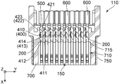
As shown in fig. 1 and 2, the connector 100 according to the present embodiment includes a connector body 110 positioned in front of the connector 100 in the front-rear direction.
As shown in fig. 2 to 5, the connector body 110 includes an opening 150, a holding member 700, a plurality of contacts 200, and a housing 750. The holding member 700 is made of an insulator. Each contact 200 is made of a conductor. The case 750 is made of metal. The case 750 partially covers the holding member 700. The front end of the housing 750 forms a fitting portion 752.
As shown in fig. 2 to 5, the opening 150 of the present embodiment opens forward in the front-rear direction of the connector body 110.
As shown in fig. 4 and 5, the holding member 700 of the present embodiment has a receiving portion 710 and a plurality of contact holding portions 720. The receiving portion 710 receives the plate portion 805 of the mating connector 800 when the connector 100 and the mating connector 800 are mated with each other. The receiving portion 710 has a rear wall 715 located rearwardly away from the opening 150 in the fore-aft direction. In detail, as understood from fig. 2, 5, and 26, when the connector 100 is mated with the mating connector 800, the fitting portion 752 is received in the mating fitting portion 842, while the plate portion 805 is received in the receiving portion 710 through the opening 150. Referring again to fig. 4 and 5, the contact holding portions 720 hold the contacts 200, respectively. Each contact holding portion 720 is a hole penetrating the holding member 700 in the front-rear direction. Each of the contact holding portions 720 has two inner walls facing each other in a width direction perpendicular to both the front-rear direction and the up-down direction. In the present embodiment, the width direction is the Y direction.
As shown in fig. 6 to 9, each contact 200 has a first support portion 300, a first contact portion 302, a second support portion 320, a second contact portion 322, a link portion 400, an upper rear narrow portion 419, an upper rear wide portion 421, a lower rear narrow portion 479, a lower rear wide portion 481, a connecting portion 500, and a fixed portion 600.
As shown in fig. 6 to 9, the first support portion 300 has an inclined portion 305, a first plate portion 307, and a protruding portion 308. The inclined portion 305 is positioned at the rear end in the front-rear direction of the first support portion 300. The inclined portion 305 is inclined forward and downward. The first plate portion 307 has a plate shape intersecting the vertical direction. The first plate portion 307 extends forward from the front end of the inclined portion 305. The boss portion 308 extends forward and upward from the front end of the first plate portion 307, and then extends forward and downward. Specifically, the front end of the boss 308 is a free end. More specifically, the convex portion 308 has a substantially semicircular shape in a plane perpendicular to the width direction. The first contact portion 302 is positioned at an upper end of the boss portion 308.
As shown in fig. 6 to 9, the first support 300 has a first edge 303 and a second edge 304 in the width direction. Each of the first edge 303 and the second edge 304 is a surface perpendicular to the width direction. The first edge 303 faces a first orientation in the width direction. The second edge 304 faces a second orientation in the width direction. In this embodiment, the first orientation is the + Y direction and the second orientation is the-Y direction. In other words, the first orientation and the second orientation are opposite to each other.
As understood from fig. 2, 3, 5, and 6, the first support 300 is elastically deformable. The first contact portion 302 is positioned near the free end of the boss 308 of the first support portion 300. The first contact portion 302 is supported by the first support portion 300. Therefore, the first contact portion 302 can move in the up-down direction. More specifically, the first contact portion 302 of the first support portion 300 of the contact 200 shown in each of fig. 6 to 10 faces upward and is movable downward in the up-down direction.
As shown in fig. 6 to 9, the first support part 300 has one dimension in the width direction and another dimension in the up-down direction, and the width direction dimension of the first support part 300 is greater than the up-down direction dimension of the first support part 300. More specifically, the first plate portion 307 of the first support portion 300 has one dimension in the width direction and another dimension in the up-down direction, and the width direction dimension of the first plate portion 307 is larger than the up-down direction dimension of the first plate portion 307.
As shown in fig. 6 to 9, the second support portion 320 has a second plate portion 327 and a folded-back portion 328. The second plate portion 327 has a plate shape intersecting the vertical direction. The folded-back portion 328 extends forward and upward from the front end of the second plate portion 327, and is then folded back to have a curved shape. The end of the turnback 328 is a free end. Specifically, the folded back portion 328 has a substantially U-shape in a plane perpendicular to the width direction. The second contact portion 322 is positioned at the upper end of the folded-back portion 328.
As shown in fig. 6 to 9, the second support portion 320 has one dimension in the width direction and another dimension in the up-down direction, and the width direction dimension of the second support portion 320 is larger than the up-down direction dimension of the second support portion 320. More specifically, the second plate portion 327 of the second support portion 320 has one dimension in the width direction and another dimension in the up-down direction, and the width direction dimension of the second plate portion 327 is larger than the up-down direction dimension of the second plate portion 327. The second plate portion 327 of the second support portion 320 is positioned below the first support portion 300 in the vertical direction.
As understood from fig. 2, 3, 5 and 6, the second support portion 320 is elastically deformable. The second contact portion 322 is positioned near the free end of the folded back portion 328 of the second support portion 320. The second contact portion 322 is supported by the second support portion 320. Accordingly, the second contact portion 322 may move in the up-down direction. More specifically, the second contact portion 322 of the second support portion 320 of the contact 200 shown in each of fig. 6 to 10 faces upward in the up-down direction and is movable downward.
As shown in fig. 6 to 9, the free end of the folded-back portion 328 of the second support portion 320 is positioned above the free end of the boss portion 308 of the first support portion 300 in the up-down direction. The free end of the boss portion 308 of the first support portion 300 is positioned rearward of the folded-back portion 328 of the second support portion 320 such that the free end of the boss portion 308 of the first support portion 300 is protected by the folded-back portion 328. Therefore, the first support 300 is prevented from being bent by an unintended force applied to the free end of the convex portion 308 of the first support 300 from the front side.
As shown in fig. 6 to 9, the coupling portion 400 couples the first and second supporting portions 300 and 320 to each other in the up-down direction. The coupling portion 400 includes an upper body portion 410, an upper curved portion 440, a lower body portion 470, a lower curved portion 460, and a wall portion 450.
As shown in fig. 6 to 9, the upper body portion 410 has a plate-like shape perpendicular to the up-down direction. The upper body portion 410 has an edge 411 facing the second orientation, and the edge 411 has a linear shape. The upper body 410 has an upper front wide portion 412, an upper front narrow portion 415, and an upper base portion 417.
As shown in fig. 6 to 9, the front end of the upper front wide portion 412 forms the front end of the upper body portion 410. The upper front wide portion 412 has a press-fit protrusion 413 protruding in a first direction in the width direction. As understood from fig. 4 and 6, the upper side front wide portion 412 is immovably fixed to the holding member 700 in the width direction. A specific method of fixing the upper front wide portion 412 to the holding member 700 will be described later. In the upper front wide portion 412, the widthwise tip of the press-fit protrusion 413 is an end portion 414 facing the first orientation.
As shown in fig. 6 to 9, the first support portion 300 extends forward from the upper side front wide portion 412 in the front-rear direction. More specifically, the inclined portion 305 of the first support portion 300 extends forward and downward from the front end of the upper front wide portion 412.
As shown in fig. 6 to 9, the upper front narrow portion 415 is positioned between the upper front wide portion 412 and the upper base portion 417 in the front-rear direction. More specifically, in the front-rear direction, the upper front narrow portion 415 is positioned rearward of the upper front wide portion 412 and forward of the upper base portion 417. The upper front narrow portion 415 is smaller in size than the upper front wide portion 412 in the width direction. Since the upper front wide portion 412 is fixed to the holding member 700 as described above, stress generated when the first supporting portion 300 is elastically deformed in the up-down direction concentrates on the first boundary portion 306 located between the first edge 303 of the first supporting portion 300 and the upper front wide portion 412 in the front-rear direction. Therefore, stress can be prevented from concentrating on the upper front narrow portion 415 having a reduced widthwise dimension.
As shown in fig. 6 and 8, the upper front narrow portion 415 has an edge 416 facing the first orientation, and the edge 416 is positioned beyond the first boundary portion 306 in the second orientation. Therefore, while the base portion of the first support portion 300 has an increased widthwise dimension, the contact 200 as a whole may have a decreased widthwise dimension.
As shown in fig. 6 to 9, the upper base portion 417 is positioned rearward of the upper front narrow portion 415 in the front-rear direction. The upper base portion 417 has a plate shape perpendicular to the vertical direction. The upper base 417 has an edge 418 facing the first orientation.
As shown in fig. 6 and 8, the upper bent portion 440 extends from the edge 418 of the upper base portion 417 of the upper body portion 410 facing the first orientation and is bent downward. Specifically, upper bend 440 extends from edge 418 of upper base 417 facing the first orientation in the first orientation while bending downward. The end portion 414 of the upper front wide portion 412 facing the first orientation, that is, the widthwise distal end of the press-fit protrusion 413, is positioned beyond the upper bent portion 440 in the first orientation. More specifically, the end 414 of the press-fit protrusion 413 of the upper side front wide portion 412 is positioned beyond the edge 442 of the upper side bent portion 440 facing the first orientation in the first orientation.
As shown in fig. 6, 7 and 9, the lower body portion 470 has a lower front wide portion 472, a lower front narrow portion 475 and a lower base portion 477.
As shown in fig. 6, 7, and 9, the lower body part 470 has a plate shape perpendicular to the up-down direction. The lower body part 470 has an edge 471 facing the second orientation, and the edge 471 has a linear shape.
As shown in fig. 6, 8, and 9, the lower front wide portion 472 has a press-fit protrusion 473 protruding in a first position in the width direction. As understood from fig. 5, the lower front wide portion 472 is immovably fixed to the holding member 700 in the width direction. A specific method of fixing the lower front wide portion 472 to the holding member 700 will be described later. In the lower front wide portion 472, the widthwise tip of the press-fit protrusion 473 is the end 474 facing the first orientation.
As shown in fig. 7, the second support portion 320 extends forward from the lower front wide portion 472 in the front-rear direction. More specifically, the second plate portion 327 of the second support portion 320 extends forward from the front end of the lower front wide portion 472.
As shown in fig. 7, the lower front narrow portion 475 is positioned between the lower front wide portion 472 and the lower base portion 477 in the front-rear direction. More specifically, in the front-rear direction, the lower front narrow portion 475 is positioned rearward of the lower front wide portion 472 and forward of the lower base portion 477. In the width direction, the dimension of the lower front narrow portion 475 is smaller than the dimension of the lower front wide portion 472. As understood from fig. 6, 7 and 9, the lower front narrow portion 475 has an edge 476 facing the first orientation, and the edge 476 is positioned in the second orientation beyond the second boundary portion 325 between the edge 324 facing the first orientation and the lower front wide portion 472 of the second support portion 320 in the front-rear direction. Therefore, while the base portion of the second support portion 320 has an increased widthwise dimension, the contact 200 as a whole may have a decreased widthwise dimension.
As shown in fig. 7, the lower base portion 477 is positioned rearward of the lower front narrowed portion 475 in the front-rear direction. The lower base 477 has a plate-like shape perpendicular to the vertical direction. As shown in fig. 6, the underside base 477 has an edge 478 facing in a first orientation.
As will be appreciated from fig. 6 and 9, the lower bend 460 extends from the edge 478 of the lower base 477 of the lower body portion 470 facing the first orientation and bends upwardly. Specifically, the underside bend 460 extends from the edge 478 of the underside base 477 facing the first orientation in the first orientation while bending upward. An end 474 of the lower front wide portion 472 facing the first orientation, i.e., a widthwise distal end of the press-fit protrusion 473 is positioned beyond the lower curved portion 460 in the first orientation. More specifically, the end 474 of the press-fit protrusion 473 of the lower front wide portion 472 is positioned beyond the edge 462 of the lower curved portion 460 facing the first orientation in the first orientation.
As shown in fig. 6, 7, 9, and 10, the wall portion 450 has a plate-like shape perpendicular to the width direction, and couples the upper bent portion 440 and the lower bent portion 460 to each other. More specifically, the wall portion 450 couples the lower end of the upper bent portion 440 and the upper end of the lower bent portion 460 to each other in the up-down direction. Although the wall portion 450 of the present embodiment is perpendicular to the width direction, the present invention is not limited thereto. The wall portion 450 may form an angle other than a right angle with the width direction as long as the wall portion 450 intersects with the width direction.
As shown in fig. 6 to 9, the upper rear narrow portion 419 is positioned between the upper base portion 417 and the upper rear wide portion 421 of the upper body portion 410 of the linking portion 400 in the front-rear direction. More specifically, in the front-rear direction, the upper rear narrow portion 419 is positioned rearward of the upper base portion 417 and forward of the upper rear wide portion 421. The upper rear narrow portion 419 has a smaller size than the upper rear wide portion 421 in the width direction.
As shown in fig. 6 to 9, the upper side rear narrow portion 419 has an edge 420 facing the first orientation, and the edge 420 is located beyond the first boundary portion 306 between the first edge 303 of the first support portion 300 and the upper side front wide portion 412 in the second orientation.
As shown in fig. 6 and 9, the upper side rear wide portion 421 is positioned rearward of the upper side rear narrow portion 419 in the front-rear direction. The upper side rear wide portion 421 has a press-fit projection 422 projecting in a first direction in the width direction. As understood from fig. 4 and 6, the upper side rear wide portion 421 is immovably fixed to the holding member 700 in the width direction. A specific method of fixing the upper rear wide portion 421 to the holding member 700 will be described later. In the upper rear wide portion 421, the widthwise end of the press-fit projection 422 is an end portion 423 facing the first orientation. The end portion 423 of the upper rear wide portion 421 facing the first orientation is positioned beyond the upper bent portion 440 in the first orientation. More specifically, the end portion 423 of the press-fit projection 422 of the upper side rear wide portion 421 is positioned beyond the edge 442 of the upper side bent portion 440 facing the first orientation in the first orientation.
As shown in fig. 6 to 9, in the contact 200 of the present embodiment, the upper main body portion 410, the upper rear narrow portion 419, and the upper rear wide portion 421 of the linking portion 400 are positioned in the same plane perpendicular to the up-down direction.
As shown in fig. 7, the lower rear narrower portion 479 is positioned between the lower base 477 and the lower rear wider portion 481 of the lower body portion 470 of the link 400 in the front-rear direction. More specifically, in the front-rear direction, the lower rear narrow portion 479 is positioned rearward of the lower base portion 477 and forward of the lower rear wide portion 481. The lower rear narrow portion 479 is smaller in size than the lower rear wide portion 481 in the width direction. The lower rear narrow portion 479 has an edge 480 facing the first orientation, and the edge 480 is positioned in the second orientation beyond a second boundary portion 325 between the edge 324 facing the first orientation and the lower front wide portion 472 of the second support portion 320.
As shown in fig. 7, the lower rear wide portion 481 is positioned rearward of the lower rear narrow portion 479 in the front-rear direction. As shown in fig. 6 and 9, the lower side rear wide portion 481 has a press-fit protrusion 482 that protrudes in a first direction in the width direction. As understood from fig. 5, the lower side rear wide portion 481 is immovably fixed to the holding member 700 in the width direction. A specific method of fixing the lower-side rear wide portion 481 to the holding member 700 will be described later. In the lower rear wide portion 481, the widthwise distal end of the press-fit projection 482 is an end portion 483 facing the first orientation. An end portion 483 of the lower side rear wide portion 481 facing the first direction is positioned beyond the lower side bent portion 460 in the first direction. More specifically, as shown in fig. 6, the end portion 483 of the press-fit projection 482 of the lower side rear wide portion 481 is positioned beyond the edge 462 of the lower side bent portion 460 facing the first orientation in the first orientation.
As shown in fig. 7, in the contact 200 of the present embodiment, the lower main body portion 470, the lower rear narrow portion 479, and the lower rear wide portion 481 of the link portion 400 are positioned in the same plane perpendicular to the up-down direction.
As shown in fig. 6 to 10, the connecting portion 500 extends rearward and downward from the rear end of the lower side rear wide portion 481. The rear end of the connecting portion 500 is connected to the front end of the fixed portion 600. The fixed part 600 is connected to a cable (not shown) in use.
As shown in fig. 2 to 5, the plurality of contacts 200 are held by the holding member 700 so as to be arranged in two rows. The contacts 200 of each row are arranged in the width direction. The two rows are arranged in the up-down direction and include an upper row and a lower row located below the upper row. The upper row of contacts 200 corresponds to mating upper side contacts 810, respectively. The lower row of contacts 200 corresponds to mating underside contacts 820, respectively. More specifically, each of the contacts 200 of the present embodiment is inserted forward from the rear end of the holding member 700 to be press-fitted into the corresponding contact holding portion 720. As understood from fig. 5, each of the contacts 200 of the upper row is turned upside down and press-fitted into the corresponding contact holding portion 720. Meanwhile, each of the press- fit protrusions 413, 422, 473, 482 of the contact 200 bites into one of the inner walls of the corresponding contact holding portion 720 that face each other in the width direction. Also, at the same time, the edge 411 of the upper body portion 410 of the contact 200 contacts the remaining one of the inner walls of the corresponding contact holding portion 720 that face each other in the width direction. Since the edge 411 of the upper main body portion 410 has a straight line shape as described above, each of the contacts 200 can be properly aligned in the corresponding contact holding portion 720. Further, at the same time, the bottom surface of the second support portion 320 of the contact 200 does not contact the holding member 700.
As understood from fig. 2 to 5 and 26, when the connector body 110 of the connector 100 of the present embodiment is mated with the mating connector 800, the first contact portion 302 of the first support portion 300 and the second contact portion 322 of the second support portion 320 of each contact 200 of the upper row of the connector body 110 are brought into contact with the corresponding mating upper-side contact 810 of the mating connector 800, while the first contact portion 302 of the first support portion 300 and the second contact portion 322 of the second support portion 320 of each contact 200 of the lower row of the connector body 110 are brought into contact with the corresponding mating lower-side contact 820 of the mating connector 800. Meanwhile, the free end of the boss portion 308 of the first support portion 300 and the free end of the turnback portion 328 of the second support portion 320 do not contact each other. Specifically, when the connector 100 and the mating connector 800 are mated with each other, both the first contact portion 302 and the second contact portion 322 of each contact 200 in the upper row are simultaneously brought into contact with the corresponding mating upper-side contact 810, while both the first contact portion 302 and the second contact portion 322 of each contact 200 in the lower row are simultaneously brought into contact with the corresponding mating lower-side contact 820. Therefore, when the connector 100 and the mating connector 800 are mated with each other, each contact 200 of the upper row is firmly and stably contacted with the corresponding mating upper-side contact 810, while each contact 200 of the lower row is firmly and stably contacted with the corresponding mating lower-side contact 820.
The structure of the contact 200 is not limited thereto. For example, the contact 200 may be deformed as described below.
Referring to fig. 11 to 14, each of the contacts 200A and 200B according to the modification of the first embodiment has substantially the same structure as the contact 200 (see fig. 8) according to the first embodiment described above. Therefore, the same reference numerals as those of the contact 200 of the first embodiment are used to denote the same components as those of the contact 200 of the first embodiment in the contacts 200A, 200B shown in fig. 11 to 14.
As shown in fig. 11 and 12, unlike the contact 200 of the first embodiment, the contact 200A according to the modification has press- fit protrusions 413, 430, 422, 435, 473, 484, 482, and 485. The press- fit protrusions 413 and 430 protrude outward from both widthwise ends of the upper-side front wide portion 412, respectively. The press- fit protrusions 422 and 435 protrude outward from both widthwise ends of the upper-side rear wide portion 421, respectively. The press- fit protrusions 473 and 484 protrude outward from both widthwise ends of the lower front wide portion 472, respectively. The press- fit projections 482 and 485 protrude outward from both widthwise ends of the lower-side rear wide portion 481, respectively. Therefore, the contact 200A is firmly held by the holding member 700.
As shown in fig. 13 and 14, unlike the contact 200 of the first embodiment, a contact 200B of another modification has press- fit protrusions 430, 435, 484, and 485. The press-fit protrusion 430 protrudes from the upper front wide portion 412 in the second orientation. The press-fit projection 435 projects from the upper side rear wide portion 421 in the second orientation. The press-fit projection 484 protrudes from the lower front wide portion 472 in the second orientation. The press-fit projection 485 protrudes from the lower rear wide portion 481 in the second orientation. Since the upper front wide portion 412 is also firmly fixed to the holding member 700 in the present modification, stress generated when the first supporting portion 300 is elastically deformed in the up-down direction is concentrated on the boundary portion between the second edge 304 of the first supporting portion 300 and the upper front wide portion 412. Therefore, stress can be prevented from concentrating on the upper front narrow portion 415 having a reduced widthwise dimension. In the present modification, the end portion 414B of the upper front wide portion 412 facing the first direction is positioned beyond the upper bent portion 440 in the first direction, and the end portion 423B of the upper rear wide portion 421 facing the first direction is positioned beyond the upper bent portion 440 in the first direction. Similarly, each of an end (not shown) of the lower side front wide portion 472 facing the first orientation and an end (not shown) of the lower side rear wide portion 481 facing the first orientation is positioned beyond the lower side bent portion 460 in the first orientation.
(second embodiment)
Referring to fig. 1, 2, and 15, a connector (not shown) according to a second embodiment of the present invention includes a connector body 110C instead of the connector body 110 (see fig. 2) in the connector 100 (see fig. 1) of the first embodiment. The connector body 110C according to the present embodiment has substantially the same structure as the connector body 110 (see fig. 2) according to the first embodiment described above. Therefore, the same reference numerals as those of the connector body 110 of the first embodiment are used to denote the same components as those of the connector body 110 of the first embodiment in the connector body 110C shown in fig. 15 to 18. For the direction in the present embodiment, the same expression as in the first embodiment will be used below.
As shown in fig. 15 to 18, the connector body 110C has an opening 150, a holding member 700C, a plurality of contacts 200C, and a housing 750.
As shown in fig. 15 to 18, the holding member 700C of the present embodiment has a receiving portion 710 and a plurality of contact holding portions 720C. When the connector (not shown) of the present embodiment and the mating connector 800 are mated with each other, the receiving portion 710 receives the plate portion 805 of the mating connector 800. The receiving portion 710 has a rear wall 715C positioned rearwardly in the fore-aft direction away from the opening 150. The contact holding portions 720C hold the contacts 200C, respectively. Each contact holding portion 720C is a hole that penetrates the holding member 700C in the front-rear direction. Each of the contact holding portions 720C has two inner walls facing each other in the width direction.
As shown in fig. 19 to 23, each contact 200C has a first support portion 300C, a second support portion 320C, a first contact portion 302C, a second contact portion 322C, a linking portion 400C, an upper rear wide portion 421C, an upper rear narrow portion 419C, a connecting portion 500C, and a fixed portion 600C.
As shown in fig. 19 to 23, the first support portion 300C has an inclined portion 305C, a first plate portion 307C, and a protruding portion 308C. The inclined portion 305C is positioned at the rear end in the front-rear direction of the first support portion 300C. The inclined portion 305C is inclined forward and downward. The first plate portion 307C has a plate shape intersecting the vertical direction. The first plate portion 307C extends forward and upward from the front end of the inclined portion 305C. The boss portion 308C extends forward and upward from the front end of the first plate portion 307C, and then extends forward and downward. Specifically, the front end of the boss 308C is a free end. More specifically, the convex portion 308C has a substantially semicircular shape in a plane perpendicular to the width direction. The first contact portion 302C is positioned at the upper end of the boss portion 308C.
As shown in fig. 19 to 22, the first support portion 300C has a first edge 303C and a second edge 304C in the width direction. The first edge 303C faces a first orientation in the width direction, and the second edge 304C faces a second orientation in the width direction. In this embodiment, the first orientation is the-Y direction and the second orientation is the + Y direction. In other words, the first orientation and the second orientation are opposite to each other.
As understood from fig. 16, 18, and 19, the first support portion 300C is elastically deformable. The first contact portion 302C is positioned near the free end of the boss 308C of the first support portion 300C. The first contact portion 302C is supported by the first support portion 300C. Therefore, the first contact portion 302C is movable in the up-down direction perpendicular to the front-rear direction. More specifically, the first contact portion 302C of the first support portion 300C of the contact 200C shown in each of fig. 19 to 23 faces upward and is movable downward in the up-down direction.
As shown in fig. 19 to 23, the first support part 300C has one dimension in the width direction and another dimension in the up-down direction, and the width direction dimension of the first support part 300C is larger than the up-down direction dimension of the first support part 300C. More specifically, the first plate portion 307C of the first support portion 300C has one dimension in the width direction and another dimension in the up-down direction, and the width direction dimension of the first plate portion 307C is larger than the up-down direction dimension of the first plate portion 307C.
As shown in fig. 19, 20, and 22, the second support portion 320C has a second plate portion 327C and a folded-back portion 328C. The second plate portion 327C has a plate shape perpendicular to the width direction. The folded-back portion 328C extends rearward and upward from the front end of the second plate portion 327C. The folded back portion 328C has a rear edge 329C that intersects both the front-rear direction and the up-down direction. Specifically, the second support portion 320C has a half-arrow shape when viewed in the width direction. The second contact portion 322C is positioned at the upper end of the folded back portion 328C.
As shown in fig. 19 to 23, the second support portion 320C has one dimension in the width direction and another dimension in the up-down direction, and the width direction dimension of the second support portion 320C is smaller than the up-down direction dimension of the second support portion 320C. More specifically, the second plate portion 327C of the second support portion 320C has one dimension in the width direction and another dimension in the up-down direction, and the width direction dimension of the second plate portion 327C is smaller than the up-down direction dimension of the second plate portion 327C. The second plate portion 327C of the second support portion 320C is positioned below the first support portion 300C in the vertical direction.
As understood from fig. 16, 18, and 19, the second support portion 320C is elastically deformable. In addition, the second contact portion 322C is supported by the second support portion 320C. Therefore, the second contact portion 322C may move in the up-down direction. More specifically, the second contact portion 322C of the second support portion 320C of the contact 200C shown in fig. 19 to 23 faces upward in the up-down direction and is movable downward.
As shown in fig. 19 to 22, the upper end of the rear edge 329C of the folded-back portion 328C of the second support portion 320C is positioned above the free end of the boss portion 308C of the first support portion 300C in the up-down direction. The free end of the raised portion 308C of the first support 300C is positioned behind the trailing edge 329C of the folded back portion 328C of the second support 320C such that the free end of the raised portion 308C of the first support 300C is protected by the trailing edge 329C. Therefore, the first support part 300C is prevented from being bent by an unintended force applied to the free end of the convex portion 308C of the first support part 300C from the front side.
As shown in fig. 19, 20, and 22, the coupling portion 400C couples the first support portion 300C and the second support portion 320C to each other in the up-down direction. The coupling portion 400C has an upper body portion 410C, an upper bent portion 440C, a wall portion 450C, and a bent portion 465.
As shown in fig. 19 to 22, the upper body portion 410C has an upper front wide portion 412C, an upper front narrow portion 415C, and an upper base portion 417C.
As shown in fig. 19 to 22, the upper body portion 410C has a plate-like shape. The upper body portion 410C has an edge 411C facing the second orientation, and the edge 411C has a linear shape.
As shown in fig. 19 to 21, the upper side front wide portion 412C has a press-fit protrusion 413C protruding in a first position in the width direction. As shown in fig. 17, the upper front wide portion 412C is immovably fixed to the holding member 700C in the width direction. A specific method of fixing the upper front wide portion 412C to the holding member 700C will be described later. In the upper front wide portion 412C, the widthwise tip of the press-fit protrusion 413C is an end portion 414C facing the first orientation.
As shown in fig. 19 to 22, the first support portion 300C extends forward from the upper side front wide portion 412C in the front-rear direction. More specifically, the inclined portion 305C of the first support portion 300C extends forward and downward from the front end of the upper front wide portion 412C.
As shown in fig. 19 to 22, the upper front narrow portion 415C is positioned between the upper front wide portion 412C and the upper base portion 417C in the front-rear direction. More specifically, in the front-rear direction, the upper front narrow portion 415C is positioned rearward of the upper front wide portion 412C and forward of the upper base portion 417C. The upper front narrow portion 415C is smaller in size than the upper front wide portion 412C in the width direction. Since the upper front wide portion 412C is fixed to the holding member 700C as described above, stress generated when the first supporting portion 300C is elastically deformed in the up-down direction concentrates on the first boundary portion 306C between the first edge 303C of the first supporting portion 300C and the upper front wide portion 412C in the front-rear direction. Therefore, stress can be prevented from concentrating on the upper front narrow portion 415C having a reduced widthwise dimension.
As shown in fig. 21, the upper front narrow portion 415C has an edge 416C facing the first orientation, and the edge 416C is located beyond the first boundary portion 306C in the second orientation. Therefore, while the base portion of the first support portion 300C has an increased widthwise dimension, the contact 200C as a whole may have a decreased widthwise dimension.
As shown in fig. 19 to 22, the upper base portion 417C is positioned rearward of the upper front narrow portion 415C in the front-rear direction. The upper base 417C has a plate shape perpendicular to the vertical direction. The upper base 417C has an edge 418C facing the first orientation. The edge 418C of the present embodiment intersects both the front-rear direction and the width direction.
As shown in fig. 19-21, the upper bend 440C extends from an edge 418C of the upper base 417C facing the first orientation and bends downward. Specifically, the upper bent portion 440C extends in the first orientation and rearward from the edge 418C of the upper base portion 417C facing the first orientation while being bent downward. An end portion 414C of the upper front wide portion 412C facing the first orientation, that is, a widthwise distal end of the press-fit protrusion 413C, is positioned beyond the upper bent portion 440C in the first orientation. More specifically, the end 414C of the press-fit protrusion 413C of the upper side front wide portion 412C is positioned beyond the edge 442C of the upper side bent portion 440C facing the first orientation in the first orientation.
As shown in fig. 19 and 20, the wall portion 450C has a plate-like shape intersecting both the front-rear direction and the width direction, and extends downward from the lower end of the upper bent portion 440C.
As shown in fig. 19 to 22, the curved portion 465 extends forward from a lower portion of the front end of the wall portion 450C and in the second orientation. The second support portion 320C extends forward from the front end of the curved portion 465.
As shown in fig. 19 to 22, the upper rear narrow portion 419C is positioned between the upper base portion 417C and the upper rear wide portion 421C of the upper body portion 410C of the linking portion 400C in the front-rear direction. More specifically, in the front-rear direction, the upper side rear narrow portion 419C is positioned rearward of the upper side base portion 417C and forward of the upper side rear wide portion 421C. The upper rear narrow portion 419C is smaller in size than the upper rear wide portion 421C in the width direction.
As shown in fig. 21, the upper side rear narrow portion 419C has an edge 420C facing the first orientation, and the edge 420C is located beyond the first boundary portion 306C between the first edge 303C of the first support portion 300C and the upper side front wide portion 412C in the second orientation.
As shown in fig. 19 to 22, the upper side rear wide portion 421C is positioned rearward of the upper side rear narrow portion 419C in the front-rear direction. The upper side rear wide portion 421C has a press-fit projection 422C projecting in a first direction in the width direction. As shown in fig. 17, the upper side rear wide portion 421C is immovably fixed to the holding member 700C in the width direction. A specific method of fixing the upper rear wide portion 421C to the holding member 700C will be described later. In the upper rear wide portion 421C, the widthwise end of the press-fit projection 422C is an end portion 423C facing the first orientation. The end 423C of the upper rear wide portion 421C facing the first direction is positioned beyond the upper bent portion 440C in the first direction. More specifically, the end portion 423C of the press-fit projection 422C of the upper side rear wide portion 421C is positioned beyond the edge 442C of the upper side bent portion 440C facing the first orientation in the first orientation.
As shown in fig. 19 to 22, in the contact 200C of the present embodiment, the upper main body portion 410C, the upper rear narrow portion 419C, and the upper rear wide portion 421C of the linking portion 400C are positioned in the same plane perpendicular to the up-down direction.
As shown in fig. 19 to 22, the connecting portion 500C extends rearward and downward from the rear end of the upper side rear wide portion 421C. The rear end of the connecting portion 500C is connected to the front end of the fixed portion 600C. The fixed portion 600C is connected to a cable (not shown) in use.
As shown in fig. 16 to 18, the plurality of contacts 200C are held by the holding member 700C so as to be arranged in two rows. The contacts 200C of each row are arranged in the width direction. The two rows are arranged in the up-down direction and include an upper row and a lower row located below the upper row. The upper row of contacts 200C corresponds to the mating upper side contacts 810, respectively. The lower row of contacts 200C correspond to mating lower side contacts 820, respectively. More specifically, each of the contacts 200C of the present embodiment is inserted forward from the rear end of the holding member 700C to be press-fitted into the corresponding contact holding portion 720C. As understood from fig. 18, each of the upper row of contacts 200C is turned upside down and press-fitted into the corresponding contact holding portion 720C. Meanwhile, each of the press- fit protrusions 413C and 422C of the contact 200C bites into one of the inner walls of the corresponding contact holding portion 720C that face each other in the width direction. Also at the same time, the edge 411C of the upper body portion 410C of the contact 200C contacts the remaining one of the inner walls of the corresponding contact holding portion 720C that face each other in the width direction. Since the edge 411C of the upper side main body portion 410C has a straight line shape as described above, each of the contacts 200C can be appropriately aligned in the corresponding contact holding portion 720C.
As shown in fig. 15 to 18 and 26, when the connector body 110C of the connector 100C of the present embodiment is mated with the mating connector 800, the first contact portion 302C of the first support portion 300C and the second contact portion 322C of the second support portion 320C of each contact 200C of the upper row of the connector body 110C are brought into contact with the corresponding mating upper-side contact 810 of the mating connector 800, while the first contact portion 302C of the first support portion 300C and the second contact portion 322C of the second support portion 320C of each contact 200C of the lower row of the connector body 110C are brought into contact with the corresponding mating lower-side contact 820 of the mating connector 800. Meanwhile, the free end of the convex portion 308C of the first support portion 300C and the rear edge 329C of the folded-back portion 328C of the second support portion 320C do not contact each other. Specifically, when the connector 100C and the mating connector 800 are mated with each other, both the first contact portion 302C and the second contact portion 322C of each contact 200C in the upper row are simultaneously brought into contact with the corresponding mating upper-side contact 810, while both the first contact portion 302C and the second contact portion 322C of each contact 200C in the lower row are simultaneously brought into contact with the corresponding mating lower-side contact 820. Therefore, when the connector 100C and the mating connector 800 are mated with each other, each contact 200C of the upper row is firmly and stably contacted with the corresponding mating upper-side contact 810, while each contact 200C of the lower row is firmly and stably contacted with the corresponding mating lower-side contact 820.
The structure of the contact 200C is not limited thereto. For example, the contact 200C may be deformed as described below.
Referring to fig. 24 and 25, each of the contacts 200D and 200E according to the modification of the second embodiment of the present invention has substantially the same structure as the contact 200C (see fig. 21) according to the second embodiment described above. Therefore, the same reference numerals as those of the contact 200C of the second embodiment are used to denote the same components as those of the contact 200C of the second embodiment in the contacts 200D, 200E shown in fig. 24 and 25.
As shown in fig. 24, unlike the contact 200C of the second embodiment, the contact 200D according to the modification has press- fit protrusions 413C, 430D, 422C, and 435D. The press- fit protrusions 413C and 430D protrude outward from both widthwise ends of the upper-side front wide portion 412C, respectively. The press- fit protrusions 422C and 435D protrude outward from both widthwise ends of the upper-side rear wide portion 421C, respectively. Therefore, the contact 200D is firmly held by the holding member 700C.
As shown in fig. 25, unlike the contact 200C of the second embodiment, a contact 200E of another modification has press- fit protrusions 430E and 435E. The press-fit protrusion 430E protrudes from the upper front wide portion 412C in the second orientation. The press-fit projection 435E projects from the upper side rear wide portion 421C in the second orientation. Since the upper front wide portion 412C is also firmly fixed to the holding member 700C in the present modification, stress generated when the first supporting portion 300C is elastically deformed in the up-down direction is concentrated on the boundary portion between the second edge 304C of the first supporting portion 300C and the upper front wide portion 412C. Therefore, stress can be prevented from concentrating on the upper front narrow portion 415C having a reduced widthwise dimension. In the present modification, the end portion 414E of the upper front wide portion 412C facing the first direction is positioned beyond the upper bent portion 440C in the first direction, and the end portion 423E of the upper rear wide portion 421C facing the first direction is positioned beyond the upper bent portion 440C in the first direction.
Although the present invention has been specifically described above with reference to a plurality of embodiments, the present invention is not limited thereto but is susceptible to various modifications and alternative forms.
Although the connector bodies 110, 110C of the above-described embodiments include the plurality of contacts 200, 200C, the present invention is not limited thereto. The number of the contacts 200, 200C of the connector body 110, 110C may be one. In other words, the connector body 110, 110C may include at least one contact 200, 200C.
In the contacts 200, 200A, 200B, 200C, 200D, 200E of the above-described embodiments, although the press-fit protrusions are also provided on the portions other than the upper front wide portions 412, 412C, the present invention is not limited thereto. The press-fit protrusions may be provided only on the upper front wide portions 412, 412C.
In particular, in the contacts 200, 200A, 200B of the present embodiment, the lower front wide portion 472 is fixed to the holding member 700, and the bottom surface of the second support portion 320 is not in contact with the holding member 700. However, the lower front wide portion 472 may not be fixed to the holding member 700 as long as the bottom surface of the second support portion 320 is in contact with the holding member 700 and received by the holding member 700.
Although the upper front wide portions 412, 412C of the contacts 200, 200A, 200B, 200C, 200D, 200E of the present embodiment are fixed to the holding members 700, 700C by press-fitting, the present invention is not limited thereto. The upper front wide portions 412, 412C may be fixed to the holding members 700, 700C so as to be immovable in the width direction. For example, the upper front wide portions 412, 412C may be fixed by insert molding.
In the contacts 200, 200A, 200B, 200C, 200D, 200E of the present embodiment, the upper main body portions 410, 410C, the upper rear narrow portions 419, 419C, and the upper rear wide portions 421, 421C are positioned in the same plane perpendicular to the up-down direction. However, the upper body portions 410, 410C, the upper rear narrow portions 419, 419C, and the upper rear wide portions 421, 421C may not be positioned in the same plane perpendicular to the up-down direction. Specifically, there may be a step between the upper main body portion 410, 410C and the upper rear narrow portion 419, 419C, and a step between the upper rear narrow portion 419, 419C and the upper rear wide portion 421, 421C.
In the contacts 200, 200A, 200B of the present embodiment, the lower main body portion 470, the lower rear narrow portion 479, and the lower rear wide portion 481 are positioned in the same plane perpendicular to the up-down direction. However, the lower main body portion 470, the lower rear narrow portion 479, and the lower rear wide portion 481 may not necessarily be located in the same plane perpendicular to the up-down direction. Specifically, there may be a step between the lower side body portion 470 and the lower side rear narrow portion 479, and a step between the lower side rear narrow portion 479 and the lower side rear wide portion 481.
While there has been described what are believed to be the preferred embodiments of the invention, those skilled in the art will recognize that other and further modifications may be made thereto without departing from the spirit of the invention, and it is intended to claim all such embodiments as fall within the true scope of the invention.
Claims (5)
1. A connector capable of mating with a mating connector in a front-to-rear direction, wherein:
the connector comprises at least one contact and a retention member;
the holding member holds the at least one contact;
the at least one contact member has a first support portion, a second support portion, a first contact portion, a second contact portion, and a coupling portion;
each of the first and second supporting portions being elastically deformable;
the first contact portion is supported by the first support portion;
the second contact portion is supported by the second support portion;
each of the first contact portion and the second contact portion is movable in an up-down direction perpendicular to the front-rear direction and faces upward;
the first support portion has a first edge and a second edge in a width direction perpendicular to both the front-rear direction and the up-down direction;
the first edge faces a first orientation in the width direction;
the second edge faces a second orientation in the width direction;
the first orientation and the second orientation are opposite to each other in the width direction;
the coupling portion couples the first support portion and the second support portion to each other;
the connecting part is provided with an upper main body part and an upper bending part;
the upper body part has an upper front wide part, an upper front narrow part and an upper base;
the upper side front wide portion is immovably fixed to the holding member in the width direction;
the first support portion extends forward in the front-rear direction from the upper side front wide portion;
the upper front narrow portion is positioned between the upper front wide portion and the upper base portion in the front-rear direction;
the upper front narrow portion has an edge facing the first orientation;
the at least one contact has a first boundary portion between a first edge of the first support portion and the upper side front wide portion in the front-rear direction;
an edge of the upper front narrow portion is positioned beyond the first border portion in the second orientation;
the upper base has an edge facing the first orientation;
the upper side bent portion extends from an edge of the upper side base portion and is bent downward;
the second support portion is located below the first support portion in the up-down direction;
the second support portion has one dimension in the width direction and another dimension in the up-down direction; and is
The dimension of the second support portion in the width direction is smaller than the dimension of the second support portion in the vertical direction.
2. The connector of claim 1, wherein:
the first support portion has one dimension in the width direction and another dimension in the up-down direction;
the dimension of the first support portion in the width direction is larger than the dimension of the first support portion in the vertical direction;
the upper main body portion has a flat plate shape;
a press-fit projection projecting in the width direction is provided at an upper front wide portion of the upper body;
the upper front wide portion has an end portion facing the first direction; and is
An end portion of the upper front wide portion is positioned beyond the upper bent portion in the first direction.
3. The connector of claim 1, wherein:
the at least one contact further having an upper rear wide portion and an upper rear narrow portion;
the upper side rear wide portion is positioned rearward of the upper side rear narrow portion in the front-rear direction;
the upper side rear wide portion is immovably fixed to the holding member in the width direction;
the upper side rear wide portion is positioned between the upper side base portion and the upper side rear wide portion in the front-rear direction; and is
The upper rear narrow portion has a dimension smaller than a dimension of the upper rear wide portion in the width direction.
4. The connector of claim 3, wherein:
the upper rear wide portion has an end portion facing the first orientation; and is
An end portion of the upper side rear wide portion is positioned beyond the upper side bent portion in the first direction.
5. The connector of claim 1, wherein:
the upper body portion has an edge facing the second orientation; and is
The edge of the upper body portion has a linear shape.
Applications Claiming Priority (3)
| Application Number | Priority Date | Filing Date | Title |
|---|---|---|---|
| JP2016197129A JP6776085B2 (en) | 2016-10-05 | 2016-10-05 | connector |
| JP2016-197129 | 2016-10-05 | ||
| CN201710728964.1A CN107919562B (en) | 2016-10-05 | 2017-08-23 | Connector with a locking member |
Related Parent Applications (1)
| Application Number | Title | Priority Date | Filing Date |
|---|---|---|---|
| CN201710728964.1A Division CN107919562B (en) | 2016-10-05 | 2017-08-23 | Connector with a locking member |
Publications (2)
| Publication Number | Publication Date |
|---|---|
| CN110492287A CN110492287A (en) | 2019-11-22 |
| CN110492287B true CN110492287B (en) | 2021-08-24 |
Family
ID=61758509
Family Applications (2)
| Application Number | Title | Priority Date | Filing Date |
|---|---|---|---|
| CN201710728964.1A Active CN107919562B (en) | 2016-10-05 | 2017-08-23 | Connector with a locking member |
| CN201910899488.9A Active CN110492287B (en) | 2016-10-05 | 2017-08-23 | Connector with a locking member |
Family Applications Before (1)
| Application Number | Title | Priority Date | Filing Date |
|---|---|---|---|
| CN201710728964.1A Active CN107919562B (en) | 2016-10-05 | 2017-08-23 | Connector with a locking member |
Country Status (3)
| Country | Link |
|---|---|
| US (2) | US10553997B2 (en) |
| JP (1) | JP6776085B2 (en) |
| CN (2) | CN107919562B (en) |
Families Citing this family (6)
| Publication number | Priority date | Publication date | Assignee | Title |
|---|---|---|---|---|
| US11050179B2 (en) * | 2018-05-11 | 2021-06-29 | Foxconn (Kunshan) Computer Connector Co., Ltd. | Electrical connector having a contact formed of first and second contact parts coupled together |
| JP6605660B1 (en) | 2018-06-19 | 2019-11-13 | 日本航空電子工業株式会社 | Connector device, connector and mating connector |
| CN109326909A (en) * | 2018-11-20 | 2019-02-12 | 安费诺商用电子产品(成都)有限公司 | A kind of high-power card class connection terminal of high density and connector |
| US11196198B2 (en) * | 2019-05-03 | 2021-12-07 | Foxconn (Kunshan) Computer Connector Co., Ltd. | Card edge connector with improved contacts |
| CN114243391B (en) * | 2020-09-08 | 2024-04-02 | 台达电子工业股份有限公司 | Power supply device and conductive spring piece thereof |
| US11367979B1 (en) * | 2020-12-28 | 2022-06-21 | Industrial Technology Research Institute | Terminal components of connector and connector structure |
Citations (5)
| Publication number | Priority date | Publication date | Assignee | Title |
|---|---|---|---|---|
| CN1048124A (en) * | 1989-06-09 | 1990-12-26 | 纳幕尔杜邦公司 | Contact member for insulation shift |
| JPH07106012A (en) * | 1993-10-07 | 1995-04-21 | Nec Corp | Connector |
| CN104425936A (en) * | 2013-09-05 | 2015-03-18 | 意力速电子工业株式会社 | Connector |
| CN104769783A (en) * | 2012-10-29 | 2015-07-08 | 罗森伯格高频技术有限及两合公司 | Contact element for transmitting high-frequency signals between two circuit boards |
| CN105375145A (en) * | 2014-08-06 | 2016-03-02 | 第一电子工业株式会社 | Contactor and connector having the same |
Family Cites Families (21)
| Publication number | Priority date | Publication date | Assignee | Title |
|---|---|---|---|---|
| JPH0313984Y2 (en) * | 1986-10-14 | 1991-03-28 | ||
| JPH0334852Y2 (en) * | 1986-12-26 | 1991-07-24 | ||
| US5286215A (en) * | 1992-10-15 | 1994-02-15 | Adc Telecommunications, Inc. | Make-before-break PC board edge connector |
| US5605464A (en) * | 1994-03-22 | 1997-02-25 | Molex Incorporated | IC package connector |
| US5551897A (en) * | 1995-02-08 | 1996-09-03 | Osram Sylvania Inc. | Electrical contact |
| US5634819A (en) * | 1996-01-16 | 1997-06-03 | Hon Hai Precision Ind. Co., Ltd. | Electrical connector |
| JP3117439B1 (en) * | 1999-07-06 | 2000-12-11 | 山一電機株式会社 | Pinching socket |
| JP4181307B2 (en) * | 2001-01-19 | 2008-11-12 | 山一電機株式会社 | Card connector |
| US6634911B1 (en) * | 2002-06-07 | 2003-10-21 | Hon Hai Precision Ind. Co., Ltd. | Contact for electrical connector |
| US6821163B2 (en) * | 2003-02-25 | 2004-11-23 | Hon Hai Precision Ind. Co., Ltd. | Electrical connector having terminals with reliable retention protrusions |
| JP5001193B2 (en) | 2008-02-19 | 2012-08-15 | 富士通コンポーネント株式会社 | Connector device |
| JP5288851B2 (en) | 2008-03-21 | 2013-09-11 | 第一電子工業株式会社 | connector |
| CN201478526U (en) * | 2009-06-30 | 2010-05-19 | 富士康(昆山)电脑接插件有限公司 | Electrical connector |
| US7988500B2 (en) * | 2009-12-16 | 2011-08-02 | Sensata Technologies Massachusetts, Inc. | Socket and contact having anchors |
| JP2012221592A (en) * | 2011-04-04 | 2012-11-12 | Fujitsu Component Ltd | Connector |
| US9065225B2 (en) * | 2012-04-26 | 2015-06-23 | Apple Inc. | Edge connector having a high-density of contacts |
| CN104584331B (en) * | 2012-09-05 | 2017-02-22 | 意力速电子工业株式会社 | Connector |
| JP6388472B2 (en) * | 2013-12-09 | 2018-09-12 | 富士通コンポーネント株式会社 | Contacts and connectors |
| CN203707414U (en) * | 2013-12-18 | 2014-07-09 | 深圳市得润电子股份有限公司 | Electric connector and conductive terminal thereof |
| JP6006356B2 (en) * | 2014-08-06 | 2016-10-12 | 第一電子工業株式会社 | Contact and connector using the contact |
| CN106785543B (en) * | 2016-08-19 | 2019-07-26 | 富士康(昆山)电脑接插件有限公司 | Bayonet connector |
-
2016
- 2016-10-05 JP JP2016197129A patent/JP6776085B2/en active Active
-
2017
- 2017-08-23 CN CN201710728964.1A patent/CN107919562B/en active Active
- 2017-08-23 CN CN201910899488.9A patent/CN110492287B/en active Active
- 2017-09-05 US US15/696,029 patent/US10553997B2/en active Active
-
2019
- 2019-09-06 US US16/563,393 patent/US10714882B2/en active Active
Patent Citations (5)
| Publication number | Priority date | Publication date | Assignee | Title |
|---|---|---|---|---|
| CN1048124A (en) * | 1989-06-09 | 1990-12-26 | 纳幕尔杜邦公司 | Contact member for insulation shift |
| JPH07106012A (en) * | 1993-10-07 | 1995-04-21 | Nec Corp | Connector |
| CN104769783A (en) * | 2012-10-29 | 2015-07-08 | 罗森伯格高频技术有限及两合公司 | Contact element for transmitting high-frequency signals between two circuit boards |
| CN104425936A (en) * | 2013-09-05 | 2015-03-18 | 意力速电子工业株式会社 | Connector |
| CN105375145A (en) * | 2014-08-06 | 2016-03-02 | 第一电子工业株式会社 | Contactor and connector having the same |
Also Published As
| Publication number | Publication date |
|---|---|
| CN110492287A (en) | 2019-11-22 |
| US20190393657A1 (en) | 2019-12-26 |
| US20180097320A1 (en) | 2018-04-05 |
| CN107919562A (en) | 2018-04-17 |
| US10553997B2 (en) | 2020-02-04 |
| JP6776085B2 (en) | 2020-10-28 |
| CN107919562B (en) | 2020-06-09 |
| US10714882B2 (en) | 2020-07-14 |
| JP2018060668A (en) | 2018-04-12 |
Similar Documents
| Publication | Publication Date | Title |
|---|---|---|
| CN110492287B (en) | Connector with a locking member | |
| JP4374074B1 (en) | Electrical connection terminal and connector using the same | |
| US4685886A (en) | Electrical plug header | |
| US10566735B2 (en) | Connector | |
| US6520811B2 (en) | Terminal fitting | |
| US4415221A (en) | Female type electrical connector | |
| US8371883B2 (en) | Connector assembly | |
| CN112290254B (en) | Connector assembly | |
| KR20150009993A (en) | Connector between cable and substrate | |
| EP0902504A2 (en) | Front holder-incorporating connector | |
| CN108574164B (en) | Electric connector and electric connector assembly | |
| US20190296467A1 (en) | Board connector | |
| US6196884B1 (en) | Female metal terminal that stably connects with male metal terminal | |
| US20180076576A1 (en) | Connector | |
| US20230130951A1 (en) | Terminal fitting and connector | |
| EP4068523B1 (en) | Connector | |
| CN111355096B (en) | Split connector | |
| US10403998B2 (en) | Female terminal and connector | |
| US20230069874A1 (en) | Male terminal fitting and terminal structure | |
| US11646521B2 (en) | Connector with terminal fitting | |
| US20230352869A1 (en) | Connector | |
| KR20220019482A (en) | Connector and connector assembly | |
| JP4425965B2 (en) | connector | |
| CN116780232A (en) | Connector with a plurality of connectors |
Legal Events
| Date | Code | Title | Description |
|---|---|---|---|
| PB01 | Publication | ||
| PB01 | Publication | ||
| SE01 | Entry into force of request for substantive examination | ||
| SE01 | Entry into force of request for substantive examination | ||
| GR01 | Patent grant | ||
| GR01 | Patent grant |