Method for semi-permanent mold casting process
Introduction to the design reside in
The present disclosure relates to molding of metal cast parts, including automotive vehicle engine parts.
Parts, such as cylinder heads for automotive vehicle engines, are typically cast using semi-permanent molds that are filled with a molten metal, such as aluminum, and gravity fed into the mold.
Semi-permanent molds (SPMs) involve casting processes that produce aluminum alloy castings from reusable metal molds and sand cores to form internal passages within the resulting casting. The SPM cylinder head mold is comprised of a plurality of horizontal side sliding mold parts (3 or 4) that are positioned above a base mold part. SPMs are typically arranged in two halves, with a sand core being placed in place prior to bringing the two mold halves together.
After the molten metal is poured, the material cools and shrinks within the mold, with shrinkage as high as about 7% being common. To cope with shrinkage, the overflow volume of molten metal is increased, allowing a portion of the overflow volume to be pushed out of the mold, creating a riser.
After the material has cooled for a minimum time to solidify and allow the mold to open (typically about 240 seconds), the flash of material from the riser must be removed by a subsequent machining operation and remelted for reuse. The average time required to fill the mold is about 20 to 25 seconds due to the time required to shrink and cool all of the material. The typical metal yield of cylinder head castings is about 50% due to the cooler riser arrangement. Such low yields limit cast line cycle times. The molding costs associated with known semi-permanent mold operations are also affected by the amount of additional material that needs to be melted, the time required to allow all of the material, including the risers, to cool before the mold can be opened, as well as the machining time and cost of removing the riser material.
Thus, while current semi-permanent mold processes achieve their intended purpose, there remains a need for new and improved systems and methods for molding metal parts using semi-permanent molds.
Disclosure of Invention
According to several aspects, a method of casting metal using a semi-permanent mold connected to a pouring portion and a feeding portion includes: connecting the casting portion to the semi-permanent mold to achieve fluid communication; incorporating a forced cooled sprue into the feed portion; injecting a metal in a molten state into the feed portion for gravity-induced flow into each of the pour portion and the semi-permanent mold; and during a predetermined time of cooling of the metal to a solid state in the mold, a coolant starts flowing into the gate to cool the metal in the gate before opening the mold.
In another aspect of the disclosure, a method comprises: controlling the semi-permanent mold to a temperature of about 300 degrees celsius or greater prior to the injecting step; and continuing to flow the coolant or continue to use the heater until the mold forming the gate is about 300 degrees celsius.
In another aspect of the disclosure, a method comprises: a choke point was set in the gate to predetermine a mold fill time of about 11 seconds.
In another aspect of the disclosure, a method comprises: the coolant was allowed to continue flowing for about 20 seconds before the mold was opened, and the gate was cooled so it was solid at 240 seconds of mold open time.
In another aspect of the disclosure, a method comprises: a predetermined wall thickness in the gate is provided in the housing between the coolant jacket and a channel of the gate, the channel providing through-flow of metal in the molten state, the predetermined wall thickness ranging between a minimum wall thickness and a maximum wall thickness.
In another aspect of the disclosure, a method comprises: a minimum wall thickness of 3mm is chosen to prevent solidification from occurring too slowly, defining a predetermined time for the metal to cool to a solid state in the mould of more than 240 seconds.
In another aspect of the disclosure, a method comprises: the maximum wall thickness is chosen to be 6mm to prevent solidification from occurring too quickly, defined as the solidification of the metal in the mould occurring before the solidification of the metal in the feed portion.
In another aspect of the disclosure, a method comprises: prefabricating a coolant jacket in a sprue around a housing; and connecting a coolant source to the coolant jacket.
In another aspect of the disclosure, a method comprises: the coolant jacket is extended over the sprue and the full length of the pour.
In another aspect of the disclosure, a method comprises: an input fitting connecting the coolant source to the coolant jacket; and securing an output fitting of the coolant jacket to the coolant return line to return coolant to the coolant source.
According to several aspects, a method of casting metal using a semi-permanent mold connected to a feed portion comprises: forming a coolant jacket in a gate of the feeding portion; connecting a coolant source to the coolant jacket; injecting a metal in a molten state into the feeding portion to flow into the semi-permanent mold; predetermining the wall thickness of the gate to minimize heat transfer, thereby forcing the metal in the molten state to cool more slowly in the gate than in the mold; and during a predetermined time of cooling of the metal to a solid state in the mold, coolant begins to flow from a coolant source into the coolant jacket to cool the metal in the gate prior to opening the mold.
In another aspect of the disclosure, a method comprises: fluid communication is achieved in conjunction with a pouring portion and a semi-permanent mold, wherein the pouring portion is located between the gate and the mold.
In another aspect of the disclosure, a method comprises: selecting about 240 seconds as the predetermined time for the metal to cool to a solid state in the mold; and continuing the flow of coolant until the metal in the gate cools to about 450 degrees celsius.
In another aspect of the disclosure, a method comprises: the sequential steps are limited to a time period of about 20 seconds.
In another aspect of the disclosure, a method comprises: the feed section is oriented to achieve gravity-induced flow through the feed section.
In another aspect of the disclosure, a method comprises: the gate is configured to releasably connect to a first half of a second half, the first and second halves defining a channel for molten state metal flow when connected to each other.
In another aspect of the disclosure, a method comprises: a choke point was set in the channel to control the mass flow rate of the metal in the molten state and a mold fill time of about 11 seconds was set.
According to several aspects, a system for casting metal using a semi-permanent mold includes a semi-permanent mold that receives metal in a molten state. The pouring section is in communication with the mold. The feeding portion is in communication with the pouring portion, the feeding portion including a gate. A coolant jacket is incorporated into the gate. The coolant jacket is in communication with a coolant source to actively cool the metal in the gate after the metal has cooled to a solid state in the mold for a predetermined time.
In another aspect of the disclosure, the gate includes a choke point sized to restrict the flow of metal in the molten state to ensure that the gate defines a final location where the metal cools to a solid state.
In another aspect of the present disclosure, the feed section further comprises: an injection slot that receives a predetermined volume of metal in a molten state; and a horizontally oriented runner in communication with the gate and the pouring section, the runner receiving molten metal from the gate for transfer to the pouring section, the metal flowing from the pouring section into the mold.
Further areas of applicability will become apparent from the description provided herein. It should be understood that the description and specific examples are intended for purposes of illustration only and are not intended to limit the scope of the present disclosure.
Drawings
The drawings described herein are for illustration purposes only and are not intended to limit the scope of the present disclosure in any way.
FIG. 1 is a front left perspective view of a known semi-permanent mold system for casting aluminum cylinder heads;
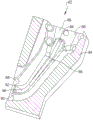
FIG. 2 is a front right perspective view of a semi-permanent mold system according to an exemplary embodiment;
FIG. 3 is a cross-sectional elevation view taken along section 3 of FIG. 2;
FIG. 4 is a cross-sectional side view taken along section 4 of FIG. 3; and is
FIG. 5 is a cross-sectional side view taken along section 4 of FIG. 3; and is
Fig. 6 is a partial cross-sectional perspective view of a gate of the present disclosure.
Detailed Description
The following description is merely exemplary in nature and is not intended to limit the present disclosure, application, or uses.
Referring to FIG. 1, a known system 10 is shown that uses a semi-permanent mold 12, showing an end of the semi-permanent mold 12, to produce a casting 14, such as an aluminum cylinder head for an automotive vehicle internal combustion engine (not shown).
The molten aluminum material is gravity fed to the semi-permanent mold 12 via the feed portion 16. The feed section 16 defines a pouring system including an injection slot 18 that acts like a funnel, injecting molten metal into the injection slot 18. The material flows downwardly out of the injection slot 18 through the gate 20 in a downward direction 22 and transitions into a generally horizontally oriented runner 24. Material flows from runner 24 through a plurality of gates 26 into mold 12.
As the molten metal fills the mold 12, in order to force a volume of cast metal (which may contain porosity) away from the finished casting, the overflow of molten metal creates a riser 28 that is typically located above the mold 12, where the cooling rate is the slowest and, therefore, porosity is most likely to occur. The size and volume of the riser 28 is predetermined to calculate the total volume of molten metal to be added to the injection slot 18 and/or sprue due to expected molten metal shrinkage during cooling. To ensure gravity flow, the height of the injection slot 18 must be predetermined to position the injection slot 18 at or above the maximum desired height of the risers 28. The gates 20 and runners 24 are sized to allow gravity-only flow, mold fill times of about 20 to 22 seconds, and cooling/casting removal times of about 240 seconds.
The volume of metal flushed through the mold 12 to produce the casting 14 and the riser 28 creates an undesirable temperature gradient for solidification and an undesirable metal yield. Furthermore, after the material in the mold 12 and the riser 28 has cooled sufficiently to allow opening of the mold 12 and removal of the casting 14, the riser 28 must then be removed (e.g., by a machining operation). The machining operation removes the risers 28, leaving a machined upper surface 30 of the casting 14.
Referring to fig. 2 and again to fig. 1, a molding system 34 according to the present disclosure uses a semi-permanent mold 36, showing an end of the semi-permanent mold 36, to produce a casting 38, such as an aluminum cylinder head for an automotive vehicle internal combustion engine (not shown). Molten state metal, such as molten aluminum alloy, is gravity fed to semi-permanent mold 36 via feed portion 40, feed portion 40 being modified from feed portion 16 discussed with reference to fig. 1. The feed section 40 includes a sprue slot 42 that functions similarly to the sprue slot 18 to inject molten metal into the sprue slot 42, however the sprue slot 42 may be sized for a smaller volume of molten metal than the sprue slot 18 because no risers are produced during the molding system 34 and therefore no overflow volume for producing risers needs to be added.
The feed portion 40 also includes a forced cooling gate 44. The molten metal flows downwardly through the spout 44 in a downward direction 46, assisted by gravity, out of the injection slot 42 and transitions into a generally horizontally oriented runner 48, the runner 48 communicating with and directing the molten metal into a pouring section 50, from which pouring section 50 the molten metal flows upwardly into the mold 36. Because the casting process of the molding system 34 does not produce risers that require significant filling and cooling time, improved thermal management during mold filling allows for directional solidification of the molten metal from a molten state to a solid state back to the pouring portion 50, runner 48, and gate 44. Also provided in the feed section 40 is a flow choke point 52, the flow choke point 52 predetermining the feed rate of molten metal into the die 36. Molten metal head pressure is maintained in the gate 44 and runner 48 by the choke point 52. The material thickness selected for the gate 44 and the pouring portion 50 controls the heat transfer so that the gate 44 and the pouring portion 50 heat up rapidly during mold filling. This extends the solidification time of the pouring section 50 and the gate 44 beyond the solidification time of the casting 38. The gate 44 and the pouring section 50 will thus serve as the final location in the molding system 34 where the metal is transformed from a molten state to a solid state by cooling.
During mold filling and casting solidification, trapped air insulates the thin-walled mold in the area of the runner 48 and gate 44. Slower cooling times are provided in the pouring section 50, the runner 48 and the gate 44 due to trapped air and the reduced volume and wall thickness of the mold forming the pouring section 50, the runner 48 and the gate 44. Thus, the material in the feed portion 40 will be the last to fully solidify and cool. In order to accelerate solidification of the molten metal in the pouring portion 50, the runner 48, and the gate 44, and thereby allow earlier casting shots, the coolant flushing of the gate 44 is performed after a predetermined period of time has elapsed to allow the casting in the pouring portion 50 to solidify. To effect the coolant flush, the gate 44 is connected to the coolant source 54 via a coolant supply line 56 and a coolant return line 58. Providing a coolant flow to the sprue 44 allows the casting material to directionally solidify toward the pouring portion 50.
The mold 36 is controlled to a temperature of about 300 degrees celsius or greater by a separate mold cooling and heating system (not shown). If there is a cycle interruption, the mold will cool to below the minimum 300 degrees Celsius requirement, so under these conditions the heating system provides additional heat to the gate 44 to reach its minimum set time. For the exemplary aluminum alloy material, the molten injection material was preheated to about 720 degrees celsius, so cooling of the molten metal began immediately during injection. It takes about 10 to 11 seconds to gravity fill mold 36. After the mold is filled, the molten metal is cooled to a typical solidification stage temperature of about 600 degrees celsius and allowed to cool for a period of about 240 seconds. Because the molding system 34 is designed with the material of the sprue portion 50, the runner 48 and gate 44 are eventually cooled to a solid stage to ensure that the material of the sprue portion 50, runner 48 and gate 44 has cooled sufficiently to allow the mold 36 to be opened and a coolant flush of the gate 44 to occur at or near the end of the 240 second cooling period. The coolant provided by the coolant source 54 is preferably air, but may also be water, which cools the metal in the feed portion 40 including the sprue 44 from a typical solidification stage temperature of about 600 degrees celsius to about 450 degrees celsius. The 450 degree celsius gate metal temperature is sufficient to open the mold and hold the gate 44 in place for removal. Thus, when the metal reaches 450 degrees celsius, the gate mold coolant is closed.
A typical molten metal injection weight of about 50 pounds will produce an aluminum cylinder head weighing about 25 pounds. Thus, additional material remains in molding system 34 after removing casting 38. After cooling, the material remaining in the mold 36, the material flashing on the casting 38, and all of the material in the feed portion 40 are removed and reused.
Referring to fig. 3 and again to fig. 2, the gate 44 includes a first half 60 and a second half 62. A first flow passage portion 64 is disposed through the first half 60, and when the two halves are joined, the first flow passage portion 64 communicates with a second flow passage portion 66 created in the second half 62. A coolant jacket 68 defining a cavity is created in the second half 62, extending over the substantial length of the second half 62. The coolant jacket 68 is connected at opposite ends to the coolant supply line 56 and the coolant return line 58 for the coolant source 54. An inlet coolant connector 70 connects the coolant jacket 68 to the coolant supply line 56 and thereby to the coolant source 54. A similar outlet coolant connector shown and described with reference to fig. 6 connects the coolant jacket 68 to the coolant return line 58 to return the flow of coolant to the coolant source 54.
The heat transfer walls of the housing 72 defining the second half 62 separate the flow channel second portion 66 from the coolant jacket 68. The amount of heat transfer available to cool the metal in the second portion 66 of the flow channel is controlled by the wall thickness 74 of the housing 72. According to several aspects, the wall thickness 74 ranges between about 3mm to about 5mm, with a maximum of about 6 mm. The wall thickness 74 is selected to optimize casting solidification. A wall thickness 74 of a minimum of 3mm prevents solidification from occurring too slowly, defined as a total time period of 240 seconds in excess of that allowed for solidification, and also minimizes thermal distortion of the gate 44 at the coolant jacket 68. A wall thickness 74 of a maximum of 6mm prevents solidification from occurring too quickly, defined as solidification of the metal in the mold occurring before solidification in the pouring section 50 or the feeding section 40. The coolant flow to the coolant jacket 68 is started after the molten metal injection is completed and continued for about 20 seconds to completely solidify the material in the gate 44. The material in the infeed section 40 is the last solidified material in the molding system 34, so the coolant flow provided to the gate 44 ensures that the material solidifies and cools to about 300 degrees celsius to allow the mold to be opened and the casting removed.
Referring to fig. 4 and again to fig. 2-3, the first half 60 of the gate 44 includes a body 76, the body 76 having the flow channel first portion 64 formed therethrough. The wide mouth inlet 78 of the flow channel first portion 64 transitions into a central channel 88, the central channel 88 having a smaller cross-section than the inlet 78. The bend 82 changes the direction of flow by about 90 degrees from the central passage 80 and defines an outlet of the flow passage first portion 64. The choke point 52, in combination with the corresponding passage size of the second half 62, defines the minimum passage size of the central passage 80 and is located upstream of the bend 82. The choke point 52 is sized to limit the mass flow rate of the molten metal to provide a mold fill time of about 10 to 11 seconds. The choke point 52 heats up rapidly and helps control the pouring and gate solidification time, allowing directional solidification into the gate 44.
Referring to fig. 5 and again to fig. 2-4, the second half 62 of the gate 44 includes a body 84, the body 84 having the flow channel second portion 66 formed therethrough. The wide mouth inlet 86 of the flow channel second portion 66 transitions into a central channel 88, the central channel 88 having a smaller cross-section than the inlet 86. The bend 90 changes the direction of flow by about 90 degrees from the central passage 88 and defines an outlet of the flow passage second portion 66. The coolant jacket 68 extends substantially the entire length of the flow channel second portion 66 and includes a raised tube portion 92 therethrough, the raised tube portion 92 carrying a flow of coolant between a coolant inlet fitting 94 and a coolant discharge fitting 96. The coolant discharge fitting 96 is preferably provided at a lower position or bottom of the gate 44 and, if the coolant is water, thus effecting the discharge of the coolant from the gate 44.
Referring to fig. 6 and again to fig. 2-5, the coolant jacket 68 extends substantially the entire length 98 of the gate 44, and thus substantially the entire gate 44 is cooled by the coolant flow. Coolant (air or water) enters the inlet coolant fitting 70 via the coolant supply line 56, traverses the coolant jacket 68, includes through the raised tube portion 92, and exits into the coolant return line 58 at the outlet coolant fitting 100 for return to the coolant source 54.
A system and method of casting metal using a semi-permanent mold connected to a pouring section and a charging section of the present disclosure provides several advantages. These advantages include elimination of risers produced in common semi-permanent molding operations to minimize solidification shrinkage porosity, provision of flow chokepoints in the feed portion of the mold system to control molten metal flow rates, predetermination of gate and sprue wall thicknesses to achieve solidification cooling rates and times, thermal management of the design of the gate section of the molding system to the portion that is ultimately cooled to a solidified state to allow directional solidification into the gate, and provision of coolant jackets and coolant flowing into the coolant jackets of the gate to forcibly cool the gate at the end of the mold cooling period prior to opening the mold.
Although exemplary aluminum alloy materials and material melting temperatures are provided herein as examples, the present disclosure and molding system 34 are not limited to these materials or temperatures, and molding system 34 can be used with other metals and metal forming temperatures. The description of the disclosure is merely exemplary in nature and variations that do not depart from the gist of the disclosure are intended to be within the scope of the disclosure. Such variations are not to be regarded as a departure from the spirit and scope of the disclosure.