CN110249271B - Watch case comprising a capsule held in place in an intermediate piece by a back-up ring - Google Patents
Watch case comprising a capsule held in place in an intermediate piece by a back-up ring Download PDFInfo
- Publication number
- CN110249271B CN110249271B CN201880008556.1A CN201880008556A CN110249271B CN 110249271 B CN110249271 B CN 110249271B CN 201880008556 A CN201880008556 A CN 201880008556A CN 110249271 B CN110249271 B CN 110249271B
- Authority
- CN
- China
- Prior art keywords
- collar
- capsule
- intermediate piece
- watch
- tab
- Prior art date
- Legal status (The legal status is an assumption and is not a legal conclusion. Google has not performed a legal analysis and makes no representation as to the accuracy of the status listed.)
- Active
Links
Images


Classifications
-
- G—PHYSICS
- G04—HOROLOGY
- G04B—MECHANICALLY-DRIVEN CLOCKS OR WATCHES; MECHANICAL PARTS OF CLOCKS OR WATCHES IN GENERAL; TIME PIECES USING THE POSITION OF THE SUN, MOON OR STARS
- G04B37/00—Cases
- G04B37/0008—Cases for pocket watches and wrist watches
- G04B37/005—Cases for pocket watches and wrist watches with cover or protection device which can be completely removed, either by lifting off or by sliding, or by turning (protection covers, protection cases also against humidity)
-
- G—PHYSICS
- G04—HOROLOGY
- G04B—MECHANICALLY-DRIVEN CLOCKS OR WATCHES; MECHANICAL PARTS OF CLOCKS OR WATCHES IN GENERAL; TIME PIECES USING THE POSITION OF THE SUN, MOON OR STARS
- G04B37/00—Cases
- G04B37/0008—Cases for pocket watches and wrist watches
- G04B37/0041—Cases for pocket watches and wrist watches the cover or the bottom can slide or turn with a spring action
-
- G—PHYSICS
- G04—HOROLOGY
- G04B—MECHANICALLY-DRIVEN CLOCKS OR WATCHES; MECHANICAL PARTS OF CLOCKS OR WATCHES IN GENERAL; TIME PIECES USING THE POSITION OF THE SUN, MOON OR STARS
- G04B37/00—Cases
- G04B37/04—Mounting the clockwork in the case; Shock absorbing mountings
- G04B37/0427—Mountings relative to pocket and wrist watches allowing a rocking movement about a hinge or any other movement
- G04B37/0463—Free standing watches where the clockwork, on opening or closing the case, is ejected or returned by spring action, or possibly with a spring for opening or closing the case
-
- G—PHYSICS
- G04—HOROLOGY
- G04B—MECHANICALLY-DRIVEN CLOCKS OR WATCHES; MECHANICAL PARTS OF CLOCKS OR WATCHES IN GENERAL; TIME PIECES USING THE POSITION OF THE SUN, MOON OR STARS
- G04B37/00—Cases
- G04B37/04—Mounting the clockwork in the case; Shock absorbing mountings
- G04B37/05—Fixed mountings for pocket or wrist watches
-
- G—PHYSICS
- G04—HOROLOGY
- G04B—MECHANICALLY-DRIVEN CLOCKS OR WATCHES; MECHANICAL PARTS OF CLOCKS OR WATCHES IN GENERAL; TIME PIECES USING THE POSITION OF THE SUN, MOON OR STARS
- G04B37/00—Cases
- G04B37/12—Cases for special purposes, e.g. watch combined with ring, watch combined with button
-
- G—PHYSICS
- G04—HOROLOGY
- G04B—MECHANICALLY-DRIVEN CLOCKS OR WATCHES; MECHANICAL PARTS OF CLOCKS OR WATCHES IN GENERAL; TIME PIECES USING THE POSITION OF THE SUN, MOON OR STARS
- G04B45/00—Time pieces of which the indicating means or cases provoke special effects, e.g. aesthetic effects
- G04B45/0084—Pictures or inscriptions on the case or parts thereof, attaching complete pictures
- G04B45/0092—Changeable parts
-
- G—PHYSICS
- G04—HOROLOGY
- G04G—ELECTRONIC TIME-PIECES
- G04G17/00—Structural details; Housings
- G04G17/08—Housings
Abstract
The invention relates to a watch case comprising a capsule (20) receiving a watch mechanism, the capsule (20) being arranged along a main axis so as to comprise a front side having a dial face, and comprising an intermediate piece (2) surrounding said sealing case (20), the intermediate piece (2) being provided with a substantially cylindrical casing (4) open towards the rear, the intermediate piece (2) receiving the sealing case (20) from one side of the rear, characterized in that it comprises a collar (30) placed against the rear of the capsule (20), the collar (30) comprising a tab (34) arranged on the outer contour (22) of the capsule, the tab (34) being partially inserted in a limiting position in the interior of at least one groove (14) having a circular orientation, the at least one recess (14) is produced in a cylindrical portion of the housing (4) of the intermediate piece (2).
Description
Technical Field
The technical field of the present invention is watchcases and more particularly watches or pocket watches worn on the wrist.
Background
Wrist-worn watches generally comprise a flat, waterproof case, generally circular in shape, having a body that receives on its upper surface a glass covering the dial and the pointer and on its lower surface a back cover.
The case has two arms on each side, which receive between them a transverse stem engaged into a loop of the portion of watchband positioned on that side. One or more crowns arranged on the side have a radial axis that enters the mechanism to ensure the setting and control of the watch.
One known watch type comprises a two-part case comprising: a substantially circular waterproof sealed case (capsule) having a main axis and housing a watch mechanism, the waterproof sealed case including a dial and a glass of the dial on an upper surface thereof; and an intermediate piece forming an outer contour receiving the sealing case, the intermediate piece including a band fastening arm on each side.
The middleware may additionally have an auxiliary function. It is thus possible to specifically change the middleware while maintaining the same sealed case, thereby obtaining watches having different appearances at reduced cost.
According to a known embodiment of this type of watch, the capsule is introduced into the case of the intermediate piece from the front, wherein the circular outer rim of the capsule bears on the front surface of the intermediate piece.
A collar forming a circular ring and provided with an internal thread is then screwed onto a matching thread provided at the rear of the capsule to ensure the axial clamping of the intermediate piece sandwiched between the front outer edge and the collar.
The assembly system is simple and economical to produce and ensures a secure attachment. However, problems arise with this assembly system. In particular, the collar screwed onto the capsule must be circular in order to be screwed, which limits the production of different shapes. Furthermore, the collar may unscrew and fall out without the user noticing it. Furthermore, the retainer ring is a thin part that may easily be warped or screwed askew on the thread of the capsule, which results in a cross-threading of the capsule, which is the most expensive component.
According to another known embodiment of this type of watch, the capsule comprising an outer rim on the front is introduced from the front into an intermediate piece with a lid attached to the intermediate piece by means of lateral pivots, the intermediate piece forming a ring covering the outline of the capsule to hold it in position.
The lid is locked on the intermediate piece by pressing the profile of the sealed box by means of a system of hooks pushed by a spring, which hooks automatically hook when the lid is closed on the intermediate piece.
Thus, a middleware with technical inventive aspects is obtained, which may be adapted to images exhibited by some watch brands.
However, this assembly system is fragile due to the number of parts required to lock the lid, and the behaviour of the assembly system over time is uncertain. Reliability may be particularly limited in a range of motion applications that may involve strong mechanical constraints.
According to a known embodiment of this type of watch, the capsule is inserted in the case of the intermediate piece from the front and is blocked by a ball pushed by a spring which adjusts in a matching recess formed on the contour of the capsule to ensure the axial retention of the capsule.
An additional crown, positioned laterally, passes through the intermediate piece to be screwed in the capsule, providing a complete locking of the capsule.
This is an easy to lock solution, but does not guarantee its long-term reliability. In use, the spring pressing the ball may oxidize, which will limit the service life of the intermediate member. Furthermore, a volume must be provided for accommodating the ball locking means, which involves aesthetic limitations on the intermediate piece.
Disclosure of Invention
The object of the present invention is to remedy the disadvantages of the prior art.
To this end, the invention provides a watch case comprising a capsule receiving a watch mechanism, the capsule being arranged along a main axis so as to comprise a front side having a dial face, and comprising an intermediate piece surrounding such capsule, the intermediate piece having a substantially cylindrical casing open towards the rear, from which it receives the capsule, such case being characterized in that it comprises a collar seated against the rear of the capsule, the collar comprising a tab arranged on the outer contour of the capsule, said tab being partially inserted in a limited position in at least one groove with a circular orientation produced in the cylindrical portion of the casing of the intermediate piece.
One advantage of such a watch case is that, after the introduction of the capsule with the collar arranged on the rear face into the middle part, the tabs are inserted between the capsule and the case of the middle part, the tabs being able to move along a ramp provided on the outer contour of the capsule by rotating the collar, the same tabs being able to be simply radially spaced apart to be introduced into one or more grooves of the case of the middle part having a circular orientation.
An effective and rigid retention of the collar and the capsule in the intermediate piece is obtained economically, since the tabs are axially locked against sliding backwards in the grooves with circular orientation. Furthermore, the tab inserted in the gap between the sealing box and the intermediate piece is not visible, which makes the appearance neat.
The watch case according to the invention may also comprise one or more of the following features, which may be combined together.
The watch case advantageously comprises, with respect to the axis, an angular position for assembling the capsule and the collar by sliding axially in the case of the middle part, and a different angular position for restraining the collar, wherein the tab is partially inserted in the circular groove.
The outer contour of the sealing box advantageously comprises a tab-receiving groove having a bottom which is inclined in the circumferential direction. The tabs can be easily inserted into the grooves of the intermediate piece by sliding along the ramps and by rotating the collar.
The contour of the collar advantageously has markings indicating the assembly angular position and the limit angular position. Thus ensuring the correct limit position of the collar.
More specifically, the tab may have an axial portion from the circular profile of the collar, followed by a circumferential portion arranged to be inserted in the circular groove. Thus, the circumferential portion has radial elasticity.
More specifically, the collar may comprise a circular profile at the rear portion, which incorporates in a step provided around the rear surface of the capsule. This circular profile is then incorporated in the thickness of the sealed box.
In this case, the circular contour of the collar has a conical shape which fits on a matching shape at the bottom of the step of the rear face of the capsule.
The profile of the collar advantageously has a convex shape.
The intermediate piece advantageously comprises a shape for preventing the capsule from rotating. It is therefore possible to easily rotate the retainer ring without driving the seal cartridge to rotate.
In this case, the shape for preventing rotation is advantageously a radial groove which receives a tube which surrounds the axis of the adjustment crown of the seal case.
Another object of the invention is a watch intermediate piece adapted to receive a sealed capsule in a substantially cylindrical housing open towards the rear, housing a watch mechanism, the sealed capsule being retained by a collar seated against the rear of the sealed capsule, the collar comprising a tab arranged on the outer contour of the sealed capsule, such intermediate piece comprising at least one groove with a circular orientation in the cylindrical portion of the housing, said at least one groove being intended to partially receive the tab in a restricted position.
Drawings
Other features and advantages of the invention will become apparent upon reading the following description, given with reference to the accompanying drawings, in which:
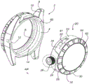
figure 1 shows a watch case according to a first embodiment of the invention, in which the capsule with its collar is separated from the middle part;
figure 2 shows a sealing box profile according to this embodiment;
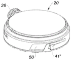
fig. 3 shows a collar according to this embodiment;
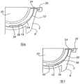
figures 4 and 5 are perspective views of the assembly of the collar on the capsule according to this embodiment, figures 4 and 5 being successively before and after the locking rotation of the assembly; and
figures 6 and 7 are partial sectional rear views of the assembly of the retaining ring according to this embodiment, taken along a cross section through the axis of the crown, figures 6 and 7 being successively before and after the locking rotation of this assembly;
figure 8 shows a watch case according to a second embodiment of the invention, in which the capsule with its collar is separated from the middle part;
figure 9 shows a sealing box profile according to this second embodiment;
fig. 10 shows a collar according to a second embodiment;
figures 11 and 12 are perspective views of an assembly of a collar on a closure according to a second embodiment, figures 11 and 12 being a sequence of before and after the locking rotation of the assembly;
figures 13 and 14 are partial sectional rear views of the assembly of the retaining ring according to the second embodiment, taken along a cross section through the axis of the crown, figures 13 and 14 being successively before and after the locking rotation of the assembly.
For purposes of clarity, the same reference numbers will be used throughout the drawings to refer to the same or like parts.
Detailed Description
Fig. 1 to 2 show a watch case according to a first embodiment, more specifically, middle part 2 comprises a cylindrical casing 4 open towards the rear side marked with an "AR" arrow, so that middle part 2 receives a tightly fitting cylindrical outer contour 22 of sealing case 20. The outer contour 22 of the sealing box 20 may also have another shape than the cylindrical shape shown here.
The housing 4 of the intermediate piece 2 terminates at the front in a circular rim 6 that projects slightly towards the interior of the housing, and the housing 4 forms a support for the front contour of the sealing box 20.
The intermediate piece 2 has two substantially parallel horns 8 on each side, each horn 8 having a punched hole 10 opposite each other and receiving a shank (not shown), also called a pump, housed in a ring of a portion of the bracelet.
One side of the intermediate piece 2 has a radially oriented groove 12, which groove 12 is open towards the rear, so as to receive in an adjusted manner a tube 24 of a stem of a crown 26 surrounding the sealing case 20, which tube 24 is screwed or countersunk in such a sealing case. The assembly comprising tube 24 and crown 26 forms a watch mechanism adjustment knob incorporated in sealed case 20.
The intermediate piece 2 is provided on the contour of its housing 4 with a continuous circular inner groove 14 displaced with respect to the rear end of such a housing. As an alternative solution, the groove 14 may be discontinuous and have different circular portions.
The capsule 20 has a flat rear portion 28, the rear portion 28 comprising a slightly tapered profile which moves away towards the front, forming a small step around such flat rear portion.
The collar 30 comprises a slightly tapered circular profile which cooperates with a tapered profile of the capsule 20 to engage in a step around the flat rear surface 28 and to fit over such rear surface. The retainer ring 30 may be made of cut sheet metal or any other material, such as, for example, a composite material.
The profile of the retainer ring 30 includes a series of radially positioned and angularly distributed raised shapes 32, the raised shapes 32 being gripping means that enable the retainer ring to be rotated by hand.
The rear surface of the intermediate piece 2 has a radial marking 60, which radial marking 60 can be positioned opposite a projection between two recesses 32 in the collar 30, which recesses 32 have markings indicating an "open" unlocked position 62 or a "closed" locked position 64. Of course, these marks may be different in this embodiment and are not limited to etching positions. For example, such etching may be replaced by one or more symbols or any other indicia suitable for such use, i.e., indicative of a locked state.
Fig. 3 shows a retaining ring 30, the outer contour of which 30 comprises a number of angularly distributed tabs 34, the tabs 34 being oriented towards the front and having an overall cylindrical shape, each tab 34 comprising, in succession from such a contour, an axial portion and a circumferential portion 38, the end of the circumferential portion 38 comprising a small projection 40 facing the axis. The tabs 34 are arranged to be adjusted in the cylindrical housing 4 of the intermediate piece 2 by sliding axially from the rear side.
Fig. 4 and 5 show the sealing box 20, the cylindrical outer contour 22 of the sealing box 20 comprising a number of angularly distributed outer grooves 50, in this embodiment three outer grooves 50, each outer groove 50 comprising a first axial portion 52 open towards the rear. As an alternative solution, a different number of outer grooves 50 and tabs 34 may be provided.
As shown in fig. 4 and 6, in the assembled position, the first portion 52 of each outer groove 50 may receive the entire tab 34 through its thickness.
For each groove 50, the first axial portion 52 extends by a second circumferential portion 54 spaced from the rear surface of the capsule 20, the second circumferential portion 54 having a bottom that gradually rises radially outward in a ramp. The bottom has a recess 41, for example formed by grooves and/or scratches, so that in the assembled position of the collar 30 after the collar 30 has been rotated until restrained, the protrusion 40 can be received in the recess 41. Such a projection 40, in combination with such a recess 41, thus forms means for fixing rotation, which makes it possible to limit the assembly position of the collar 30 with respect to the capsule 20, in order to move in the opposite direction, i.e. the rotation for unlocking the collar 30 with respect to the capsule 20, a safety engagement must be overcome, which requires a predetermined force, as a safety measure ensuring that the collar 30 cannot be pivoted further by friction and/or vibration when the watch is worn on the user's wrist.
The watch case is assembled in the following manner. In a first step, the collar 30 is positioned by fitting the collar 30 on the rear of the capsule 20, wherein each tab 34 is located completely inside the first axial portion 52 of the groove 50.
The sealing box 20 with the collar 30 is then inserted into the housing 4 of the intermediate piece 2. Tube 24 of crown 26 is positioned facing groove 12 of intermediate member 2 to enter such groove. The "on" indicia 62 is opposite the radial indicia 60.
In a subsequent step, the retainer ring is rotated clockwise by hand using the convex shape 32 of the retainer ring 30 to bring the indicia "closed" opposite the radial indicia 60, as shown in fig. 5 and 7.
Thus, the circular portion 38 of each tab 34 engages in the second portion 54 of the matching groove 50 and the circumferential portion is outwardly convex due to the projection 40 bearing on the slope of the bottom of the raised second portion. The projection 40 bears with a reduced surface against the inclined surface of the groove 50, which reduces the friction when rotating the securing ring 30.
The circumferential portion 38 of each tab 34, after the outward radial movement, enters the circular groove 14 of the shell 4 of the intermediate piece 2 and is constrained at the bottom of such groove when the rotation is completed. Sufficient rotation of the collar 30 is ensured by the "off" mark 64 facing the radial line 60, which ensures the confinement of the tab 34 clamped between the bottom of the groove 50 and the bottom of the circular groove 14.
During the rotational movement of collar 30, seal cartridge 20 is kept stationary with respect to intermediate piece 2, in particular by tube 24 of crown 26, integral with seal cartridge 20, tube 24 fitting in groove 12 of such intermediate piece. This makes pivoting of the collar 30 relative to the sealing box 20 and thus displacement of the tab 34 in the groove 50 easier.
The collar 30 and the capsule 20 are thus effectively restrained in the intermediate piece 2 with little risk of disintegration, wear or failure over time.
In general, the limitation of the rotation of the capsule 20 about its axis with respect to the intermediate piece 2 is provided by a tube 24 of the adjusting knob integral with the capsule 20, the tube 24 fitting tightly in the groove 12 of the intermediate piece. The limitation of the translation of the capsule 20 along the axis is provided by the tabs 34 engaging in the circular grooves 14 of the intermediate piece 2. The collar 30 is held in place and bears on the rear of the capsule 20, which confines the capsule 20 in the housing 4 of the intermediate piece 2.
Figures 8 to 14 show a watch case according to a second embodiment. This second embodiment differs from the first embodiment in particular mainly in that the means for fixing the rotation are no longer formed by the projections 40 engaging in the matching recesses 41 in the assembly position after rotation until limited, but by the slots 40 ' provided in the circumferential portion 38 of each tab 34, and in that the matching projections 41 ' engage in the slots 40 ' in the assembly position after rotation until limited.
Such means for fixing rotation make it possible to limit the assembly position of the collar 30 with respect to the capsule 20, in order to move in the opposite direction, i.e. to pivot the collar 30 with respect to the capsule 20 in the unlocking direction, in order to open the casing, a safety engagement that must overcome the fixing assembly and prevent any improper rotation of the collar 30. It should be noted that in the case of the slit 40', the safety catch is positioned along an axis substantially parallel to the axis of the capsule 20, whereas in the case of the projection 40, such safety engagement is substantially radial with respect to said axis, since the slit is substantially axially oriented with respect to the main axis.
The invention has been described above by way of example. It is to be understood that those skilled in the art can carry out different embodiments of the invention without departing from the scope of the invention.
Claims (9)
1. Watch case comprising a capsule (20) to receive a watch mechanism, the capsule (20) being arranged along a main axis so as to comprise a front side with a dial face, and comprising an intermediate piece (2) surrounding the capsule (20), the intermediate piece (2) being provided with a substantially cylindrical casing (4) open towards the rear, the intermediate piece (2) receiving the capsule (20) from one side of the rear, characterized in that it comprises a collar (30) to be placed against the rear of the capsule (20), and in that the collar (30) comprises a tab (34) arranged on the outer contour (22) of the capsule (20), and in that it has, with respect to the axis, a first angular position for assembling the capsule (20) and the collar (30) by sliding axially into the casing (4) of the intermediate piece (2), and a different angular position for limiting the collar (30) In which said tab (34) is partially inserted in at least one inner groove (14) with a circular orientation produced in a cylindrical portion of said housing (4) of said intermediate piece (2) after rotation of said collar (30) with respect to said capsule (20),
wherein the outer contour (22) of the sealing box comprises an outer groove (50) receiving the tab (34), the outer groove (50) of the outer contour (22) of the sealing box having a bottom which is inclined in the circumferential direction.
2. Watch case according to claim 1 characterised in that the collar (30) has markings (62, 64) on its profile indicating the first and second angular positions.
3. Watch case according to claim 1 or 2 characterised in that the tab (34) has an axial portion (36) from the circular profile of the collar (30) and then a circumferential portion (38) arranged to be inserted in the circular internal groove (14).
4. Watch case according to claim 1 or 2 characterised in that the collar (30) comprises on the rear part a circular profile incorporated in a step provided around the rear face (28) of the capsule (20).
5. Watch case according to claim 4 characterised in that the circular profile of the collar (30) has a conical shape which fits on a matching shape at the bottom of the step of the back surface (28) of the sealing case (20).
6. Watch case according to claim 1 or 2 characterised in that the collar (30) has a convex shape (32) on its profile.
7. Watch case according to claim 1 or 2 characterised in that the middle part (2) comprises a shape (12) for preventing the sealing case (20) from rotating.
8. Watch case according to claim 7 characterized in that the shape (12) for preventing the rotation of the sealing case (20) is a radial slot which receives a tube (24) which surrounds the axis of an adjusting crown (26) of the sealing case (20).
9. Watch middle (2), which watch middle (2) is adapted to receive a sealing cartridge (20) in a substantially cylindrical housing (4) open towards the rear, which sealing cartridge (20) accommodates a watch mechanism, and which sealing cartridge (20) is held in place by a collar (30) bearing against the rear of the sealing cartridge (20), and which collar (30) comprises a tab (34) arranged on the outer contour (22) of this sealing cartridge (20), characterized in that the watch middle (2) comprises in its cylindrical part of the housing (4) at least one inner groove (14) with a circular orientation, which at least one inner groove (14) is provided for partially receiving the tab (34) in a restricted position,
wherein the outer contour (22) of the sealing box comprises an outer groove (50) receiving the tab (34), the outer groove (50) of the outer contour (22) of the sealing box having a bottom which is inclined in the circumferential direction.
Applications Claiming Priority (3)
| Application Number | Priority Date | Filing Date | Title |
|---|---|---|---|
| FR1750610A FR3062218B1 (en) | 2017-01-25 | 2017-01-25 | "CAPSLOCK" WATCH FASTENING |
| FR17/50610 | 2017-01-25 | ||
| PCT/FR2018/050174 WO2018138443A1 (en) | 2017-01-25 | 2018-01-25 | Watch case comprising a capsule held in place in a middle by a rear bezel |
Publications (2)
| Publication Number | Publication Date |
|---|---|
| CN110249271A CN110249271A (en) | 2019-09-17 |
| CN110249271B true CN110249271B (en) | 2021-11-12 |
Family
ID=58347677
Family Applications (1)
| Application Number | Title | Priority Date | Filing Date |
|---|---|---|---|
| CN201880008556.1A Active CN110249271B (en) | 2017-01-25 | 2018-01-25 | Watch case comprising a capsule held in place in an intermediate piece by a back-up ring |
Country Status (6)
| Country | Link |
|---|---|
| US (1) | US11449008B2 (en) |
| EP (1) | EP3574377A1 (en) |
| JP (1) | JP7128209B2 (en) |
| CN (1) | CN110249271B (en) |
| FR (1) | FR3062218B1 (en) |
| WO (1) | WO2018138443A1 (en) |
Families Citing this family (6)
| Publication number | Priority date | Publication date | Assignee | Title |
|---|---|---|---|---|
| USD928010S1 (en) * | 2019-06-12 | 2021-08-17 | Marc Balayer | Wristwatch holder with lid and interchangeable ring |
| JP7148897B2 (en) * | 2020-08-05 | 2022-10-06 | カシオ計算機株式会社 | Exterior materials, cases and watches |
| EP3958067A1 (en) | 2020-08-17 | 2022-02-23 | The Swatch Group Research and Development Ltd | Device for attaching a bottom on a middle for a clockpiece |
| EP3974914A1 (en) * | 2020-09-25 | 2022-03-30 | The Swatch Group Research and Development Ltd | Device for locking a movement of a clock piece |
| SE545059C2 (en) * | 2021-07-23 | 2023-03-14 | Ola Stray | Wristwatch |
| EP4163738B1 (en) * | 2021-10-08 | 2024-03-20 | Louis Lang S.A. | Watch case with a bayonet connection |
Citations (4)
| Publication number | Priority date | Publication date | Assignee | Title |
|---|---|---|---|---|
| CN1397855A (en) * | 2001-07-18 | 2003-02-19 | 斯沃奇集团管理服务股份公司 | Device for regulating back screwed on central case element into line of 12 point-6 point shaft |
| EP1635232B1 (en) * | 2004-09-08 | 2008-03-12 | Richemont International S.A. | Wristwatch case |
| CN102608904A (en) * | 2012-03-09 | 2012-07-25 | 莆田市诺斯顿电子发展有限公司 | Electronic watch |
| CN203825380U (en) * | 2014-04-25 | 2014-09-10 | 续嘉 | Watch having replaceable decorative cover |
Family Cites Families (18)
| Publication number | Priority date | Publication date | Assignee | Title |
|---|---|---|---|---|
| US3264820A (en) * | 1963-06-18 | 1966-08-09 | Piquerez Ervin | Shaped watertight watch case fastening means |
| FR2122547A1 (en) * | 1971-11-18 | 1972-09-01 | Bermi Watch Sa | |
| JPS52148166A (en) * | 1976-06-04 | 1977-12-09 | Seiko Epson Corp | Construction of back lid of wrist watch casing |
| JPS5633365Y2 (en) * | 1976-10-18 | 1981-08-07 | ||
| JPS59636Y2 (en) * | 1978-05-01 | 1984-01-09 | セイコーインスツルメンツ株式会社 | mobile watch side |
| JPS5612886U (en) * | 1979-07-10 | 1981-02-03 | ||
| JPS5697777U (en) * | 1979-12-27 | 1981-08-03 | ||
| US5392261A (en) * | 1994-01-26 | 1995-02-21 | Hsu; Wen-Tung | Watch assembly |
| JPH09189776A (en) * | 1996-01-11 | 1997-07-22 | Citizen Watch Co Ltd | Module fixing structure of watch |
| TW442714B (en) * | 1999-08-24 | 2001-06-23 | Ebauchesfabrik Eta Ag | Timepiece movement |
| KR200406111Y1 (en) * | 2005-11-01 | 2006-01-20 | 김재섭 | A wristwatch with traffic pass card |
| US7177234B1 (en) * | 2006-04-27 | 2007-02-13 | Gary Paul | Wristwatch with removable face |
| JP5003373B2 (en) * | 2007-09-14 | 2012-08-15 | セイコーエプソン株式会社 | clock |
| DE202008016523U1 (en) * | 2008-12-12 | 2009-03-05 | Dobert, Bernhard | Sleeves or boxes for wristwatches, wristwatches for wristwatches, fastening devices for bracelets, wristwatch with fastening sleeve |
| IT1394429B1 (en) * | 2009-06-17 | 2012-06-15 | New Art Di Mariarosa Fantoni | WRISTWATCH WITH REMOVABLE CASE |
| DE202010013476U1 (en) * | 2010-09-21 | 2011-01-20 | Pilz, Olaf | Clock |
| CN201867593U (en) * | 2010-11-22 | 2011-06-15 | 东莞凤岗雁田金光五金塑胶制品厂 | Novel combined type watch |
| EP2874022B1 (en) * | 2013-11-15 | 2016-10-26 | Chopard Technologies SA | Watch case including a bayonet connection |
-
2017
- 2017-01-25 FR FR1750610A patent/FR3062218B1/en active Active
-
2018
- 2018-01-25 JP JP2019560491A patent/JP7128209B2/en active Active
- 2018-01-25 US US16/480,774 patent/US11449008B2/en active Active
- 2018-01-25 CN CN201880008556.1A patent/CN110249271B/en active Active
- 2018-01-25 WO PCT/FR2018/050174 patent/WO2018138443A1/en unknown
- 2018-01-25 EP EP18706783.0A patent/EP3574377A1/en active Pending
Patent Citations (4)
| Publication number | Priority date | Publication date | Assignee | Title |
|---|---|---|---|---|
| CN1397855A (en) * | 2001-07-18 | 2003-02-19 | 斯沃奇集团管理服务股份公司 | Device for regulating back screwed on central case element into line of 12 point-6 point shaft |
| EP1635232B1 (en) * | 2004-09-08 | 2008-03-12 | Richemont International S.A. | Wristwatch case |
| CN102608904A (en) * | 2012-03-09 | 2012-07-25 | 莆田市诺斯顿电子发展有限公司 | Electronic watch |
| CN203825380U (en) * | 2014-04-25 | 2014-09-10 | 续嘉 | Watch having replaceable decorative cover |
Also Published As
| Publication number | Publication date |
|---|---|
| JP2020506403A (en) | 2020-02-27 |
| FR3062218A1 (en) | 2018-07-27 |
| CN110249271A (en) | 2019-09-17 |
| FR3062218B1 (en) | 2020-11-27 |
| EP3574377A1 (en) | 2019-12-04 |
| US11449008B2 (en) | 2022-09-20 |
| JP7128209B2 (en) | 2022-08-30 |
| WO2018138443A1 (en) | 2018-08-02 |
| US20200019120A1 (en) | 2020-01-16 |
Similar Documents
| Publication | Publication Date | Title |
|---|---|---|
| CN110249271B (en) | Watch case comprising a capsule held in place in an intermediate piece by a back-up ring | |
| CN104412176B (en) | Rotating bezel system | |
| JP6694943B2 (en) | Watch case with replaceable rotating bezel | |
| US7434984B2 (en) | Timepiece | |
| US7591582B2 (en) | Watch and crown used in this watch | |
| US10228656B2 (en) | Screw-down orientable crown | |
| US20100142333A1 (en) | Portable device and portable watch | |
| JP2000511637A (en) | Locks and waterproof members for rotating bezels of watches, especially underwater watches | |
| JP2007522461A (en) | Watch crown protector | |
| KR20080043318A (en) | Device for fixing a back on a watch middle | |
| US10345762B2 (en) | Timepiece with retractable pusher | |
| US20190294114A1 (en) | Annular rotating bezel system comprising a spring ring | |
| JP2008076067A (en) | Watch | |
| US20190324405A1 (en) | Locking system for a control element of a timepiece | |
| US20120120777A1 (en) | Timepiece | |
| CN111427251B (en) | Orientable back cover for a timepiece | |
| US11625006B2 (en) | Rotating bezel blocking device | |
| US11150606B2 (en) | Timepiece including a device for locking a valve or a winding button | |
| JP6123826B2 (en) | Electronic equipment and watches | |
| JP4595382B2 (en) | Watch case and watch | |
| US20220260954A1 (en) | Watch equipped with a device for locking an external control unit | |
| CN111381482B (en) | Watch case provided with an annular ring, watch and watch assembly set comprising such a case | |
| US20230038234A1 (en) | Orientable back for a timepiece | |
| JPS6344778Y2 (en) | ||
| JP2000329868A (en) | Timepiece structure |
Legal Events
| Date | Code | Title | Description |
|---|---|---|---|
| PB01 | Publication | ||
| PB01 | Publication | ||
| SE01 | Entry into force of request for substantive examination | ||
| SE01 | Entry into force of request for substantive examination | ||
| REG | Reference to a national code |
Ref country code: HK Ref legal event code: DE Ref document number: 40011672 Country of ref document: HK |
|
| GR01 | Patent grant | ||
| GR01 | Patent grant |