CN110118552B - Position detection device and position detection method - Google Patents
Position detection device and position detection method Download PDFInfo
- Publication number
- CN110118552B CN110118552B CN201910083033.XA CN201910083033A CN110118552B CN 110118552 B CN110118552 B CN 110118552B CN 201910083033 A CN201910083033 A CN 201910083033A CN 110118552 B CN110118552 B CN 110118552B
- Authority
- CN
- China
- Prior art keywords
- absolute
- absolute value
- track
- increment
- value
- Prior art date
- Legal status (The legal status is an assumption and is not a legal conclusion. Google has not performed a legal analysis and makes no representation as to the accuracy of the status listed.)
- Active
Links
Images


Classifications
-
- G—PHYSICS
- G01—MEASURING; TESTING
- G01C—MEASURING DISTANCES, LEVELS OR BEARINGS; SURVEYING; NAVIGATION; GYROSCOPIC INSTRUMENTS; PHOTOGRAMMETRY OR VIDEOGRAMMETRY
- G01C21/00—Navigation; Navigational instruments not provided for in groups G01C1/00 - G01C19/00
- G01C21/04—Navigation; Navigational instruments not provided for in groups G01C1/00 - G01C19/00 by terrestrial means
- G01C21/08—Navigation; Navigational instruments not provided for in groups G01C1/00 - G01C19/00 by terrestrial means involving use of the magnetic field of the earth
-
- G—PHYSICS
- G01—MEASURING; TESTING
- G01D—MEASURING NOT SPECIALLY ADAPTED FOR A SPECIFIC VARIABLE; ARRANGEMENTS FOR MEASURING TWO OR MORE VARIABLES NOT COVERED IN A SINGLE OTHER SUBCLASS; TARIFF METERING APPARATUS; MEASURING OR TESTING NOT OTHERWISE PROVIDED FOR
- G01D5/00—Mechanical means for transferring the output of a sensing member; Means for converting the output of a sensing member to another variable where the form or nature of the sensing member does not constrain the means for converting; Transducers not specially adapted for a specific variable
- G01D5/12—Mechanical means for transferring the output of a sensing member; Means for converting the output of a sensing member to another variable where the form or nature of the sensing member does not constrain the means for converting; Transducers not specially adapted for a specific variable using electric or magnetic means
- G01D5/14—Mechanical means for transferring the output of a sensing member; Means for converting the output of a sensing member to another variable where the form or nature of the sensing member does not constrain the means for converting; Transducers not specially adapted for a specific variable using electric or magnetic means influencing the magnitude of a current or voltage
- G01D5/16—Mechanical means for transferring the output of a sensing member; Means for converting the output of a sensing member to another variable where the form or nature of the sensing member does not constrain the means for converting; Transducers not specially adapted for a specific variable using electric or magnetic means influencing the magnitude of a current or voltage by varying resistance
Landscapes
- Engineering & Computer Science (AREA)
- Remote Sensing (AREA)
- Physics & Mathematics (AREA)
- General Physics & Mathematics (AREA)
- Radar, Positioning & Navigation (AREA)
- Life Sciences & Earth Sciences (AREA)
- Environmental & Geological Engineering (AREA)
- General Life Sciences & Earth Sciences (AREA)
- Geology (AREA)
- Automation & Control Theory (AREA)
- Transmission And Conversion Of Sensor Element Output (AREA)
Abstract
The invention provides a position detection device and a position detection method capable of accurately calculating an absolute position even when a magnetic sensor device is inclined relative to a magnetic scale. The magnetic scale (2) is provided with a first absolute track (21) and a second absolute track (22) whose patterns are offset by half the pitch. The magnetic sensor device (3) is provided with an increment signal correction unit (43) that outputs a corrected increment signal (C_INC) in which the phase shift is corrected when the phase of the increment signal (INC) is shifted. A calculation unit (44) for calculating the absolute position uses a first absolute value (ABS 1) from the first absolute track (21) in the calculation of the absolute position when the correction incremental signal (C_INC) reaches a central value from zero, uses a second absolute value (ABS 2) from the second absolute track (22) in the calculation of the absolute position when the correction incremental signal (C_INC) reaches a maximum value from the central value.
Description
Technical Field
The present invention relates to a position detection device and a position detection method for a position detection device, which detect the position of a relatively moving magnetic scale by a magnetic sensor device.
Background
A position detecting device for outputting an absolute value is described in patent document 1. The position detector of this document includes a magnetic sensor device and a magnetic scale that moves relative to the magnetic sensor device. The magnetic scale includes absolute tracks on which absolute patterns are formed at a predetermined pitch in a relative movement direction, and incremental tracks which are arranged side by side with the absolute tracks and on which incremental patterns are formed at a pitch corresponding to the absolute patterns. The magnetic sensor device includes an absolute value output unit that reads an absolute track and outputs an absolute value, an incremental signal output unit that reads an incremental track and outputs a periodic incremental signal, and a calculation unit that calculates an absolute position of the magnetic scale based on the absolute value and the incremental signal. The absolute value output unit includes a magnetic sensor for acquiring an absolute signal for reading an absolute pattern, and the incremental signal output unit includes a magnetic sensor for acquiring an incremental signal for reading an incremental pattern.
The absolute pattern is a pattern in which magnetized and non-magnetized regions are arranged in a non-repeating pattern of a certain pitch. The magnetic sensor for acquiring an absolute signal includes a plurality of magnetoresistive elements having a magnetic sensing direction oriented in a relative movement direction. The plurality of magnetoresistive elements are arranged in the relative movement direction at the same pitch as the non-repeating pattern, and detect magnetic fields of the plurality of regions when the magnetic scale and the magnetic sensor are relatively moved. The absolute value output unit outputs an M-series irregular cyclic random code of a plurality of bits, in which the theoretical value of a region where the signal output from each magnetoresistive element is equal to or greater than a predetermined threshold value is 1 and the region where the signal does not exceed the predetermined threshold value is 0. The calculation unit calculates the absolute position of the magnetic scale or the magnetic sensor device based on the phase and the absolute value of the increment signal.
Prior art literature
Patent literature
Patent document 1: japanese patent application laid-open No. 2017-102089
Disclosure of Invention
Technical problem to be solved by the invention
The magnetic scale includes an absolute track and an incremental track arranged in parallel, and in a position detection device including a magnetic sensor element for acquiring an absolute signal and a magnetic sensor element for acquiring an incremental signal arranged in a direction orthogonal to a relative movement direction in a magnetic sensor device, there is a problem that an absolute position cannot be accurately calculated when the magnetic sensor device is tilted in the relative movement direction with respect to the posture of the magnetic scale. That is, when the posture of the magnetic sensor device relative to the magnetic scale is inclined in the relative movement direction, the position of the magnetic sensor element for absolute signal acquisition and the position of the magnetic sensor element for incremental signal acquisition are shifted in the relative movement direction. Thereby, the phase of the increment signal is shifted from the absolute value acquisition timing at which the new absolute value is acquired. Therefore, the absolute position calculated based on the absolute value and the increment signal is an erroneous value.
In view of the above, an object of the present invention is to provide a position detecting device capable of accurately calculating an absolute position even when an installation posture of a magnetic sensor device is inclined with respect to a relative movement direction of a magnetic scale. Further, a position detection method of such a position detection device is provided.
Technical proposal adopted for solving the problems
In order to solve the above-described problems, the present invention provides a position detection device including a magnetic scale and a magnetic sensor device, the magnetic scale including: an absolute track having an absolute pattern in which magnetized areas and non-magnetized areas are arranged at a first pitch; and an incremental track having an incremental pattern in which magnetized areas and non-magnetized areas are alternately arranged and being provided side by side with the absolute track, the magnetic sensor device includes: an absolute value output unit for reading the absolute track of the magnetic scale that moves relatively and outputting an absolute value; an incremental signal output unit for reading the incremental track of the magnetic scale which moves relatively and outputting a periodic incremental signal which changes from zero to a predetermined maximum value; and a calculation unit that calculates an absolute position based on the absolute value and the increment signal, wherein the position detection device includes an increment signal correction unit that corrects the increment signal, the increment signal correction unit obtains an offset amount by which an actual increment start time of the increment signal is offset from a reference increment start time set in advance as an increment start time of the increment signal start increment, and generates a corrected increment signal in which a phase offset of the increment signal is corrected based on the offset amount, and the calculation unit uses the corrected increment signal in the calculation of the absolute position.
According to the present invention, when the increment start time at which the increment signal actually output from the increment signal output unit starts increment is shifted from the predetermined reference increment start time due to the inclination of the installation posture of the magnetic sensor device with respect to the relative movement direction of the magnetic scale or the like, the increment signal correction unit generates a corrected increment signal in which the phase shift of the increment signal is corrected based on the shift amount. The calculation unit uses the correction increment signal for calculating the absolute position. Thus, the absolute position calculated by the calculating unit is a correct value.
In the present invention, it is preferable that the absolute track includes: a first track having the absolute pattern; and a second track having the absolute pattern shifted from the first track by a second pitch in a relative movement direction and provided alongside the first track, the second pitch being half of the first pitch, the absolute value output section having a first absolute value output section that reads the first track and outputs a first absolute value and a second absolute value output section that reads the second track and outputs a second absolute value, the reference increment start timing being a timing at which the magnetic scale and the magnetic sensor device relatively move by 1/4 pitch of the first pitch from a first absolute value output timing at which the first absolute value output section outputs a new absolute value, the calculation section using the first absolute value from a timing at which the correction increment signal is 0 to a central value at which the correction increment signal reaches zero and the maximum value, the calculation section using the first absolute value in the calculation of the absolute position, the calculation section using the second absolute value in the calculation of the absolute position.
Accordingly, on the absolute track, the absolute pattern of the first track for obtaining the first absolute value and the absolute pattern of the second track for obtaining the second absolute value are shifted by half a pitch (second pitch) in the relative movement direction of the magnetic scale and the magnetic sensor device. The increment signal output by the increment signal output unit starts to increment from the moment when the magnetic scale and the magnetic sensor device output the new first absolute value of the absolute value from the first absolute value output unit by 1/4 pitch of the first pitch. The calculation unit that calculates the absolute position based on the absolute value and the correction increment signal uses the first absolute value for calculating the absolute position from the time when the increment of the correction increment signal starts to the time when the correction increment signal reaches the central value, and uses the second absolute value for calculating the absolute position from the time when the correction increment signal reaches the central value to the time when the correction increment signal reaches the maximum value. Thus, the calculation section does not use the first absolute value obtained by detecting the boundary of each pattern region existing at each first pitch in the absolute pattern of the first track when calculating the absolute position. The calculation unit does not use the second absolute value obtained by detecting the boundary of each pattern region existing at each first pitch in the absolute pattern of the second track. Here, since the magnetic field is unstable at the boundary of each pattern region for each first pitch in the absolute pattern of the first track and the absolute pattern of the second track, the first absolute value and the second absolute value obtained by detecting the boundary of each pattern region may be inaccurate values. In contrast, if the calculating unit does not use the first absolute value and the second absolute value obtained by detecting the boundary of each pattern region when calculating the absolute position, the absolute position can be calculated using an accurate absolute value (first absolute value or second absolute value).
In the present invention, the incremental track may have an incremental pattern in which N poles and S poles are alternately magnetized at the second pitch in the relative movement direction. Accordingly, the period of acquiring the absolute value and the period of the increment signal can be easily matched.
In the present invention, the increment signal correction unit may acquire the offset based on a first value of the increment signal at a first time when the first absolute value and the second absolute value are changed from the same value to different values and a second value of the increment signal at a second time when the first absolute value and the second absolute value at the first time are returned to the same value. Accordingly, since the offset amount can be easily obtained, the generation of the corrected incremental signal by the incremental signal correction unit becomes easy.
In the present invention, the increment signal correction unit may acquire the offset based on a third value of the increment signal at a third time when the first absolute value and the second absolute value change from different values to the same value and a fourth value of the increment signal at a fourth time when the first absolute value and the second absolute value at the third time are returned to different values. Accordingly, since the offset amount can be easily obtained, the generation of the corrected incremental signal by the incremental signal correction unit becomes easy.
Next, the present invention provides a position detection method for a position detection device including a magnetic scale and a magnetic sensor device, the magnetic scale including: an absolute track having an absolute pattern in which magnetized areas and non-magnetized areas are arranged at a first pitch; and an incremental track having an incremental pattern in which magnetized areas and non-magnetized areas are alternately arranged and being provided side by side with the absolute track, the magnetic sensor device includes: an absolute value output unit for reading the absolute track of the magnetic scale that moves relatively and outputting an absolute value; and an incremental signal output unit that reads the incremental track of the magnetic scale that moves relatively and outputs a periodic incremental signal that changes from zero to a predetermined maximum value, wherein the position detection device calculates an absolute position based on the absolute value and the incremental signal, wherein the position detection method is characterized in that an incremental start time at which the incremental signal starts to increment is set in advance as a reference incremental start time, an offset amount by which an actual incremental start time of the incremental signal deviates from the reference incremental start time is obtained, a correction incremental signal in which a phase offset of the incremental signal is corrected is generated based on the offset amount, and the correction incremental signal is used for calculation of the absolute position.
According to the present invention, when the increment start time at which the increment signal actually output from the increment signal output unit starts to increment is shifted from the predetermined reference increment start time due to the inclination of the installation posture of the magnetic sensor device with respect to the relative movement direction of the magnetic scale or the like, a correction increment signal in which the phase shift of the increment signal is corrected is generated based on the shift amount. In addition, the calculation of the absolute position uses a correction increment signal. Therefore, the absolute position calculated by the calculating unit is a correct value.
In the present invention, it is preferable that the absolute track is provided with: a first track having the absolute pattern; and a second track having the absolute pattern shifted from the first track by a second pitch, which is half of the first pitch, and which is provided in parallel with the first track, and which has, as the absolute value output section, a first absolute value output section that reads the first track and outputs a first absolute value and a second absolute value output section that reads the second track and outputs a second absolute value, the reference increment start time being set to: the magnetic scale and the magnetic sensor device are relatively shifted by 1/4 pitch of the first pitch from a first absolute value output timing at which the first absolute value output unit outputs a new absolute value, the first absolute value is used for calculating the absolute position from a timing at which the correction increment signal is 0 to a central value at which the correction increment signal reaches zero and a center of the maximum value, the maximum value is reached by the correction increment signal from a timing at which the correction increment signal reaches the central value, and the second absolute value is used for calculating the absolute position.
Accordingly, on the absolute track, the absolute pattern of the first track for obtaining the first absolute value and the absolute pattern of the second track for obtaining the second absolute value are shifted by half a pitch (second pitch) in the relative movement direction of the magnetic scale and the magnetic sensor device. In addition, the increment signal starts to increment from the moment when the magnetic scale and the magnetic sensor device are relatively shifted by 1/4 pitch of the first pitch from the first absolute value output moment. In calculating the absolute position, the first absolute value is used for calculating the absolute position from the time when the increment of the correction increment signal starts to the time when the correction increment signal reaches the central value, and the second absolute value is used for calculating the absolute position from the time when the correction increment signal reaches the central value to the time when the correction increment signal reaches the maximum value. Therefore, in calculating the absolute position, neither the first absolute value obtained by detecting the boundary of each pattern region existing at each first pitch in the absolute pattern of the first track nor the second absolute value obtained by detecting the boundary of each pattern region existing at each first pitch in the absolute pattern of the second track is used. Here, since the magnetic field is unstable at the boundary of each pattern region for each first pitch in the absolute pattern of the first track and the absolute pattern of the second track, the first absolute value and the second absolute value obtained by detecting the boundary of each pattern region may be inaccurate values. On the other hand, if the first absolute value and the second absolute value obtained by detecting the boundary of each pattern region are not used in the calculation of the absolute position, the absolute position can be calculated using an accurate absolute value (first absolute value or second absolute value).
In the present invention, the incremental track may have an incremental pattern in which N poles and S poles are alternately magnetized at the second pitch in the relative movement direction. Accordingly, the period of acquiring the absolute value and the period of the increment signal can be easily matched.
In the present invention, the offset amount may be acquired based on a first value of the increment signal at a first time point at which the first absolute value and the second absolute value are changed from the same value to different values and a second value of the increment signal at a second time point at which the first absolute value and the second absolute value return to the same value. Accordingly, since the offset amount can be easily obtained, generation of the correction increment signal becomes easy.
In the present invention, the increment signal correction unit may acquire the offset based on a third value of the increment signal at a third time when the first absolute value and the second absolute value change from different values to the same value and a fourth value of the increment signal at a fourth time when the first absolute value and the second absolute value at the third time are returned to different values. Accordingly, since the offset amount can be easily obtained, generation of the correction increment signal becomes easy.
Effects of the invention
According to the present invention, when the increment start time at which the increment signal starts to be incremented is shifted from the predetermined reference increment start time due to the relative movement direction of the magnetic scale being inclined or the like of the installation posture of the magnetic sensor device, a correction increment signal in which the phase shift of the increment signal is corrected is generated based on the shift amount. In addition, the calculation of the absolute position uses a correction increment signal. Therefore, the absolute position calculated by the calculating unit is a correct value.
Drawings
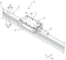
Fig. 1 is an explanatory diagram of a magnetic encoder apparatus to which the present invention is applied.
Fig. 2 (a) and 2 (b) are explanatory views of the track of the magnetic scale and the sensor substrate of the magnetic sensor device.
Fig. 3 is a block diagram of a control system of the magnetic encoder apparatus.
Fig. 4 (a), 4 (b), 4 (c) and 4 (d) are explanatory diagrams of respective signals and values acquired by the magnetic sensor device.
Fig. 5 is a flowchart of the absolute position calculation operation.
Description of the reference numerals
1 … magnetic encoder device (position detecting device), 2 … magnetic scale, 3 … magnetic sensor device, 5 … track, 7 … holder, 8 … cable, 9 … facing surface, 9a … opening, 10 … magnetic sensor, 11 … sensor substrate, 12 … absolute signal acquisition magnetic sensor, 13 … incremental signal acquisition magnetic sensor, 15 … absolute track, 16 … incremental track, 17 … first incremental track, 18 … second incremental track, 17a … first incremental pattern, 18a … second incremental pattern, 21 … first absolute track, 21a … first absolute pattern, 22 … second absolute track, 22a … second absolute pattern, 31 … first magnetic resistance pattern, 32 … second magnetic resistance pattern, 34 (-a) … -signal detection magnetic resistance pattern, 34 (+b) 5237+ signal detection magnetic resistance pattern a magnetoresistive pattern for 34 (-b) … COS-signal detection, a magnetoresistive pattern for 34 (+a) … SIN+ signal detection, a 37 … first absolute value output portion, a 38 … second absolute value output portion, a 39 … increment signal output portion, a 40 … arithmetic processing portion, a 41 … absolute value acquisition portion, a 42 … increment signal acquisition portion, a 43 … increment signal correction portion, a 44 … calculation portion, a 45 … first absolute value acquisition portion, a 46 … second absolute value acquisition portion, an ABS1 … first absolute value, an ABS2 … second absolute value, a CORD1 … first random-cycle code, a CORD2 … second random-cycle code, a first value of an INC1 … increment signal INC, a second value of an INC2 … increment signal INC, a third value of INC3 … increment signal INC, a fourth value of INC4 … increment signal INC, a P1 … first pitch, a P2 … second pitch, a first period …, T2 … second period.
Detailed Description
Hereinafter, a magnetic encoder device to which an embodiment of a position detection device according to the present invention is applied will be described with reference to the drawings.
Fig. 1 is an explanatory view illustrating a magnetic encoder apparatus to which the present invention is applied. Fig. 2 (a) is an explanatory view of tracks provided on the magnetic scale, and fig. 2 (b) is an explanatory view of a sensor substrate of the magnetic sensor device that reads the tracks.
As shown in fig. 1, a magnetic encoder device 1 (position detection device) of the present example includes a magnetic scale 2 and a magnetic sensor device 3 that reads the magnetic scale 2. The magnetic scale 2 is provided with a track 5 extending in the direction of relative movement between the magnetic scale 2 and the magnetic sensor device 3. The magnetic sensor device 3 detects a change in the magnetic field formed on the surface of the magnetic scale 2 when the magnetic scale 2 moves relatively, and outputs the absolute movement position of the magnetic scale 2 or the magnetic sensor device 3. In the following description, the relative movement direction of the magnetic scale 2 and the magnetic sensor device 3 is referred to as the X direction, and the orthogonal direction orthogonal to the X direction is referred to as the Y direction.
The magnetic sensor device 3 includes a holder 7 made of a nonmagnetic material and a cable 8 extending from the holder 7. The holder 7 includes an opposing surface 9 that faces the magnetic scale 2. The facing surface 9 is provided with an opening 9a. The magnetic sensor 10 is disposed in the opening 9a. As shown in fig. 2 (b), the magnetic sensor 10 includes a sensor substrate 11 such as a silicon substrate or a ceramic substrate, and a plurality of magnetic sensing elements 12 and 13 formed on the sensor substrate 11 on a substrate surface facing the magnetic scale 2. The magnetically sensitive elements 12 and 13 have, for example, magnetoresistive elements each having a permalloy film as a magnetically sensitive film. The magnetic induction elements 12 and 13 face the magnetic scale 2 with a predetermined gap.
The magnetic encoder device 1 has one of the magnetic scale 2 and the magnetic sensor device 3 disposed on the fixed body side and the other disposed on the movable body side. In this example, the magnetic scale 2 is disposed on the moving body side, and the magnetic sensor device 3 is disposed on the fixed body side.
(magnetic ruler)
As shown in fig. 2 (a), the track 5 has an absolute track 15 and an incremental track 16 extending in the X-direction, which is the relative movement direction of the magnetic scale 2 and the magnetic sensor device 3. The absolute track 15 and the incremental track 16 are arranged side by side and extend in parallel in the X-direction. The absolute track 15 includes a first absolute track 21 (first track) and a second absolute track 22 (second track) arranged side by side. The incremental track 16 includes a first incremental track 17 and a second incremental track 18 arranged side by side.
The first absolute track 21 has a first absolute pattern 21a formed at a first pitch P1. The first insulating pattern 21a is a pattern in which magnetized areas and non-magnetized areas that are magnetized are arranged in a non-repeating pattern (pseudo random pattern) of a first pitch P1. Each magnetization region constituting one pattern region has an N pole and an S pole in the X direction. The second absolute track 22 of the absolute track 15 has a second absolute pattern 22a of a second pitch P2 shifted by half the first pitch P1 in the relative movement direction with respect to the first absolute pattern 21a of the first absolute track 21. In this example, the first pitch P1 is 0.8mm and the second pitch P2 is 0.4mm.
Here, the first absolute pattern 21a and the second absolute pattern 22a represent M-series random codes of irregular cycles representing absolute positions on the magnetic scale 2 by arrangement of magnetized areas and non-magnetized areas in pattern areas of consecutive n-pitch amounts. More specifically, when the magnetization region is set to a theoretical value of 1 and the non-magnetization region is set to a theoretical value of 0, the M-series irregular cyclic random code is represented by a value by an arrangement of 1 and 0 in the n consecutive regions. In this example, n is 6.
The first incremental track 17 has a first incremental pattern 17a formed at a second pitch P2 which is half of the first pitch P1. The first incremental pattern 17a is a pattern in which N poles and S poles are alternately magnetized at a second pitch P2 in the X direction. The second incremental track 18 has a second incremental pattern 18a formed at a second pitch P2. The second incremental pattern 18a is a pattern in which N poles and S poles are alternately magnetized at a second pitch P2 in the X direction, and the order of magnetization of the N poles and S poles is opposite to that of the first incremental pattern 17a. Therefore, in the Y direction, the N pole of the first delta pattern 17a and the S pole of the second delta pattern 18a are adjacent. In addition, in the Y direction, the S pole of the first incremental pattern 17a and the N pole of the second incremental pattern 18a are adjacent.
(magnetic sensor device)
As shown in fig. 2 (b), the sensor substrate 11 of the magnetic sensor 10 includes a magnetic sensor element 12 for acquiring an absolute signal and a magnetic sensor element 13 for acquiring an incremental signal on a substrate surface facing the magnetic scale 2. The magnetic sensor 12 for absolute signal acquisition and the magnetic sensor 13 for incremental signal acquisition are arranged in the Y direction.
The magnetic sensor 12 for acquiring an absolute signal includes a first magnetoresistive pattern 31 for acquiring a first absolute signal from a first absolute pattern 21a of a first absolute track 21 and a second magnetoresistive pattern 32 for acquiring a second absolute signal from a second absolute pattern 22a of a second absolute track 22. The first and second magneto- resistive patterns 31 and 32 are aligned in the Y direction and extend in parallel in the X direction. When the magnetic sensor device 3 is placed opposite the magnetic scale 2, the first magnetoresistive pattern 31 is placed opposite the first absolute track 21, and the second magnetoresistive pattern 32 is placed opposite the second absolute track 22.
The first and second magnetic resistance patterns 31 and 32 each include a plurality of magnetic resistance elements arranged in the X direction in a posture in which the magnetization direction is oriented in the X direction. The plurality of magnetoresistive elements are arranged at a first pitch P1. The first magneto-resistive pattern 31 sequentially detects the magnetic fields of each of the six regions of the first insulation pattern 21a continuous in the X direction and outputs 6 lines of first insulation signals. Likewise, the second magnetoresistive pattern 32 sequentially detects the magnetic fields of the respective plural regions of the second absolute pattern 22a continuous in the X direction and outputs 6 lines of second absolute signals.
The magneto-inductive element 13 for incremental signal acquisition includes a magnetoresistive pattern 34 (+a) for sin+ signal detection, a magnetoresistive pattern 34 (+b) for cos+ signal detection, a magnetoresistive pattern 34 (-a) for SIN-signal detection, and a magnetoresistive pattern 34 (-b) for COS-signal detection. In this embodiment, the magnetoresistive pattern 34 (+a) for SIN+ signal detection and the magnetoresistive pattern 34 (-b) for COS-signal detection are arranged in the X direction. In addition, the magnetoresistive pattern 34 (+b) for COS+ signal detection and the magnetoresistive pattern 34 (-a) for SIN-signal detection are arranged in the X direction. The magnetoresistive pattern 34 (+a) for sin+ signal detection and the magnetoresistive pattern 34 (+b) for cos+ signal detection are adjacent in the Y direction. The magnetoresistive pattern 34 (-b) for COS-signal detection and the magnetoresistive pattern 34 (-a) for SIN-signal detection are adjacent in the Y direction. When the magnetic sensor device 3 is placed opposite the scale 2, the magnetoresistive pattern 34 (+a) for detecting the sin+ signal and the magnetoresistive pattern 34 (-b) for detecting the COS-signal are placed opposite the first incremental track 17, and the magnetoresistive pattern 34 (+a) for detecting the sin+ signal and the magnetoresistive pattern 34 (-b) for detecting the COS-signal are placed opposite the second incremental track 18.
Here, when the magnetic scale 2 moves relative to the magnetic sensor device 3, the signal output from the magnetoresistive pattern 34 (+a) and the signal output from the magnetoresistive pattern 34 (+b) have a phase difference of 90 ° from each other. The signal output from the magneto-resistive pattern 34 (-a) and the signal output from the magneto-resistive pattern 34 (-b) have a phase difference of 90 ° from each other. The signal output from the magneto-resistive pattern 34 (+a) and the signal output from the magneto-resistive pattern 34 (-a) have a phase difference of 180 °. The signal output from the magneto-resistive pattern 34 (+b) and the signal output from the magneto-resistive pattern 34 (-b) have a phase difference of 180 °.
Fig. 3 is a schematic block diagram showing a control system of the magnetic encoder device 1. Fig. 4 (a), 4 (b), 4 (c) and 4 (d) are explanatory diagrams of respective signals and values obtained by reading the magnetic scale 2 by the magnetic sensor device 3. Fig. 4 (a) is an explanatory diagram of the M-series irregular cyclic random code acquired by the first absolute value acquisition unit and the second absolute value acquisition unit. Fig. 4 (b) is an explanatory diagram of absolute values output by the first absolute value output unit and the second absolute value output unit based on the M-series irregular cyclic random code. Fig. 4 (c) is an explanatory diagram of the increment signal actually output by the increment signal output unit. Fig. 4 (d) is an explanatory diagram of the corrected increment signal generated by the increment signal correction unit. Fig. 5 is a flowchart of the absolute position calculation operation.
As shown in fig. 3, the control system of the magnetic sensor device 3 includes an arithmetic processing unit 40, and the arithmetic processing unit includes CPU, ROM, RAM and the like. In this example, the arithmetic processing unit 40 is mounted on the sensor substrate 11. The input side of the arithmetic processing unit 40 is connected to the magnetic sensor 12 for acquiring absolute signals and the magnetic sensor 13 for acquiring incremental signals. The arithmetic processing unit 40 includes an absolute value acquisition unit 41, an incremental signal acquisition unit 42, an incremental signal correction unit 43, and a calculation unit 44 for calculating an absolute position. The absolute value acquisition unit 41 includes a first absolute value acquisition unit 45 and a second absolute value acquisition unit 46.
Here, the first magnetoresistive pattern 31 and the first absolute value acquiring portion 45 of the magnetic sensor 12 for absolute signal acquisition constitute a first absolute value output portion 37 that reads the first absolute track 21 and outputs the first absolute value ABS1. The second magnetoresistive pattern 32 and the second absolute value acquiring portion 46 of the magnetic sensor 12 for absolute signal acquisition constitute a second absolute value output portion 38 that reads the second absolute track 22 and outputs the second absolute value ABS2. The magnetic sensor 13 for incremental signal acquisition and the incremental signal acquisition unit 42 constitute an incremental signal output unit 39 that reads the incremental track 16 and outputs an incremental signal INC.
First, as shown in fig. 4 (a), the first absolute value acquisition section 45 acquires the first irregular cyclic random code CORD1 of 6 bits based on the 6 lines of the first absolute signals output from the first magnetoresistive pattern 31. Next, as shown in fig. 4 (b), the first absolute value acquisition unit 45 replaces the acquired first irregular cyclic random code CORD1 with an integer number sequence to acquire a first absolute value ABS1. When the first absolute value acquisition section 45 acquires the first absolute value ABS1, the first absolute value output section 37 outputs the first absolute value ABS1.
As shown in fig. 4 (a), the second absolute value acquisition section 46 acquires the second irregular cyclic random code CORD2 of 6 bits based on the 6 lines of the second absolute signal output from the second magnetoresistive pattern 32. Then, as shown in fig. 4 (b), the second absolute value acquisition unit 46 replaces the acquired second irregular cyclic random code CORD2 with an integer number sequence to acquire a second absolute value ABS2. When the second absolute value acquisition portion 46 acquires the second absolute value ABS2, the second absolute value output portion 38 outputs the second absolute value ABS2. As shown in fig. 4 (b), the first absolute value ABS1 from the first absolute value output unit 37 and the second absolute value ABS2 from the second absolute value output unit 38 are output at the timing when the movement distance is shifted by the second pitch P2 when the magnetic scale 2 and the magnetic sensor device 3 are relatively moved.
The incremental signal acquisition unit 42 acquires a sine wave signal based on a signal from the sin+ signal detection magnetoresistive pattern 34 (+a) and a signal from the SIN-signal detection magnetoresistive pattern 34 (-a). The incremental signal acquisition unit 42 acquires a cosine wave signal based on the signal from the magnetoresistive pattern 34 (+b) for cos+ signal detection and the signal from the magnetoresistive pattern 34 (-b) for COS-signal detection. The increment signal acquisition unit 42 performs interpolation and division processing based on the sine wave signal and the cosine wave signal, and generates a periodic increment signal INC that varies from zero to a predetermined maximum value as shown in fig. 4 (c). When the increment signal INC is generated by the increment signal acquisition section 42, the increment signal output section 39 outputs the increment signal INC.
Here, the increment signal INC is set in advance to be incremented from the time At which the magnetic scale 2 and the magnetic sensor device 3 output the new first absolute value ABS1 from the first absolute value output time At0 by the first pitch P1 relative to each other. In this example, the incremental patterns 17a and 18a of the incremental track 16 are shifted by 1/4 pitch from the first absolute pattern 21a of the first absolute track 21 on the magnetic scale 2. Thus, the increment start timing of the increment signal INC is set to a timing At which the magnetic scale 2 and the magnetic sensor device 3 are relatively shifted by 1/4 pitch of the first pitch P1 from the first absolute value output timing At 0. In this example, the maximum value is 8000, and the increment signal INC is counted from zero to 8000.
Next, the increment signal correction unit 43 corrects the increment signal INC when the increment start time It0 of the actual increment signal INC is shifted from the reference increment start time I0, with the time At which the magnetic scale 2 and the magnetic sensor device 3 are relatively shifted by 1/4 pitch of the first pitch P1 from the first absolute value output time At0 being the reference increment start time I0.
Here, the phenomenon in which the increment signal INC actually output from the increment signal output unit 39 is shifted from the preset reference increment start time I0 occurs when the installation posture of the magnetic sensor device 3 is tilted with respect to the X direction, which is the relative movement direction of the magnetic scale 2. That is, the magnetic encoder device 1 includes the absolute track 15 and the incremental track 16 arranged in the Y direction and extending in the X direction on the magnetic scale 2. On the other hand, the magnetic sensor device 3 includes a magnetic sensor element 12 for acquiring absolute signals and a magnetic sensor element 13 for acquiring incremental signals, which are arranged in the Y direction. Therefore, when the installation posture of the magnetic sensor device 3 is tilted in the relative movement direction of the magnetic scale 2 from the posture as the reference, the arrangement of the magnetoresistive pattern (first magnetoresistive pattern 31 and second magnetoresistive pattern 32) of the magnetoresistive element 12 for absolute signal acquisition and the magnetoresistive pattern (sin+ magnetoresistive pattern 34 (+a) for signal detection, cos+ magnetoresistive pattern 34 (+b) for signal detection, SIN-magnetoresistive pattern 34 (-a) for signal detection, and COS-magnetoresistive pattern 34 (-b)) of the magnetoresistive element 13 for incremental signal acquisition are shifted in the X direction. As a result, the increment start time It0 of the actual increment signal INC is shifted from the reference increment start time I0. When the increment start time It0 of the actual increment signal INC is shifted from the reference increment start time I0, there is a problem that the absolute position calculated by the calculation unit 44 becomes an erroneous value. To cope with such a problem, the increment signal correction unit 43 generates a corrected increment signal c_inc in which the phase shift of the increment signal INC is corrected.
As shown in fig. 3, the incremental signal correction unit 43 is provided between the incremental signal output unit 39 and the calculation unit 44. The first absolute value output unit 37, the second absolute value output unit 38, and the increment signal output unit 39 are connected to the input side of the increment signal correction unit 43. The calculation unit 44 is connected to the output side of the incremental signal correction unit 43.
As shown in fig. 5, the increment signal correction unit 43 first acquires an offset E by which the increment start time It0 of the actual increment signal INC is offset from the reference increment start time I0 (step ST 1). In other words, the increment signal correction unit 43 acquires the offset E of the phase of the increment start time It0 of the actual increment signal INC from the time (reference increment start time I0) At which the magnetic scale 2 and the magnetic sensor device 3 are relatively shifted by 1/4 pitch of the first pitch P1 from the first absolute value output time At 0.
Next, the increment signal correction unit 43 generates a corrected increment signal c_inc in which the phase shift of the increment signal INC is corrected, based on the acquired shift amount E (step ST 2). The increment start time of the correction increment signal c_inc coincides with the reference increment start time I0.
When the correction increment signal c_inc is generated, the calculation unit 44 calculates the absolute position using the correction increment signal c_inc (step ST 3).
More specifically, as shown in fig. 4 (c), the increment signal correction unit 43 acquires the offset E based on the first value INC1 of the increment signal INC at the first time t0, at which the first absolute value ABS1 and the second absolute value ABS2 are changed from the same value to different values, and the second value INC2 of the increment signal INC at the second time t2, at which the first absolute value ABS1 and the second absolute value ABS2 return to the same value, following the first time t 0.
That is, when the increment start time It0 coincides with the reference increment start time I0 (the time At which the magnetic scale 2 and the magnetic sensor device 3 relatively move by 1/4 pitch of the first pitch P1 from the first absolute value output time At 0), the time At which the first absolute value ABS1 is newly acquired is the time At which the first absolute value ABS1 and the second absolute value ABS2 change from the same value to the different value, the first time t0 following the first time t0 and the second time t2 returning to the center of the same value. Therefore, the difference (distance D1) between the first value INC1 and the maximum value of the increment signal INC at the first time t0 at which the first absolute value ABS1 and the second absolute value ABS2 change from the same value to different values coincides with the second value INC2 (distance D2 from zero to the second value INC 2) of the increment signal INC at the second time t2 at which the first absolute value ABS1 and the second absolute value ABS2 return to the same value at the first time t 0.
On the other hand, as shown in fig. 4 b and 4 c, when the increment start time It0 is shifted from the reference increment start time I0 (the time when the magnetic scale 2 and the magnetic sensor device 3 are relatively shifted by 1/4 pitch of the first pitch P1 from the first absolute value output time At 0), the difference (distance D1) between the first value INC1 and the maximum value of the increment signal INC At the first time t0 At which the first absolute value ABS1 and the second absolute value ABS2 are changed from the same value to different values, and the second value INC2 (distance D2) of the increment signal INC At the second time t2 At which the first absolute value ABS1 and the second absolute value ABS2 are returned to the same value At the next time t0 are different values. The difference between the difference (distance D1) between the first value INC1 and the maximum value of the increment signal INC and the second value INC2 (distance D2 from zero to the second value INC 2) corresponds to the first absolute value output time At0 and the offset E of the phase of the increment signal INC.
Accordingly, as shown by the arrow in fig. 4 (d), the increment signal correction unit 43 generates a corrected increment signal c_inc in which the phase of the increment signal INC is shifted by the amount corresponding to the shift amount E. Thus, the increment start time in the corrected increment signal c_inc coincides with the reference increment start time I0. The increment signal INC and the corrected increment signal C_INC are phase shifted only, and are counted from zero to a maximum value (8000).
Further, when the increment start time It0 is not shifted from the reference increment start time I0, the offset E is zero. Therefore, the increment signal correction unit 43 directly corrects the increment signal INC as the increment signal c_inc so as not to shift the phase of the increment signal INC.
The increment signal correction unit 43 obtains the offset E when the magnetic sensor device 3 is disposed on the fixed body side and the magnetic scale 2 is disposed on the movable body side, and the magnetic encoder device 1 is installed. That is, in setting, when the magnetic scale 2 and the magnetic sensor device 3 are moved relative to each other by moving the movable body relative to the fixed body, the incremental signal correction unit 43 obtains the difference (distance D1) between the first value INC1 and the maximum value of the incremental signal INC at the first time t0 and the second value INC2 (distance D2 from zero to the second value INC 2) of the incremental signal INC at the second time t2, and calculates the offset E. Then, the increment signal correction unit 43 generates a corrected increment signal c_inc based on the offset E acquired at the time of setting.
Next, the calculating unit 44 calculates the absolute position based on the first and second absolute values ABS1 and ABS2 and the correction increment signal c_inc. Specifically, in the calculation unit 44, the first absolute value ABS1 is used for calculating the absolute position in the first period T1 from the time when the correction increment signal c_inc is 0 to the time when the correction increment signal c_inc reaches the center value at the center of zero and the maximum value, and the second absolute value ABS2 is used for calculating the absolute position in the second period T2 from the time when the correction increment signal c_inc reaches the center value to the time when the correction increment signal c_inc reaches the maximum value.
In this example, the maximum value of the correction increment signal c_inc is 8000. Thus, the central value is 4000. Therefore, in step ST3 of fig. 5 in which the calculating unit 44 calculates the absolute position, the calculating unit 44 monitors the value of the correction incremental signal c_inc when calculating the absolute position (step ST 11), and calculates the absolute position based on the first absolute value ABS1 and the value (phase) of the correction incremental signal c_inc using the first absolute value ABS1 acquired from the first absolute pattern 21a of the first absolute track 21 during the first period T1 in which the value of the correction incremental signal c_inc reaches 4000 from 0 (step ST11: yes). On the other hand, in a second period T2 from 4000 to 8000 in the value of the correction incremental signal C_INC (step ST11: NO), the calculating unit 44 calculates the absolute position based on the second absolute value ABS2 and the value (phase) of the correction incremental signal C_INC by using the second absolute value ABS2 obtained from the second absolute pattern 22a of the second absolute track 22 (step ST 13). That is, the calculation unit 44 alternately switches between the first absolute value ABS1 and the second absolute value ABS2 every time the second pitch P2 is moved when calculating the absolute position as indicated by the arrow in fig. 4 (b).
(effects of action)
In the magnetic encoder device 1 of the present example, when the increment start time It0 of the increment signal INC is shifted from the preset reference increment start time I0 due to the inclination of the installation posture of the magnetic sensor device 3 with respect to the relative movement direction (X direction) of the magnetic scale 2, or the like, the correction increment signal c_inc in which the phase shift of the increment signal INC is corrected is generated based on the shift amount E. In addition, the correction increment signal c_inc is used for the calculation of the absolute position. Therefore, the absolute position calculated by the calculating unit 44 is a correct value.
In the magnetic encoder device 1 of the present example, an accurate absolute value can be used in calculating the absolute position.
That is, in the absolute patterns 21a and 22a of the first absolute track 21 and the second absolute track 22, the magnetic field is unstable at the boundary B (see fig. 4 (a) and 4 (B)) existing in each pattern region of each first pitch P1. Therefore, when the absolute position is calculated by the calculating section 44, when an absolute value obtained by detecting the boundary B of each pattern region with the magnetoresistive element is used as the absolute value, there is a case where the absolute value is inaccurate. If the absolute value is inaccurate, the absolute position cannot be accurately calculated.
In order to cope with such a problem, in the present example, in the absolute track 15, the first absolute pattern 21a of the first absolute track 21 for acquiring the first absolute value ABS1 and the second absolute pattern 22a of the second absolute track 22 for acquiring the second absolute value ABS2 are shifted by half a pitch (second pitch P2) in the X direction of the magnetic scale 2 and the magnetic sensor device 3. In addition, the increment signal INC starts to increment from the time when the magnetic scale 2 and the magnetic sensor device 3 relatively move by 1/4 pitch of the first pitch P1 from the first absolute value output time At 0. When calculating the absolute position, the calculating unit 44 calculates the absolute position based on the first absolute value ABS1 obtained from the first absolute pattern 21a of the first absolute track 21 and the value (phase) of the correction incremental signal c_inc, using the first absolute value ABS1 obtained from the first absolute pattern 21a in the first period T1 in which the value of the correction incremental signal c_inc is from 0 to 4000. On the other hand, the calculation unit 44 uses the second absolute value ABS2 obtained from the second absolute pattern 22a of the second absolute track 22 in the second period T2 from when the value of the correction incremental signal c_inc is 4000 to when the value of the correction incremental signal c_inc reaches 8000.
Therefore, as shown in fig. 4 (B) and 4 (d), the calculation unit 44 does not use the first absolute value ABS1 obtained by detecting the boundary B existing in each pattern region of each first pitch P1 in the first absolute pattern 21a of the first absolute track 21 when calculating the absolute position. Similarly, the calculation unit 44 does not use the second absolute value ABS2 obtained by detecting the boundary B existing in each pattern region of each first pitch P1 in the second absolute pattern 22a of the second absolute track 22 when calculating the absolute position. Therefore, in the calculation section 44, an accurate absolute value (first absolute value ABS1 or second absolute value ABS 2) can be used for the calculation of the absolute position.
In this example, the first and second incremental tracks 17 and 18 each have an incremental pattern 17a and 18a alternately magnetized with an N pole and an S pole at a second pitch P2 in the X direction. Therefore, the period of the reacquiring absolute value and the period of the increment signal INC are easily made uniform.
In addition, in the magnetic encoder device 1 of this example, when the increment start time It0 of the increment signal INC is shifted from the preset reference increment start time I0 due to the inclination of the installation posture of the magnetic sensor device 3 with respect to the relative movement direction (X direction) of the magnetic scale 2, or the like, a correction increment signal c_inc in which the phase shift of the increment signal INC is corrected is generated based on the shift amount E, and the absolute position is calculated using the correction increment signal c_inc. Therefore, when the magnetic encoder device 1 is provided, the positional relationship between the magnetic scale 2 and the magnetic sensor device 3 does not need to be strictly defined. Therefore, the installation work of the magnetic encoder device 1 becomes easy.
(modification)
As shown in fig. 4 (c), the increment signal correction unit 43 may acquire the offset E based on the third value INC3 of the increment signal INC at the third time t3 at which the first absolute value ABS1 and the second absolute value ABS2 change from different values to the same value, and the fourth value INC4 of the increment signal INC at the fourth time t4 at which the first absolute value ABS1 and the second absolute value ABS2 return to different values at the third time t 3.
In this case, the difference (distance D3) between the first value INC1 and the central value of the increment signal INC At the first time t0 At which the first absolute value ABS1 and the second absolute value ABS2 change from different values to the same value, and the difference (distance D4) between the second value INC2 and the central value of the increment signal INC At the second time t2 At which the first absolute value ABS1 and the second absolute value ABS2 return to different values correspond to the offset E of the phases of the first absolute value output time At0 and the increment signal INC.
(other embodiments)
In the magnetic encoder device 1, the incremental signal output unit 39 detects the two incremental tracks 17 and 18 and outputs the incremental signal, but a configuration may be adopted in which the incremental signal is output from one incremental track.
In the magnetic encoder device 1, the increment signal output by the increment signal output unit 39 may be a cursor signal. In this case, two incremental tracks having incremental patterns with different pitches are provided on the magnetic scale, and two incremental signals with different wavelengths are acquired by the magneto-sensitive element 13 for acquiring the incremental signals of the magnetic sensor device. Then, the increment signal output unit 39 generates and outputs a cursor signal having a period longer than the period of the increment signals based on the acquired two increment signals.
Here, the period of the cursor signal is set to a period corresponding to the first pitch P of the absolute pattern. The cursor signal starts to increment from the time when the magnetic scale 2 and the magnetic sensor device 3 output the new first absolute value ABS1 from the first absolute value output time when the first absolute value ABS1 is shifted by 1/4 pitch of the first pitch P.
Claims (6)
1. A position detection device has a magnetic scale and a magnetic sensor device,
the magnetic scale includes: an absolute track having an absolute pattern in which magnetized areas and non-magnetized areas are arranged at a first pitch; and an incremental track having an incremental pattern of alternately arranged magnetized and non-magnetized regions and being arranged side by side with the absolute track,
the magnetic sensor device is provided with: an absolute value output unit for reading the absolute track of the magnetic scale that moves relatively and outputting an absolute value; an incremental signal output unit for reading the incremental track of the magnetic scale which moves relatively and outputting a periodic incremental signal which changes from zero to a predetermined maximum value; and a calculation unit for calculating an absolute position based on the absolute value and the increment signal,
the position detection device is characterized in that,
the position detecting device has an increment signal correction part for correcting the increment signal,
The increment signal correction unit obtains an offset amount by which an actual increment start time of the increment signal is offset from a reference increment start time preset as an increment start time of the increment signal start increment, generates a corrected increment signal in which a phase offset of the increment signal is corrected based on the offset amount,
the calculation section uses the correction increment signal in the calculation of the absolute position,
the absolute track includes: a first track having the absolute pattern; and a second track having the absolute pattern shifted in a relative movement direction with respect to the first track by a second pitch, the second pitch being half of the first pitch, and being arranged side by side with the first track,
the absolute value output unit includes a first absolute value output unit for reading the first track and outputting a first absolute value, and a second absolute value output unit for reading the second track and outputting a second absolute value,
the reference increment start timing is a timing at which the magnetic scale and the magnetic sensor device are relatively shifted by 1/4 pitch of the first pitch from a first absolute value output timing at which the first absolute value output section outputs a new absolute value,
The calculation unit uses the first absolute value in the calculation of the absolute position from the time when the correction increment signal is 0 to the central value at which the correction increment signal reaches zero and the center of the maximum value, uses the second absolute value in the calculation of the absolute position from the time when the correction increment signal reaches the central value to the time when the correction increment signal reaches the maximum value,
the increment signal correction unit obtains the offset based on a first value of the increment signal at a first time when the first absolute value and the second absolute value change from the same value to different values and a second value of the increment signal at a second time when the first absolute value and the second absolute value return to the same value.
2. A position detection device has a magnetic scale and a magnetic sensor device,
the magnetic scale includes: an absolute track having an absolute pattern in which magnetized areas and non-magnetized areas are arranged at a first pitch; and an incremental track having an incremental pattern of alternately arranged magnetized and non-magnetized regions and being arranged side by side with the absolute track,
The magnetic sensor device is provided with: an absolute value output unit for reading the absolute track of the magnetic scale that moves relatively and outputting an absolute value; an incremental signal output unit for reading the incremental track of the magnetic scale which moves relatively and outputting a periodic incremental signal which changes from zero to a predetermined maximum value; and a calculation unit for calculating an absolute position based on the absolute value and the increment signal,
the position detection device is characterized in that,
the position detecting device has an increment signal correction part for correcting the increment signal,
the increment signal correction unit obtains an offset amount by which an actual increment start time of the increment signal is offset from a reference increment start time preset as an increment start time of the increment signal start increment, generates a corrected increment signal in which a phase offset of the increment signal is corrected based on the offset amount,
the calculation section uses the correction increment signal in the calculation of the absolute position,
the absolute track includes: a first track having the absolute pattern; and a second track having the absolute pattern shifted in a relative movement direction with respect to the first track by a second pitch, the second pitch being half of the first pitch, and being arranged side by side with the first track,
The absolute value output unit includes a first absolute value output unit for reading the first track and outputting a first absolute value, and a second absolute value output unit for reading the second track and outputting a second absolute value,
the reference increment start timing is a timing at which the magnetic scale and the magnetic sensor device are relatively shifted by 1/4 pitch of the first pitch from a first absolute value output timing at which the first absolute value output section outputs a new absolute value,
the calculation unit uses the first absolute value in the calculation of the absolute position from the time when the correction increment signal is 0 to the central value at which the correction increment signal reaches zero and the center of the maximum value, uses the second absolute value in the calculation of the absolute position from the time when the correction increment signal reaches the central value to the time when the correction increment signal reaches the maximum value,
the increment signal correction unit obtains the offset based on a third value of the increment signal at a third time when the first absolute value and the second absolute value change from different values to the same value and a fourth value of the increment signal at a fourth time when the first absolute value and the second absolute value return to different values next to the third time.
3. The position detecting apparatus according to claim 1 or 2, wherein,
the incremental track has an incremental pattern of N poles and S poles magnetized alternately at the second pitch in the relative movement direction.
4. A position detecting method is a position detecting method of a position detecting device having a magnetic scale and a magnetic sensor device,
the magnetic scale includes: an absolute track having an absolute pattern in which magnetized areas and non-magnetized areas are arranged at a first pitch; and an incremental track having an incremental pattern of alternately arranged magnetized and non-magnetized regions and being arranged side by side with the absolute track,
the magnetic sensor device is provided with: an absolute value output unit for reading the absolute track of the magnetic scale that moves relatively and outputting an absolute value; and an incremental signal output unit for reading the incremental track of the magnetic scale which moves relatively and outputting a periodic incremental signal which changes from zero to a predetermined maximum value,
the position detection means calculates an absolute position based on the absolute value and the increment signal,
the position detection method is characterized in that,
the increment starting time at which the increment signal starts increment is preset as a reference increment starting time,
An offset amount by which an actual increment start time of the increment signal is offset from the reference increment start time is acquired,
generating a corrected increment signal based on the offset amount, the phase offset of the increment signal being corrected,
the calculation of the absolute position uses the modified delta signal,
the absolute track is provided with: a first track having the absolute pattern; and a second track having the absolute pattern shifted in a relative movement direction with respect to the first track by a second pitch, the second pitch being half of the first pitch, and being arranged side by side with the first track,
further, as the absolute value output unit, a first absolute value output unit for reading the first track and outputting a first absolute value and a second absolute value output unit for reading the second track and outputting a second absolute value are provided in advance,
setting the reference increment start time as: the magnetic scale and the magnetic sensor device are relatively shifted by 1/4 pitch of the first pitch from the first absolute value output timing at which the first absolute value output section outputs the new absolute value,
the absolute position is calculated using the first absolute value from the time when the correction increment signal is 0 to a central value at which the correction increment signal reaches zero and the center of the maximum value, the absolute position is calculated using the second absolute value from the time when the correction increment signal is the central value to the time when the correction increment signal reaches the maximum value,
The offset is acquired based on a first value of the increment signal at a first time when the first absolute value and the second absolute value change from the same value to different values and a second value of the increment signal at a second time when the first absolute value and the second absolute value return to the same value.
5. A position detecting method is a position detecting method of a position detecting device having a magnetic scale and a magnetic sensor device,
the magnetic scale includes: an absolute track having an absolute pattern in which magnetized areas and non-magnetized areas are arranged at a first pitch; and an incremental track having an incremental pattern of alternately arranged magnetized and non-magnetized regions and being arranged side by side with the absolute track,
the magnetic sensor device is provided with: an absolute value output unit for reading the absolute track of the magnetic scale that moves relatively and outputting an absolute value; and an incremental signal output unit for reading the incremental track of the magnetic scale which moves relatively and outputting a periodic incremental signal which changes from zero to a predetermined maximum value,
the position detection means calculates an absolute position based on the absolute value and the increment signal,
The position detection method is characterized in that,
the increment starting time at which the increment signal starts increment is preset as a reference increment starting time,
an offset amount by which an actual increment start time of the increment signal is offset from the reference increment start time is acquired,
generating a corrected increment signal based on the offset amount, the phase offset of the increment signal being corrected,
the calculation of the absolute position uses the modified delta signal,
the absolute track is provided with: a first track having the absolute pattern; and a second track having the absolute pattern shifted in a relative movement direction with respect to the first track by a second pitch, the second pitch being half of the first pitch, and being arranged side by side with the first track,
further, as the absolute value output unit, a first absolute value output unit for reading the first track and outputting a first absolute value and a second absolute value output unit for reading the second track and outputting a second absolute value are provided in advance,
setting the reference increment start time as: the magnetic scale and the magnetic sensor device are relatively shifted by 1/4 pitch of the first pitch from the first absolute value output timing at which the first absolute value output section outputs the new absolute value,
The absolute position is calculated using the first absolute value from the time when the correction increment signal is 0 to a central value at which the correction increment signal reaches zero and the center of the maximum value, the absolute position is calculated using the second absolute value from the time when the correction increment signal is the central value to the time when the correction increment signal reaches the maximum value,
the offset is acquired based on a third value of the increment signal at a third time when the first absolute value and the second absolute value change from different values to the same value and a fourth value of the increment signal at a fourth time when the first absolute value and the second absolute value at the third time are returned to different values.
6. The method for detecting a position according to claim 4 or 5, wherein,
the incremental track is provided with an incremental pattern of N poles and S poles alternately magnetized at the second pitch in the relative movement direction.
Applications Claiming Priority (2)
| Application Number | Priority Date | Filing Date | Title |
|---|---|---|---|
| JP2018020136A JP7085852B2 (en) | 2018-02-07 | 2018-02-07 | Position detection device and position detection method |
| JP2018-020136 | 2018-02-07 |
Publications (2)
| Publication Number | Publication Date |
|---|---|
| CN110118552A CN110118552A (en) | 2019-08-13 |
| CN110118552B true CN110118552B (en) | 2023-06-16 |
Family
ID=67520372
Family Applications (1)
| Application Number | Title | Priority Date | Filing Date |
|---|---|---|---|
| CN201910083033.XA Active CN110118552B (en) | 2018-02-07 | 2019-01-28 | Position detection device and position detection method |
Country Status (2)
| Country | Link |
|---|---|
| JP (1) | JP7085852B2 (en) |
| CN (1) | CN110118552B (en) |
Families Citing this family (5)
| Publication number | Priority date | Publication date | Assignee | Title |
|---|---|---|---|---|
| JP7527211B2 (en) * | 2021-01-20 | 2024-08-02 | ニデックインスツルメンツ株式会社 | Position Detection Device |
| JP7587433B2 (en) * | 2021-02-03 | 2024-11-20 | ニデックインスツルメンツ株式会社 | Position Detection Device |
| JP7688518B2 (en) * | 2021-05-24 | 2025-06-04 | Dmg森精機株式会社 | Magnetic Encoder |
| JP7834464B2 (en) | 2021-12-13 | 2026-03-24 | キヤノン株式会社 | Conveying device |
| CN116659468A (en) * | 2022-02-25 | 2023-08-29 | 住友重机械工业株式会社 | Position measurement switching device, driving device and position measurement switching method |
Family Cites Families (10)
| Publication number | Priority date | Publication date | Assignee | Title |
|---|---|---|---|---|
| JP2571394B2 (en) * | 1987-09-21 | 1997-01-16 | 株式会社マコメ研究所 | Absolute value type magnetic scale device |
| JPH0353114A (en) * | 1989-07-21 | 1991-03-07 | Sony Magnescale Inc | Position detector |
| JPH05168275A (en) * | 1991-12-10 | 1993-07-02 | Nikon Corp | Three-phase AC motor controller |
| JP2004150882A (en) * | 2002-10-29 | 2004-05-27 | Koyo Seiko Co Ltd | Rotation angle detector, and torque detector |
| FR2935486B1 (en) * | 2008-08-28 | 2010-09-10 | Roulements Soc Nouvelle | MAGNETIC ENCODING DEVICE |
| JP6168776B2 (en) * | 2013-01-11 | 2017-07-26 | キヤノン株式会社 | Position control device and position control method |
| JP2015114209A (en) * | 2013-12-12 | 2015-06-22 | セイコーエプソン株式会社 | Encoder and electromechanical device |
| JP2016038294A (en) * | 2014-08-07 | 2016-03-22 | 日本電産サンキョー株式会社 | Magnetic linear encoder |
| JP6487246B2 (en) * | 2015-03-26 | 2019-03-20 | 三菱重工工作機械株式会社 | Electromagnetic induction position detector and position detection method using the same |
| JP6649018B2 (en) * | 2015-09-16 | 2020-02-19 | 日本電産サンキョー株式会社 | Rotary encoder and method for detecting absolute angular position of rotary encoder |
-
2018
- 2018-02-07 JP JP2018020136A patent/JP7085852B2/en active Active
-
2019
- 2019-01-28 CN CN201910083033.XA patent/CN110118552B/en active Active
Also Published As
| Publication number | Publication date |
|---|---|
| JP7085852B2 (en) | 2022-06-17 |
| CN110118552A (en) | 2019-08-13 |
| JP2019138694A (en) | 2019-08-22 |
Similar Documents
| Publication | Publication Date | Title |
|---|---|---|
| CN110118552B (en) | Position detection device and position detection method | |
| EP2999943B1 (en) | System and method for providing signal encoding representative of a signature region in a target and of a direction of rotation | |
| CN108426588B (en) | Rotary encoder and absolute angle position detection method thereof | |
| CN102341675B (en) | Encoder readhead | |
| CN105143831B (en) | Magnetic air type position detecting device and magnetic air type method for detecting position | |
| CN104105951B (en) | Method and apparatus for determining position | |
| US9958294B2 (en) | Absolute position encoder including scale with varying spatial characteristic and utilizing Fourier transform or other signal processing | |
| CN101743456B (en) | Arrangement and method for absolute determination of linear position or rotational position expressed as angle | |
| CN110030924B (en) | Position measuring device | |
| US20190120660A1 (en) | Compact pseudorandom scale and read head for an inductive type absolute position encoder | |
| CN108369113A (en) | position detecting device | |
| CN110118551B (en) | Position detection device and position detection method | |
| Lin et al. | Novel method for determining absolute position information from magnetic patterns | |
| CN109708673B (en) | Separating magnetic encoder based on code pattern | |
| CN102818511B (en) | Linear position is measured system and determines the compartment method along the absolute position of guide rail | |
| JP6334892B2 (en) | POSITION DETECTION DEVICE AND LENS DEVICE AND PHOTOGRAPHING DEVICE HAVING THE SAME | |
| CN114812625B (en) | Position detection device | |
| CN116465437A (en) | Position sensor system and method for detecting errors of the position sensor system | |
| CN114667438A (en) | position measuring device | |
| US20250093144A1 (en) | Inductive position determination system with varying coil geometry, and corresponding position determination method | |
| JP2024075149A (en) | Displacement Detection Device | |
| JP2024006069A (en) | Multi-sensor position measurement system | |
| WO2022185777A1 (en) | Displacement detecting device | |
| JPS63309868A (en) | Phase discriminating circuit | |
| JP2016217782A (en) | Position detection device |
Legal Events
| Date | Code | Title | Description |
|---|---|---|---|
| PB01 | Publication | ||
| PB01 | Publication | ||
| SE01 | Entry into force of request for substantive examination | ||
| SE01 | Entry into force of request for substantive examination | ||
| GR01 | Patent grant | ||
| GR01 | Patent grant |